EP1234138B1 - Ölsystem, insbesondere hydrauliksystem oder schmierölsystem - Google Patents
Ölsystem, insbesondere hydrauliksystem oder schmierölsystem Download PDFInfo
- Publication number
- EP1234138B1 EP1234138B1 EP00989810A EP00989810A EP1234138B1 EP 1234138 B1 EP1234138 B1 EP 1234138B1 EP 00989810 A EP00989810 A EP 00989810A EP 00989810 A EP00989810 A EP 00989810A EP 1234138 B1 EP1234138 B1 EP 1234138B1
- Authority
- EP
- European Patent Office
- Prior art keywords
- oil
- sensor
- turbidity
- impurity content
- oil system
- Prior art date
- Legal status (The legal status is an assumption and is not a legal conclusion. Google has not performed a legal analysis and makes no representation as to the accuracy of the status listed.)
- Expired - Lifetime
Links
Images
Classifications
-
- F—MECHANICAL ENGINEERING; LIGHTING; HEATING; WEAPONS; BLASTING
- F16—ENGINEERING ELEMENTS AND UNITS; GENERAL MEASURES FOR PRODUCING AND MAINTAINING EFFECTIVE FUNCTIONING OF MACHINES OR INSTALLATIONS; THERMAL INSULATION IN GENERAL
- F16N—LUBRICATING
- F16N29/00—Special means in lubricating arrangements or systems providing for the indication or detection of undesired conditions; Use of devices responsive to conditions in lubricating arrangements or systems
-
- G—PHYSICS
- G01—MEASURING; TESTING
- G01N—INVESTIGATING OR ANALYSING MATERIALS BY DETERMINING THEIR CHEMICAL OR PHYSICAL PROPERTIES
- G01N21/00—Investigating or analysing materials by the use of optical means, i.e. using sub-millimetre waves, infrared, visible or ultraviolet light
- G01N21/17—Systems in which incident light is modified in accordance with the properties of the material investigated
- G01N21/47—Scattering, i.e. diffuse reflection
- G01N21/49—Scattering, i.e. diffuse reflection within a body or fluid
- G01N21/53—Scattering, i.e. diffuse reflection within a body or fluid within a flowing fluid, e.g. smoke
- G01N21/534—Scattering, i.e. diffuse reflection within a body or fluid within a flowing fluid, e.g. smoke by measuring transmission alone, i.e. determining opacity
-
- F—MECHANICAL ENGINEERING; LIGHTING; HEATING; WEAPONS; BLASTING
- F16—ENGINEERING ELEMENTS AND UNITS; GENERAL MEASURES FOR PRODUCING AND MAINTAINING EFFECTIVE FUNCTIONING OF MACHINES OR INSTALLATIONS; THERMAL INSULATION IN GENERAL
- F16N—LUBRICATING
- F16N2250/00—Measuring
- F16N2250/34—Transparency; Light; Photo sensor
-
- G—PHYSICS
- G01—MEASURING; TESTING
- G01N—INVESTIGATING OR ANALYSING MATERIALS BY DETERMINING THEIR CHEMICAL OR PHYSICAL PROPERTIES
- G01N21/00—Investigating or analysing materials by the use of optical means, i.e. using sub-millimetre waves, infrared, visible or ultraviolet light
- G01N21/17—Systems in which incident light is modified in accordance with the properties of the material investigated
- G01N21/47—Scattering, i.e. diffuse reflection
- G01N21/49—Scattering, i.e. diffuse reflection within a body or fluid
- G01N21/53—Scattering, i.e. diffuse reflection within a body or fluid within a flowing fluid, e.g. smoke
-
- Y—GENERAL TAGGING OF NEW TECHNOLOGICAL DEVELOPMENTS; GENERAL TAGGING OF CROSS-SECTIONAL TECHNOLOGIES SPANNING OVER SEVERAL SECTIONS OF THE IPC; TECHNICAL SUBJECTS COVERED BY FORMER USPC CROSS-REFERENCE ART COLLECTIONS [XRACs] AND DIGESTS
- Y10—TECHNICAL SUBJECTS COVERED BY FORMER USPC
- Y10S—TECHNICAL SUBJECTS COVERED BY FORMER USPC CROSS-REFERENCE ART COLLECTIONS [XRACs] AND DIGESTS
- Y10S210/00—Liquid purification or separation
- Y10S210/05—Coalescer
Definitions
- the invention relates to an oil system, in particular a hydraulic system or lubricating oil system with the features of the generic term of claim 1.
- the invention also relates to a Filters for such an oil system and the use of a Turbidity sensor in such an oil system.
- Hydraulic oils and lubricating oils should for environmental reasons environmentally friendly, especially designed to be biodegradable his. These conditions result in oils that are comparative low stability against hydrolytic cleavage in the Have contact with water. For oils, especially for Rapidly biodegradable oils, but also with conventional ones Mineral oils, therefore carries a low water content significantly contributes to a long oil service life. An inadmissible high water content can be especially on the way of hydrolysis lead to aging products and material and functional problems in those supplied and / or working with the oil Trigger aggregates. Likewise, in hydraulic systems serious damage or malfunction due to thermal Decomposition of the oil, by dissolving or by one chemical attack can be triggered by components. through a sensor that detects the content of impurities in the Oil detected, such damage can be avoided by e.g. the oil system is switched off in time.
- a sensor for monitoring the Contamination content in an oil is known.
- the sensor senses a value correlated with the impurity content and is designed as a turbidity sensor, which is dependent on the turbidity of the oil measures.
- the oil to be monitored at least a partial stream thereof, passed through a measuring section, into the Light is shone into the oil to be monitored.
- the Light that transmits the oil in the measuring section is measured and depending on the measured intensity of the transmitted light becomes one with the impurity content correlated signal value generated for monitoring of the impurity content in the oil is used.
- US 4,499,376 shows a device for measuring a Particle contamination in a liquid, taking the measurements on the permeability of the liquid to infrared light based. Accordingly, an infrared sensor measures one turbidity arising depending on the impurity content of the liquid and thus generates correlated electrical Signals.
- a filter for an oil system is known from US Pat. No. 5,599,460, that in its housing a filter element and a Contains a sensor to monitor the level of impurities in the oil.
- the sensor is upstream of the filter element in the Housing arranged.
- the sensor used here determines the increase in Flow resistance of a pilot current through a layer of water-absorbing starch polymers. Oversaturation occurs of the pressure medium, i.e. the hydraulic oil, so the polymer swells by absorbing water. The heightened Pressure acts on a differential pressure switch, which is the provides the desired warning signal. So far this sensor senses a value correlated with the water content of the oil.
- the sensor is coupled to the above valve, which in a first switch position blocks the bypass and this opens in a second switch position. Once the sensor senses reaching the saturation limit, switches Sensor the valve, which opens the bypass so that the oil contaminated with an increased water content Flows through filter element. This way the unwanted Water content in the oil can be reduced.
- the present invention addresses the problem expedient options for an oil system of the type mentioned to specify that an inexpensive monitoring of the Allow contamination in oil.
- the invention is based on the general idea of one known optically working turbidity sensor for monitoring of the impurity content in oil.
- the Invention uses the knowledge that the impurity content a visually detectable turbidity even in oil caused which correlates with the impurity content of the oil. This finding is surprising, at least to the extent that because oil is relative to water for visible light is impermeable.
- Of particular interest is the Realization that water, whose translucency is regular is greater than that of oil, among those in an oil system prevailing special conditions cloud the oil can cause.
- Trobidity means a reduced permeability or transmission of the oil for light rays, in particular for infrared light rays, understood. Because the translucency of water and oil, especially in the infrared range strongly differentiates, causes an increasing water content a decreasing transmission of infrared light and thus an increasing turbidity of the oil.
- the turbidity sensor is upstream of a changeover valve arranged in a feed line, wherein the changeover valve in a first switching position the oil one supplied with oil through the supply line and / or working unit arrangement and in a second switching position feeds a bypass line in which one for reduction the contaminant content of the oil flowing through Element is arranged, wherein the turbidity sensor or a control unit communicating with the turbidity sensor the changeover valve actuated.
- the Turbidity sensor on the one hand, switching the changeover valve effect on the bypass line as soon as a threshold value for the contamination level is reached.
- it allows this arrangement also the switching back of the changeover valve to supply the assembly arrangement as soon as the Contamination level again within a permissible range falls.
- the problem underlying the invention is also solved by a filter with the features of claim 8 solved.
- the problem underlying the invention also becomes solved by a method with the features of claim 9.
- the process uses the knowledge that the conditions prevailing in an oil system, especially light Infrared light, essentially unimpeded by the oil penetrates while it is more or less absorbed by water or is scattered.
- the Water content in the oil is monitored and actuated accordingly of the changeover valve may be lowered.
- the problem underlying the invention finally becomes by using a turbidity sensor according to the features of claim 12 solved.
- This is the knowledge exploited that to detect turbidity in water trained sensor in the operating conditions of an oil system basically also for the detection of a contamination content, especially water content, usable in oil , especially if the sensor works with infrared light. Since such a turbidity sensor is known per se, can monitoring the water content in a particularly inexpensive manner can be realized in the oil of an oil system.
- turbidity sensor to monitor the Water content of oil in an oil system of primary importance are the exemplary embodiments described below always with reference to one caused by water Turbidity of the oil explained.
- the turbidity sensor is basically suitable for this is any cloudiness of the oil, regardless of its cause to monitor.
- the soot content of the respective oil are monitored.
- oils their pollution or turbidity is to be monitored, e.g. Lubricating oil, engine oil, heating oil, diesel oil.
- motor vehicles e.g. the Contamination of engine oil or fuel, petrol or Diesel, to monitor.
- the soot content in the engine oil can be monitored to determine the degree of pollution an oil filter.
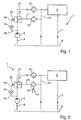
- Oil system 1 an oil reservoir 2, from which an oil pump 3 oil sucks.
- the oil pump 3 is on the suction side via a suction line 4 connected to the reservoir 2.
- the assembly arrangement 6 can, for example be formed by a machine or machine system which is supplied with oil for lubrication.
- the oil system 1 forms then a lubricating oil system.
- the assembly arrangement 6 a single hydraulic unit or a complete hydraulic system, e.g. be a machine. In this case forms the oil system 1 is a hydraulic oil system.
- the oil Downstream of the assembly arrangement 6, the oil is fed via a return line 7 returned to the reservoir 2. Upstream the assembly arrangement 6 is in the feed line 5 an oil filter 8 is arranged, which serves to remove common impurities, in particular suspended particles or the like to filter out the oil. Between the oil filter 8 and the oil pump 3 is a switching valve 9 is arranged, which by means of a electromagnetic actuator 10 at least between two switch positions is switchable. In a first Switch position connects the changeover valve 9 the pressure side the pump 3 with the section leading to the assembly arrangement 6 the supply line 5. In a second switching position connects the switching valve 9 the pressure side of the Pump 3 with a bypass line 11, bypassing the Oil filter 8 and the assembly arrangement 6 in the reservoir 2 returns.
- this bypass line 11 is a dehydration element 12 arranged that with a flow with oil reduces the water content of the oil. Downstream of the dehydration element 12 can the bypass line 11 at a special embodiment with an interrupted Line shown supply line 13 downstream of the oil filter 8 to be connected to the feed line 5. To this In this way, the unit arrangement 6 can also be (dewatered) Oil are supplied when the changeover valve 9 is in its second switching position. Likewise is one mixed transfer of the dewatered oil downstream of the Dehydration element 12 possible, in which the oil partially the assembly arrangement 6 and partly the reservoir 2 is fed; on the representation of corresponding valve means has been waived.
- a sensor 14 with the extracted oil Communicates between the changeover valve 9 and the oil pump 3 a sensor 14 with the extracted oil.
- the sensor 14 monitors the water content in the oil and actuates the via a corresponding line 16 Changeover valve 9 as soon as the water content in the oil is critical Value reached.
- the sensor 14 is present designed as a turbidity sensor, the mode of operation continues is described below, in particular with respect to FIG. 6.
- the arrangement of the sensor 14 selected here is upstream of the changeover valve 9 is preferred, it may well make sense be the sensor 14 at another point in the oil system 1, e.g. in reservoir 2 or in the return line 7th
- FIGS. 1 and 2 differ by the type of dehydration element 12.
- the dehydration element 12 formed by an absorber in the form of a filter element can be trained.
- the absorber saves the water extracted from the oil.
- One designed as an absorber Dehydration element 12 contains, for example a gel-filled filter element that has a chemical bond with water extracted from the oil.
- the dehumidifying element 12 in the embodiment 2 formed by a coalescer, which in the Flow with water-containing oil separates the water from the oil and allows water to drain from the oil flow.
- the water extracted in this way can be separated Containers 17 are collected. Because both absorber and Commonly known coalescers can be a more in-depth Description of these components is omitted.
- Oil system 1 works as follows:
- the oil contains an allowable amount of impurities, especially water, so that the turbidity sensor 14 or a control device coupled to it Switchover valve 9 switches to its first switching position. Accordingly, the oil flows through the oil filter 8 to the assembly arrangement 6. Since the bypass line 11 in normal operation is not flowed through, there can be no flow through form the dehydration element 12, so that this in Normal operation is protected and ready for emergency operation is.
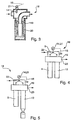
- Filter 18 has a housing 19 in which a filter element 20 is arranged.
- the filter element 20 can be an oil filter element be so that the filter 18 forms an oil filter, this, for example, the oil filter 8 of FIGS. 1 and 2 Oil system 1 shown corresponds.
- the filter element 20 be an absorber filter element.
- the changeover valve 9 in the housing 19 of the filter 18th be integrated.
- both the oil filter are in the housing 19 8 and the water extraction element 12, accordingly separated inside the housing 19 Flow paths are formed.
- the switching valve 9 switches an input 22 of the filter 18 in normal operation on the oil filter 8 and in emergency operation on the water extraction element 12.
- the filter housing 19 has only one outlet 23 on; an embodiment with two outputs can also be used be provided.
- FIGS. 4 and 5 differ in again essentially due to the type of dehydration element 12, which is preferred in the variant according to FIG. 4 by an absorber and preferably in the variant according to FIG. 5 is formed by a coalescer.
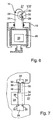
- turbidity sensor according to the invention 14 a pin-like sensor section 24 and a Control unit 25, which includes electronics 26 and a control unit, include an evaluation unit and the like can.
- the sensor 14 is mounted so that its sensor section 24 in a flowed through by the oil to be monitored Room 27 protrudes, the control unit 25 outside the Room 27 can be arranged. Penetrates accordingly the sensor section 24, for example the housing 19.
- the sensor 14 has a measuring section in its sensor section 24 28, which is open to room 27 and accordingly penetrated by the oil in room 27 or can be flowed through. Furthermore, there is at least one transmitter 29 provided the light, preferably infrared light in the measuring section 28 and thus radiates into the oil therein. The infrared light traverses the measuring section 28 and generally encounters at least one receiver 30 which senses the incoming light intensity or light intensity. The transmission of the infrared light through the measuring section 28 or by the oil therein is in Fig. 6 by a Arrow 31 shown symbolically.
- Transmitter 29 and receiver 30 are connected to control unit 25 connected in which e.g. one evaluation unit one with the Transmission 31 can generate correlated signal value. Therefore the light beam certain light wavelengths in particular Infrared range are preferred, the light beam can be clear Run through oil almost unhindered during the Light beam with increasing water content, i.e. with increasing Turbidity is increasingly hindered. In other words, ever the greater the water content in the oil, the less light can come from Receiver 30 are sensed. Reducing infrared light transmission with increasing water content results on the one hand due to an absorption effect of the water Infrared light. On the other hand, the water enters the oil system regularly as an emulsion in the oil, so that diffraction, Refraction and scattering effects hinder transmission can.
- Fig. 7 is a designated in Fig. 6 with VII detail of Sensor 14 reproduced on an enlarged scale, however in a preferred embodiment.
- the sensor 14 here has a transmitter unit 29 which has two transmitters 32 having. These transmission points 32 can, for example, by two diaphragms can be formed by a common transmitter be charged. Likewise, one for each sending point 32 separate transmitter may be provided. Furthermore, the Sensor 14 a receiver unit 30, the two receiving points 33 has. Here, too, the receiver points 33 can Apertures are formed, to which a common receiver is assigned is. Alternatively, the recipient sites 33 can each a separate recipient can be assigned.
- the measuring section 28 is formed, which communicates with the space 27, so that the measuring section 28 with the monitored Oil can be applied.
- the two signal paths 34, 35 differ from each other in terms of their extension length 36 or 37 with which they are within the measuring section 28, i.e. through the oil to be monitored. in the In the present case, both signal paths 34 and 35 run at least partly within the measuring section 28. Likewise an embodiment possible in which the one signal path 34 runs completely outside the measuring section 28.
- the different Extension lengths 36 and 37 are here achieved by a step 38 which protrudes into the measuring section 28. In this stage 38 there is a translucent line 39 trained, e.g. in the form of a hole or Light guide.
- the degree of contamination from a comparison of those at the receiving points 33 sensed received signals can be determined. hereby the measurement is independent of current fluctuations or Voltage fluctuations and signs of aging in the Transmitter unit 29 or in the receiver unit 30, since this in both signal paths 34, 35 in the same way impact. In addition, this arrangement can also do this used, the proper functioning of the sensor 14 monitor. Due to the different extension lengths 36 and 37 are the sensible ones in the case of turbidity Receive signals in the two signal paths 34, 35 inevitably different. Take with increasing turbidity the two received signals according to a first functional Relationship to different degrees. If, for example due to a current fluctuation, the transmission power of the transmitter unit 29 decreases, this has the consequence that both received signals then according to a second functional relationship lose weight. This difference can differ from a corresponding one Evaluation device can be recognized.
Landscapes
- Engineering & Computer Science (AREA)
- General Engineering & Computer Science (AREA)
- General Health & Medical Sciences (AREA)
- Chemical & Material Sciences (AREA)
- Analytical Chemistry (AREA)
- Biochemistry (AREA)
- Physics & Mathematics (AREA)
- General Physics & Mathematics (AREA)
- Immunology (AREA)
- Pathology (AREA)
- Life Sciences & Earth Sciences (AREA)
- Health & Medical Sciences (AREA)
- Mechanical Engineering (AREA)
- Investigating Or Analysing Materials By Optical Means (AREA)
- Lubricants (AREA)
Applications Claiming Priority (3)
| Application Number | Priority Date | Filing Date | Title |
|---|---|---|---|
| DE19957592A DE19957592A1 (de) | 1999-11-30 | 1999-11-30 | Ölsystem, insbesondere Hydrauliksystem oder Schmierölsystem |
| DE19957592 | 1999-11-30 | ||
| PCT/DE2000/004234 WO2001040701A2 (de) | 1999-11-30 | 2000-11-29 | Ölsystem, insbesondere hydrauliksystem oder schmierölsystem |
Publications (2)
| Publication Number | Publication Date |
|---|---|
| EP1234138A2 EP1234138A2 (de) | 2002-08-28 |
| EP1234138B1 true EP1234138B1 (de) | 2003-11-05 |
Family
ID=7930853
Family Applications (1)
| Application Number | Title | Priority Date | Filing Date |
|---|---|---|---|
| EP00989810A Expired - Lifetime EP1234138B1 (de) | 1999-11-30 | 2000-11-29 | Ölsystem, insbesondere hydrauliksystem oder schmierölsystem |
Country Status (5)
| Country | Link |
|---|---|
| US (1) | US6746610B2 (enExample) |
| EP (1) | EP1234138B1 (enExample) |
| JP (1) | JP2003515707A (enExample) |
| DE (2) | DE19957592A1 (enExample) |
| WO (1) | WO2001040701A2 (enExample) |
Families Citing this family (26)
| Publication number | Priority date | Publication date | Assignee | Title |
|---|---|---|---|---|
| US7218397B1 (en) * | 1999-09-17 | 2007-05-15 | Pall Corporation | Methods and systems for counting particles and sensing water |
| DE10119932A1 (de) * | 2001-04-23 | 2002-10-31 | Mahle Filtersysteme Gmbh | Transmissionssensor |
| DE10208600A1 (de) * | 2002-02-27 | 2003-09-04 | Mann & Hummel Filter | Ölqualitätsmeßeinrichtung |
| DE10310380B3 (de) * | 2003-03-07 | 2004-10-14 | Carl Freudenberg Kg | Vorrichtung und Verfahren zur Messung des Ölverlustes oder der Leckrate an Dichtungen |
| DE10343457C5 (de) * | 2003-09-19 | 2012-01-12 | Hydac Filtertechnik Gmbh | Vorrichtung zur Partikelmessung |
| DE102004007749A1 (de) * | 2004-02-18 | 2005-09-08 | Zf Friedrichshafen Ag | Vorrichtung und Verfahren zur Erkennung von Wasserdampf in Öl in einem Gehäuse, vorzugsweise Getriebegehäuse |
| CN101115992B (zh) * | 2004-12-08 | 2014-07-02 | 格特·霍斯特迈尔 | 用来分析内燃机中的机油的检测介质 |
| DE102004061412B3 (de) * | 2004-12-21 | 2006-02-02 | Daimlerchrysler Ag | Verfahren und Vorrichtung zur Ermittlung eines Schmiermittelstroms |
| US7550075B2 (en) * | 2005-03-23 | 2009-06-23 | Tokyo Electron Ltd. | Removal of contaminants from a fluid |
| US20060278584A1 (en) * | 2005-05-23 | 2006-12-14 | Bowden Robert W | Oil cleaning system and method |
| DE202007019631U1 (de) | 2007-06-29 | 2014-08-26 | Martechnic Gmbh | Einrichtung zur Bestimmung des Wassergehalts in Mineralölen und ähnlichen Flüssigkeiten |
| DE102007037525A1 (de) * | 2007-08-09 | 2009-02-12 | Joma-Polytec Kunststofftechnik Gmbh | Ölfiltersystem und Verfahren zum Betreiben eines Ölfiltersystems |
| DE102008003179A1 (de) * | 2008-01-04 | 2009-07-16 | Airbus Deutschland Gmbh | Verfahren und Vorrichtung zum Entwässern einer Hydraulikflüssigkeit |
| GB201003614D0 (en) * | 2010-03-04 | 2010-04-21 | Airbus Operations Ltd | Water drain tool |
| US20120160020A1 (en) * | 2010-12-23 | 2012-06-28 | Roger Burger | Apparatus and method for moisture detection in a refridgerant/oil mixture |
| ES2657592T3 (es) * | 2011-03-03 | 2018-03-06 | Ntn Corporation | Sistema de supervisión de estado para dispositivo rodante y procedimiento de ajuste de umbral para el sistema de supervisión de estado |
| US8596417B2 (en) | 2011-07-05 | 2013-12-03 | Honeywell International Inc. | Lubrication systems with nozzle blockage detection systems |
| SE1550049A1 (sv) * | 2015-01-21 | 2016-07-22 | Osakeyhtiö Skf Ab | System, method & computer program product |
| CN105443966B (zh) * | 2015-12-29 | 2019-04-02 | 杭州杰牌传动科技有限公司 | 一种基于静电吸附的减速器润滑油检测装置及其使用方法 |
| US10711668B2 (en) * | 2016-01-25 | 2020-07-14 | Ford Global Technologies, Llc | Lubrication system monitoring assembly and method |
| WO2017188314A1 (ja) * | 2016-04-28 | 2017-11-02 | 日本精工株式会社 | 潤滑剤劣化検出装置、潤滑剤劣化状態評価方法 |
| DE102018004096A1 (de) * | 2018-05-19 | 2019-11-21 | Hydac Process Technology Gmbh | Phasentrennvorrichtung |
| DE102020114316A1 (de) | 2020-05-28 | 2021-12-02 | Voith Patent Gmbh | Anlage und Verfahren zur Versorgung einer Schmierstelle mit Schmieröl |
| CN112460460B (zh) * | 2020-11-05 | 2021-06-04 | 崇左南方水泥有限公司 | 水泥磨磨头智能调控系统 |
| US20220288523A1 (en) * | 2021-03-01 | 2022-09-15 | Phuc Labs, Inc. | System and method for the identification and separation of compounds carried in a fluid stream |
| DE102024103396A1 (de) * | 2024-02-07 | 2025-08-07 | Mann+Hummel Gmbh | Fluidkreislauf und Verfahren zum Steuern und/oder Regeln eines Fluidkreislaufs |
Family Cites Families (26)
| Publication number | Priority date | Publication date | Assignee | Title |
|---|---|---|---|---|
| US3003353A (en) * | 1958-09-29 | 1961-10-10 | Yosemite Chemical Co | Method and apparatus for testing oil for moisture content |
| DE6911670U (de) | 1969-03-22 | 1974-12-12 | Baier Erdmann Dipl-Ing | Gebaeude aus fertigteilen mit einem grundrissraster |
| US3966603A (en) * | 1975-11-25 | 1976-06-29 | Grant Michael G | Oil-in-water monitor |
| US4499376A (en) * | 1981-03-23 | 1985-02-12 | Paul T. Frost | Hydraulic oil counting device and water separator |
| JPS6051508A (ja) * | 1983-08-31 | 1985-03-23 | Toyota Motor Corp | 循環油中水分の除去装置 |
| US4649281A (en) * | 1985-07-02 | 1987-03-10 | The United States Of America As Represented By The Secretary Of The Navy | Oil content monitor/control system |
| US4649711A (en) * | 1985-09-03 | 1987-03-17 | Carrier Corporation | Apparatus and method for infrared optical electronic qualitative analysis of a fluid independent of the temperature thereof |
| GB2194333B (en) | 1986-07-01 | 1990-08-29 | Electricity Council | Detection method and device |
| DE3843498C1 (enExample) * | 1988-12-23 | 1990-06-13 | Heidelberger Druckmaschinen Ag, 6900 Heidelberg, De | |
| US5049742A (en) * | 1989-11-16 | 1991-09-17 | Kyodo Oil Technical Research Co., Ltd. | Apparatus for detecting deterioration of engine oil |
| IT1237973B (it) * | 1990-02-09 | 1993-06-19 | Filtro olio di lubrificazione di motori a combustione interna per automezzi | |
| JPH03238003A (ja) * | 1990-02-13 | 1991-10-23 | Tomoe Kogyo Kk | 舶用燃料油中の含有水分除去方法および装置 |
| JPH0752479Y2 (ja) * | 1990-03-19 | 1995-11-29 | 石川島播磨重工業株式会社 | 製紙機械のロール軸受潤滑装置 |
| US5107118A (en) * | 1990-10-01 | 1992-04-21 | Uop | Measurement of water levels in liquid hydrocarbon media |
| JPH0824792B2 (ja) * | 1991-06-05 | 1996-03-13 | 富士車輌株式会社 | ドライクリーニング機 |
| DE4233220A1 (de) | 1992-10-02 | 1994-04-07 | Conducta Endress & Hauser | Verfahren und Vorrichtung zur Trübungsmessung bei wässrigen Medien |
| US5599460A (en) * | 1993-08-13 | 1997-02-04 | Van Schoiack; Michael | Water/glycol sensor for use in oil systems |
| US5537336A (en) * | 1994-03-30 | 1996-07-16 | On-Site Analysis, Inc. | On-site oil analyzer |
| JPH08247942A (ja) * | 1995-03-10 | 1996-09-27 | Horiba Ltd | 赤外線ガス分析計 |
| JPH0996398A (ja) * | 1995-09-29 | 1997-04-08 | Shimadzu Corp | 潤滑油管理システム |
| JPH09318526A (ja) * | 1996-03-29 | 1997-12-12 | Japan Energy Corp | 油中水分検知器および油中水分量の測定方法 |
| DE19650397A1 (de) * | 1996-12-05 | 1998-06-10 | Joerg Prof Dr Ing Hoffmann | Ermittlung des Verschleißgrades von Öl unter Nutzung der Absorption von Infrarotstrahlung im Bereich um 10,3 um Wellenlänge |
| US5968371A (en) * | 1998-01-26 | 1999-10-19 | Nelson Industries, Inc. | Lubricant circulation diagnostic and modeling system |
| US6076049A (en) | 1998-02-26 | 2000-06-13 | Premier Instruments, Inc. | Narrow band infrared water cut meter |
| US6014894A (en) | 1998-05-12 | 2000-01-18 | Herron; Bobby Joe | Motor sensor system |
| US6478953B2 (en) * | 2000-11-30 | 2002-11-12 | Porous Media Corporation | Oil filter and dehydrator |
-
1999
- 1999-11-30 DE DE19957592A patent/DE19957592A1/de not_active Withdrawn
-
2000
- 2000-11-29 JP JP2001542132A patent/JP2003515707A/ja active Pending
- 2000-11-29 DE DE50004375T patent/DE50004375D1/de not_active Expired - Lifetime
- 2000-11-29 EP EP00989810A patent/EP1234138B1/de not_active Expired - Lifetime
- 2000-11-29 WO PCT/DE2000/004234 patent/WO2001040701A2/de not_active Ceased
- 2000-11-29 US US10/148,122 patent/US6746610B2/en not_active Expired - Lifetime
Also Published As
| Publication number | Publication date |
|---|---|
| WO2001040701A3 (de) | 2002-01-17 |
| JP2003515707A (ja) | 2003-05-07 |
| EP1234138A2 (de) | 2002-08-28 |
| DE50004375D1 (de) | 2003-12-11 |
| US6746610B2 (en) | 2004-06-08 |
| US20030116509A1 (en) | 2003-06-26 |
| DE19957592A1 (de) | 2001-06-07 |
| WO2001040701A2 (de) | 2001-06-07 |
Similar Documents
| Publication | Publication Date | Title |
|---|---|---|
| EP1234138B1 (de) | Ölsystem, insbesondere hydrauliksystem oder schmierölsystem | |
| EP1393046B1 (de) | Transmissionssensor | |
| DE4427892C2 (de) | Überwachung des Verunreinigungsgrades von Flüssigkeiten | |
| DE60102520T2 (de) | Verfahren und Vorrichtung zum Warnen eines Bedieners eines Fahrzeugs | |
| DE102008014905A1 (de) | Kraftstoffverunreinigungs-Lichtsensor | |
| DE102007003023A1 (de) | Optoelektronischer Sensor mit Lichtdurchlässigkeitstests der Schutzscheibe durch Totalreflexion | |
| EP1849672A2 (de) | Kartusche, Druckluftaufbereitungsanlage und Verfahren zum Betrieb einer Druckluftaufbereitungsanlage | |
| EP2864779B1 (de) | Verfahren und vorrichtung zur messung des gasgehalts in einer flüssigkeit sowie verwendung einer solchen vorrichtung | |
| EP2008080A1 (de) | Verfahren und sensorvorrichtung zur bestimmung der partikelzahl in einem ölvolumen | |
| DE102016123900B4 (de) | Vorrichtung zum Erfassen von Korrosion an einer Zahnstange des Lenksystems, Lenksystem | |
| EP2885620B1 (de) | Vorrichtung zum feststellen von partikelverschmutzungen in fluiden | |
| WO2010020433A1 (de) | Verfahren und lichttaster zum nachweis von objekten | |
| DE10356755B4 (de) | Kraftstoffstand-System für ein Automobil | |
| DE19912971C1 (de) | Verfahren zur Erfassung der Lichtleistung einer Sendediode einer optischen Überwachungseinheit sowie geeignete Schaltungsanordnung | |
| DE3030499C2 (de) | Anordnung zur Feststellung von Partikeln in einer Gasströmung | |
| DE10135448B4 (de) | Vorrichtung zur Erfassung von Fluidverunreinigungen | |
| DE2654726B1 (de) | Einrichtung zur UEberwachung einer Gasstroemung auf in dieser vorhandene Partikel | |
| DE102007034606A1 (de) | System zum Erfassen optischer Signale mit einem Regensensor und Verfahren | |
| DE19653269C1 (de) | Rückspülbare Filtereinrichtung | |
| DE29700253U1 (de) | Überwachungseinrichtung | |
| DE102022203424A1 (de) | Flüssigkeitssensoranordnung | |
| EP2255163B1 (de) | Vorrichtung zur leckageerkennung auf einem schiff | |
| DE10040647A1 (de) | Einrichtung und Verfahren zur Überwachung von Fahrzeugreifen | |
| DE2937686A1 (de) | Kombinationsdetektor | |
| DE102006013612A1 (de) | Einrichtung zur Erfassung des Durchflusses oder der Wärme- oder Energiemenge eines in einer Rohrleitung strömenden Mediums, insbesondere Wassers |
Legal Events
| Date | Code | Title | Description |
|---|---|---|---|
| PUAI | Public reference made under article 153(3) epc to a published international application that has entered the european phase |
Free format text: ORIGINAL CODE: 0009012 |
|
| 17P | Request for examination filed |
Effective date: 20020412 |
|
| AK | Designated contracting states |
Kind code of ref document: A2 Designated state(s): AT BE CH CY DE DK ES FI FR GB GR IE IT LI LU MC NL PT SE TR |
|
| AX | Request for extension of the european patent |
Free format text: AL;LT;LV;MK;RO;SI |
|
| RIN1 | Information on inventor provided before grant (corrected) |
Inventor name: WIERLING, REINHARD Inventor name: MANZ, ROLF |
|
| GRAH | Despatch of communication of intention to grant a patent |
Free format text: ORIGINAL CODE: EPIDOS IGRA |
|
| GRAS | Grant fee paid |
Free format text: ORIGINAL CODE: EPIDOSNIGR3 |
|
| GRAA | (expected) grant |
Free format text: ORIGINAL CODE: 0009210 |
|
| AK | Designated contracting states |
Kind code of ref document: B1 Designated state(s): DE FR GB |
|
| REG | Reference to a national code |
Ref country code: GB Ref legal event code: FG4D Free format text: NOT ENGLISH |
|
| REF | Corresponds to: |
Ref document number: 50004375 Country of ref document: DE Date of ref document: 20031211 Kind code of ref document: P |
|
| REG | Reference to a national code |
Ref country code: IE Ref legal event code: FG4D Free format text: GERMAN |
|
| GBT | Gb: translation of ep patent filed (gb section 77(6)(a)/1977) |
Effective date: 20031220 |
|
| LTIE | Lt: invalidation of european patent or patent extension |
Effective date: 20031105 |
|
| REG | Reference to a national code |
Ref country code: IE Ref legal event code: FD4D |
|
| ET | Fr: translation filed | ||
| PLBE | No opposition filed within time limit |
Free format text: ORIGINAL CODE: 0009261 |
|
| STAA | Information on the status of an ep patent application or granted ep patent |
Free format text: STATUS: NO OPPOSITION FILED WITHIN TIME LIMIT |
|
| 26N | No opposition filed |
Effective date: 20040806 |
|
| REG | Reference to a national code |
Ref country code: FR Ref legal event code: PLFP Year of fee payment: 16 |
|
| PGFP | Annual fee paid to national office [announced via postgrant information from national office to epo] |
Ref country code: GB Payment date: 20151130 Year of fee payment: 16 |
|
| PGFP | Annual fee paid to national office [announced via postgrant information from national office to epo] |
Ref country code: FR Payment date: 20151130 Year of fee payment: 16 |
|
| PGFP | Annual fee paid to national office [announced via postgrant information from national office to epo] |
Ref country code: DE Payment date: 20160129 Year of fee payment: 16 |
|
| REG | Reference to a national code |
Ref country code: DE Ref legal event code: R119 Ref document number: 50004375 Country of ref document: DE |
|
| GBPC | Gb: european patent ceased through non-payment of renewal fee |
Effective date: 20161129 |
|
| REG | Reference to a national code |
Ref country code: FR Ref legal event code: ST Effective date: 20170731 |
|
| PG25 | Lapsed in a contracting state [announced via postgrant information from national office to epo] |
Ref country code: FR Free format text: LAPSE BECAUSE OF NON-PAYMENT OF DUE FEES Effective date: 20161130 |
|
| PG25 | Lapsed in a contracting state [announced via postgrant information from national office to epo] |
Ref country code: GB Free format text: LAPSE BECAUSE OF NON-PAYMENT OF DUE FEES Effective date: 20161129 Ref country code: DE Free format text: LAPSE BECAUSE OF NON-PAYMENT OF DUE FEES Effective date: 20170601 |