EP1231198A1 - Hydroformylierung - Google Patents
Hydroformylierung Download PDFInfo
- Publication number
- EP1231198A1 EP1231198A1 EP02003057A EP02003057A EP1231198A1 EP 1231198 A1 EP1231198 A1 EP 1231198A1 EP 02003057 A EP02003057 A EP 02003057A EP 02003057 A EP02003057 A EP 02003057A EP 1231198 A1 EP1231198 A1 EP 1231198A1
- Authority
- EP
- European Patent Office
- Prior art keywords
- reactor
- reaction
- reaction space
- space
- internals
- Prior art date
- Legal status (The legal status is an assumption and is not a legal conclusion. Google has not performed a legal analysis and makes no representation as to the accuracy of the status listed.)
- Granted
Links
Images

Classifications
-
- C—CHEMISTRY; METALLURGY
- C07—ORGANIC CHEMISTRY
- C07C—ACYCLIC OR CARBOCYCLIC COMPOUNDS
- C07C45/00—Preparation of compounds having >C = O groups bound only to carbon or hydrogen atoms; Preparation of chelates of such compounds
- C07C45/49—Preparation of compounds having >C = O groups bound only to carbon or hydrogen atoms; Preparation of chelates of such compounds by reaction with carbon monoxide
- C07C45/50—Preparation of compounds having >C = O groups bound only to carbon or hydrogen atoms; Preparation of chelates of such compounds by reaction with carbon monoxide by oxo-reactions
-
- B—PERFORMING OPERATIONS; TRANSPORTING
- B01—PHYSICAL OR CHEMICAL PROCESSES OR APPARATUS IN GENERAL
- B01J—CHEMICAL OR PHYSICAL PROCESSES, e.g. CATALYSIS OR COLLOID CHEMISTRY; THEIR RELEVANT APPARATUS
- B01J19/00—Chemical, physical or physico-chemical processes in general; Their relevant apparatus
- B01J19/0053—Details of the reactor
- B01J19/006—Baffles
-
- B—PERFORMING OPERATIONS; TRANSPORTING
- B01—PHYSICAL OR CHEMICAL PROCESSES OR APPARATUS IN GENERAL
- B01J—CHEMICAL OR PHYSICAL PROCESSES, e.g. CATALYSIS OR COLLOID CHEMISTRY; THEIR RELEVANT APPARATUS
- B01J19/00—Chemical, physical or physico-chemical processes in general; Their relevant apparatus
- B01J19/24—Stationary reactors without moving elements inside
- B01J19/2415—Tubular reactors
- B01J19/2435—Loop-type reactors
-
- B—PERFORMING OPERATIONS; TRANSPORTING
- B01—PHYSICAL OR CHEMICAL PROCESSES OR APPARATUS IN GENERAL
- B01J—CHEMICAL OR PHYSICAL PROCESSES, e.g. CATALYSIS OR COLLOID CHEMISTRY; THEIR RELEVANT APPARATUS
- B01J19/00—Chemical, physical or physico-chemical processes in general; Their relevant apparatus
- B01J19/24—Stationary reactors without moving elements inside
- B01J19/2455—Stationary reactors without moving elements inside provoking a loop type movement of the reactants
- B01J19/246—Stationary reactors without moving elements inside provoking a loop type movement of the reactants internally, i.e. the mixture circulating inside the vessel such that the upward stream is separated physically from the downward stream(s)
-
- B—PERFORMING OPERATIONS; TRANSPORTING
- B01—PHYSICAL OR CHEMICAL PROCESSES OR APPARATUS IN GENERAL
- B01J—CHEMICAL OR PHYSICAL PROCESSES, e.g. CATALYSIS OR COLLOID CHEMISTRY; THEIR RELEVANT APPARATUS
- B01J2219/00—Chemical, physical or physico-chemical processes in general; Their relevant apparatus
- B01J2219/00002—Chemical plants
- B01J2219/00027—Process aspects
- B01J2219/00033—Continuous processes
-
- B—PERFORMING OPERATIONS; TRANSPORTING
- B01—PHYSICAL OR CHEMICAL PROCESSES OR APPARATUS IN GENERAL
- B01J—CHEMICAL OR PHYSICAL PROCESSES, e.g. CATALYSIS OR COLLOID CHEMISTRY; THEIR RELEVANT APPARATUS
- B01J2219/00—Chemical, physical or physico-chemical processes in general; Their relevant apparatus
- B01J2219/00049—Controlling or regulating processes
- B01J2219/00051—Controlling the temperature
- B01J2219/00074—Controlling the temperature by indirect heating or cooling employing heat exchange fluids
- B01J2219/00076—Controlling the temperature by indirect heating or cooling employing heat exchange fluids with heat exchange elements inside the reactor
- B01J2219/00083—Coils
-
- B—PERFORMING OPERATIONS; TRANSPORTING
- B01—PHYSICAL OR CHEMICAL PROCESSES OR APPARATUS IN GENERAL
- B01J—CHEMICAL OR PHYSICAL PROCESSES, e.g. CATALYSIS OR COLLOID CHEMISTRY; THEIR RELEVANT APPARATUS
- B01J2219/00—Chemical, physical or physico-chemical processes in general; Their relevant apparatus
- B01J2219/00049—Controlling or regulating processes
- B01J2219/00051—Controlling the temperature
- B01J2219/00074—Controlling the temperature by indirect heating or cooling employing heat exchange fluids
- B01J2219/00105—Controlling the temperature by indirect heating or cooling employing heat exchange fluids part or all of the reactants being heated or cooled outside the reactor while recycling
- B01J2219/00108—Controlling the temperature by indirect heating or cooling employing heat exchange fluids part or all of the reactants being heated or cooled outside the reactor while recycling involving reactant vapours
-
- B—PERFORMING OPERATIONS; TRANSPORTING
- B01—PHYSICAL OR CHEMICAL PROCESSES OR APPARATUS IN GENERAL
- B01J—CHEMICAL OR PHYSICAL PROCESSES, e.g. CATALYSIS OR COLLOID CHEMISTRY; THEIR RELEVANT APPARATUS
- B01J2219/00—Chemical, physical or physico-chemical processes in general; Their relevant apparatus
- B01J2219/00049—Controlling or regulating processes
- B01J2219/00051—Controlling the temperature
- B01J2219/00074—Controlling the temperature by indirect heating or cooling employing heat exchange fluids
- B01J2219/00105—Controlling the temperature by indirect heating or cooling employing heat exchange fluids part or all of the reactants being heated or cooled outside the reactor while recycling
- B01J2219/0011—Controlling the temperature by indirect heating or cooling employing heat exchange fluids part or all of the reactants being heated or cooled outside the reactor while recycling involving reactant liquids
-
- B—PERFORMING OPERATIONS; TRANSPORTING
- B01—PHYSICAL OR CHEMICAL PROCESSES OR APPARATUS IN GENERAL
- B01J—CHEMICAL OR PHYSICAL PROCESSES, e.g. CATALYSIS OR COLLOID CHEMISTRY; THEIR RELEVANT APPARATUS
- B01J2219/00—Chemical, physical or physico-chemical processes in general; Their relevant apparatus
- B01J2219/00049—Controlling or regulating processes
- B01J2219/00182—Controlling or regulating processes controlling the level of reactants in the reactor vessel
-
- B—PERFORMING OPERATIONS; TRANSPORTING
- B01—PHYSICAL OR CHEMICAL PROCESSES OR APPARATUS IN GENERAL
- B01J—CHEMICAL OR PHYSICAL PROCESSES, e.g. CATALYSIS OR COLLOID CHEMISTRY; THEIR RELEVANT APPARATUS
- B01J2219/00—Chemical, physical or physico-chemical processes in general; Their relevant apparatus
- B01J2219/00761—Details of the reactor
- B01J2219/00763—Baffles
- B01J2219/00765—Baffles attached to the reactor wall
- B01J2219/00777—Baffles attached to the reactor wall horizontal
Definitions
- the invention relates to a process for the hydroformylation of Olefins with at least 6 carbon atoms and a device to carry out the procedure.
- Hydroformylation or oxo synthesis is an important large-scale one Process and is used for the production of aldehydes Olefins, carbon monoxide and hydrogen. These aldehydes can if necessary in the same operation or subsequently in one separate hydrogenation step with hydrogen to the corresponding Alcohols are hydrogenated.
- the hydroformylation takes place in the presence of catalysts homogeneously dissolved in the reaction medium.
- the carbonyl complexes are generally used as catalysts of metals of subgroup VIII, in particular Co, Rh, Ir, Pd, Pt or Ru used, the unmodified or z. B. with aminoder phosphine-containing ligands can be modified.
- a summary Presentation of large-scale processes can be found in J. Falbe, "New Syntheses with Carbon Monoxide", Springer Verlag 1980, p. 162 ff.
- olefins can be at least 6, e.g. B. with 9 to 20, carbon atoms hydroformylate.
- the chain length is up in the Usually limited to around 700 carbon atoms.
- the invention Process is especially for the hydroformylation of isomeric olefin mixtures suitable by oligomerization of lower olefins, such as propene and butenes, are produced.
- oligomerizates that are used as starting materials for the present methods are suitable include dimer, Trimer and tetramer propene, dimer, trimer and tetramer butene and Mixed oligomerizates of propenes and butenes.
- oligomerizates of butenes are by known oligomerization processes, z. B. after the Octol® process by Hüls and the Dimersol® process from IFP, accessible on an industrial scale.
- Processes can also use linear long chain terminal olefins Double bond, the z. B. according to the SHOP® process or Ziegler process are available, or linear long chain olefins be hydroformylated with an internal double bond.
- Other preferred insert olefins are essentially simple unsaturated polyalkylenes with 30 to 700 carbon atoms, such as especially polybutene or polyisobutene.
- the process according to the invention takes place under homogeneous catalysis instead of. As a rule, this is done with the olefin and the synthesis gas a suitable catalyst or catalyst precursor in the Reactor introduced. Regarding the catalysts used or There are no significant restrictions on catalyst precursors.
- cobalt catalysts preferably cobalt carbonyls or cobalt carbonyl hydrogen or their precursors, such as in particular cobalt (II) salts, for.
- the catalyst is expediently dissolved in the feed olefin or an organic which may be used Solvent introduced. You can do this outside of the reactor an aqueous cobalt (II) salt solution in contact with synthesis gas bring, with a hydroformylation active cobalt catalyst is formed, and the aqueous containing the cobalt catalyst Solution at the same time or subsequently with the assignment olefin and / or bring into contact with the organic solvent, the Cobalt catalyst is extracted into the organic phase.
- II aqueous cobalt
- the catalyst is preferably formed beforehand at temperatures from 50 to 200 ° C, especially 100 to 160 ° C and below Pressure from 100 to 400 bar, in particular 200 to 300 bar. It are suitable devices for gas-liquid reactions, such as Stirring tank with gassing stirrer, bubble columns or trickle bed columns.
- the precarbonylation is advantageously carried out in the presence of activated carbon, zeolites or basic ion exchanges are loaded with cobalt carbonyl, as described in DE-OS 2139630. From the cobalt (II) salts and cobalt catalyst thus obtained containing aqueous solution then becomes the cobalt catalyst in the olefins to be hydroformylated and / or optionally extracted organic solvents extracted.
- the formation of the cobalt catalyst, the extraction of the cobalt catalyst into the organic one Phase and the hydroformylation of the olefins in one step take place by the aqueous cobalt (II) salt solution, the olefins, Synthesis gas and optionally the organic solvent together be introduced into the reactor.
- the raw materials are introduced into the reaction zone in such a way that a good Phase mixing takes place and the largest possible phase exchange area is produced.
- the Dosing devices known to those skilled in the art such as, for. B. with packing filled turbulence tubes or mixing nozzles for multiphase systems be used.
- the reaction is discharged to remove the cobalt catalyst suitably after leaving the reaction zone at medium pressure, as a rule 10 to 30 bar, relaxed and in a so-called decobalization stage directed.
- the reaction discharge in the presence of aqueous, weakly acidic cobalt (II) salt solution with air or oxygen at temperatures of preferably 90 to 130 ° C freed of cobalt carbonyl complexes.
- the decobalization can be carried out in a such as B. Raschig rings, filled pressure vessel performed are generated in the largest possible phase exchange area becomes.
- the organic Product phase separated from the aqueous phase In a subsequent phase separation vessel the organic Product phase separated from the aqueous phase.
- cobalt (II) salts When decobbing the hydroformylation-active cobalt catalyst under Formation of cobalt (II) salts, predominantly cobalt (II) formate, decomposed.
- the aqueous cobalt (II) salt solution is appropriately returned to the reaction zone or catalyst formation stage.
- rhodium catalysts can be produced by nitrogen or phosphorus-containing ligands can be used become.
- the separation of the rhodium catalyst from the hydroformylation product is generally carried out by distillation, the Rhodium catalyst together with high-boiling components as Residue remains.
- Synthesis gas is a commercially available mixture of carbon monoxide and hydrogen.
- the composition of the in the invention Synthesis gas used can vary widely Ranges vary.
- the molar ratio of carbon monoxide to Hydrogen is usually about 10: 1 to 1:10, in particular 2.5: 1 to 1: 2.5.
- a preferred ratio is about 1: 1.5.
- Possible organic solvents to be used inert hydrocarbons such as paraffin fractions, aromatic Hydrocarbons such as benzene, toluene or xylene, or a Aldehyde and / or alcohol, but especially the hydroformylation product of the olefin used. It can also high-boiling by-products of hydroformylation as a solvent be used.
- the use of a solvent can e.g. B. for lowering the viscosity of long-chain olefins be beneficial.
- the temperature during the hydroformylation is generally around 100 to 250 ° C, especially 145 to 200 ° C.
- the implementation will preferably at a pressure in the range from 20 to 400 bar, in particular 200 to 300 bar.
- the possibly preheated feed olefin, synthesis gas and if appropriate, catalyst or precursor are placed in a vertical, highly cylindrical reactor supplied, the at least two reaction spaces having.
- the reaction spaces extend essentially in the longitudinal direction of the reactor and are through Separation of the reactor interior by means of internals, which accordingly are arranged essentially in the longitudinal direction of the reactor, educated. "Essentially in the longitudinal direction of the reactor” means that the reaction spaces are their largest expansion in the direction the longitudinal axis of the reactor and the length of a reaction space more than 50%, preferably more than 60%, of the reactor length.
- the internals each form an enclosed space on all sides Reaction space with a feed for the reaction mixture on one End and a discharge for the reaction mixture on the opposite The End.
- the reaction mixture is thus one first reaction chamber supplied from below, it flows through the same from bottom to top and is over at the top of it suitable recycling means in a second reaction chamber fed lower end.
- the reaction mixture are discharged to the outside, but it exists also the possibility to design the reactor and the process in such a way that the reaction mixture from the top of the second reaction space via return means the lower end of a third Reaction space is supplied, optionally in an analogous manner flows through further reaction spaces and finally from the upper Part of the last reaction space is led outside.
- the internals are preferably closed cylinders on both sides formed, each at the two opposite ends Have feed or discharge openings.
- the internals can be next to each other, preferably evenly distributed over the reactor cross-section, particularly preferred but arranged concentrically to each other and to the reactor jacket his.
- the internals form one only inner cylinder closed on both sides with feed on lower end and discharge at the upper end of the same.
- the reaction mixture is particularly preferred first the space fed between the inner wall of the reactor and internals, at the upper end of the intermediate space via feedback means to a second reaction space fed at its lower end, at its upper end optionally in further reaction spaces from bottom to top and finally discharged to the outside.
- the second reaction space thus serves as a post-reaction zone, d. H. to complete the first Reaction space achieved olefin conversion without undesirable backmixing with the content of the first reaction space.
- This measure can be done regardless of the number of existing reaction spaces can be used.
- unreacted synthesis gas z. B. from the upper region of the space between the reactor inner wall and internals deducted and the same reaction space fed again in its lower area.
- the recycle of synthesis gas increases the turbulence in the first reaction space and ensures an intimate Contact of the gas and liquid phases.
- the compression of the recycled, unreacted synthesis gas can advantageously be done by means of a jet pump, whereby it is particularly cheap, the jet pump with the olefin and fresh to operate supplied synthesis gas comprehensive feed stream.
- the Jet pump can be arranged in the lower region of the reactor, however, it is also possible to place it below the reactor, outside to arrange it.
- Jet pump in addition to the educt flow with partially converted reaction mixture, the Z. B. by means of a circulation pump at the bottom End of the first reaction chamber is sucked out of the reactor operate.
- the suctioned reaction mixture can be particularly preferred before feeding to the jet pump for heat dissipation be passed through a heat exchanger.
- each of which is the reaction mixture from the top of a reaction space to the bottom of a lead next reaction room.
- These return agents are special preferably designed as downpipes or syphones.
- the Downpipes are designed so that the upper edge of the Fluid level, d. H. the liquid-gas phase boundary, in the corresponding Reaction space is kept constant. Should the Liquid level will drop below the top edge of the downpipe due to the building up of gas pressure more and more unreacted Syngas through the downpipe into the next reaction space passed until the liquid level again the upper edge of the Down pipe reached, and vice versa. In this way, level control achieved without complex technical measures.
- the high-cylindrical reactor preferably has a slenderness ratio, d. H. a ratio of length to diameter, 1 / d of about 3: 1 to 30: 1, in particular from about 5: 1 to 10: 1.
- the internals in the reactor are preferably dimensioned in such a way that the ratio of the volume of the first reaction space to that of the second reaction space or two further successive ones Reaction spaces 4: 1 to 1: 4, preferably 1.5: 1 to 1: 1.5, particularly preferably about 1: 1.
- the dimensioning of the internals in the longitudinal direction is in the Configured such that the height of the second reaction space (the other reaction spaces) more than 50%, in particular more than 60%, the height of the reactor, particularly preferably 80 to 95% of the Height of the reactor is.
- An additional cascading of the last reaction space, z. B. the second reaction chamber, by means of horizontal anti-diffusion devices, e.g. B. perforated sheets, preferably are arranged equidistant to each other can be achieved.
- the number of perforated plates can be 1 to 10, particularly preferred 3 to 5. This measure has a positive effect on sales the hydroformylation reaction, so that a further increase in sales can be achieved with a given reaction volume.
- the horizontal perforated plates can advantageously outside of Reactor in the internals forming the other reaction spaces be installed, so that the assembly costs are significantly reduced become. They can both be solved by appropriate Flange connections mounted, or directly with the internals be welded.
- the inside of the reactor according to the invention can have means for have indirect cooling of the reaction spaces. Such means are preferred, especially in the first, of the reaction mixture flowed reaction chamber provided. You can prefer as Coils, through which a cooling medium flows, are formed be, with the coils applied to the internals, z. B. welded, or spaced apart could be.
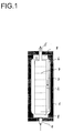
- Fig. 1 shows an example of a reactor 1 according to the invention Longitudinal section with a bottle neck 8 at each end of the reactor, with internals 2, which are concentric, closed on both sides Form inner cylinder with a feed 4 in the Intermediate space 3 between the inner wall of the reactor and the internals 2 and a discharge 5 from that separated by the internals 2 Reaction space, with return means 6 from the upper part of the Space between the inner wall of the reactor and internals 2 to the bottom End of the reaction space separated by the internals 2 as well as with horizontal perforated plates 7, an example being a number is represented by seven perforated plates.
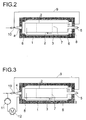
- FIG. 2 shows a further preferred embodiment variant in longitudinal section, which additionally has a return line for gas 9 from the upper area of the space between the reactor interior and Built-in components 2, the return line 9 to one below of the reactor arranged jet pump 10 leads through the liquid educt mixture is operated.
- Fig. 3 shows a further preferred embodiment in longitudinal section represents, the jet pump arranged below the reactor 10 additionally operated with a liquid reaction mixture will that from the lower part of the reactor using a circulating pump 11 withdrawn and fed to the jet pump, and the liquid reaction mixture first via a heat exchanger 12 is cooled.
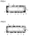
- the embodiment variant shown in longitudinal section in FIG. 4 additionally shows coils 13, which are applied to the internals 2 are and thus the space between the inner wall of the reactor and internals 2 as well as those separated by internals 2 Cool the interior of the reactor.
- FIG. 5 shows coils 13 only in the space between the inner wall of the reactor and internals 2 are arranged and thus predominantly this space cool.
- FIG. 6 shows an embodiment with three reaction spaces, by concentric arrangement of two cylindrical internals 2 are formed within the reactor 1.
- the invention Device exhibits lower investment and operating costs known devices.
- the following mathematical simulation illustrates the invention in more detail.
- the simulation is based on a kinetic model of the hydroformylation of polyisobutene, which was created by mathematically adapting a large number of experimental measurement results.
- a mixture of 80% by weight of an easily convertible, slightly branched polyisobutene A 1 and 20% by weight of a difficult to convert, more branched polyisobutene A 2 was assumed as the feed.
- a 10% excess of synthesis gas (molar ratio CO / H 2 1: 1), a reaction temperature of 130 ° C. and a pressure of 280 bar were used as a basis.
- reaction rates of the conversion of A 1 and A 2 to the respective hydroformylation product are proportional to the molar proportions of A 1 and A 2 , respectively.
- a dependence on the CO or H 2 concentration was neglected. It was assumed that the reaction volume does not change as a result of the reactions.
- the underlying mass flow of olefin feed and catalyst solution (aqueous cobalt (II) formate solution) was 6000 kg / h in each case.
Abstract
Description
- Figur 1
- die schematische Darstellung einer bevorzugten Ausführungsform einer erfindungsgemäßen Vorrichtung im Längsschnitt,
- Figur 2
- eine weitere bevorzugte Ausführungsform einer erfindungsgemäßen Vorrichtung im Längsschnitt mit Gasrückführung über eine Strahlpumpe,
- Figur 3
- eine weitere Ausgestaltung der Vorrichtung aus Figur 2 mit zusätzlicher Rückführung eines Teils des Reaktionsgemisches über die Strahlpumpe,
- Figur 4
- eine weitere bevorzugte Ausgestaltung im Längsschnitt mit auf den Einbauten aufgebrachten Rohrschlangen,
- Figur 5
- eine Ausführungsvariante mit Rohrschlangen, die nicht auf den Einbauten aufgebracht sind,
- Figur 6
- eine Ausführungsvariante mit drei Reaktionsräumen im Längsschnitt sowie im Querschnitt (Figur 6a) und
- Figur 7a
- einen Querschnitt durch einen erfindungsgemäßen Reaktor mit nicht konzentrischen Einbauten.
| Beispiel | Umsatz A1 | Umsatz A2 | Gesamtumsatz A1+A2 |
| I | 78,3 % | 26,5 % | 67,9 % |
| II | 91,3 % | 28,9 % | 78,8 % |
Claims (10)
- Kontinuierliches Verfahren zur Hydroformylierung von Olefinen mit wenigstens 6 Kohlenstoffatomen unter homogener Katalyse, bei dem mana) einen vertikalen hochzylindrischen Reaktor (1) verwendet, dessen Innenraum mittels Einbauten (2) in wenigstens zwei Reaktionsräume unterteilt ist, die sich im Wesentlichen in Reaktorlängsrichtung erstrecken,b) wenigstens ein Olefin zusammen mit Synthesegas am unteren Ende des ersten Reaktionsraums in den Reaktor einführt,c) vom oberen Ende eines Reaktionsraumes ein teilumgesetztes Reaktionsgemisch zum unteren Ende eines nächsten Reaktionsraums führt; undd) am oberen Ende des letzten Reaktionsraums das hydroformylierte Olefin entnimmt.
- Verfahren nach Anspruch 1, bei dem man einen Reaktor (1) verwendet, dessen Innenraum mittels Einbauten (2) so unterteilt ist, dass der zweite und gegebenenfalls weitere Reaktionsräume im Wesentlichen konzentrisch zum Reaktormantel angeordnet sind.
- Verfahren nach Anspruch 1 oder 2, bei dem man nicht umgesetztes Synthesegas vom Gasraum am oberen Ende eines oder mehrerer Reaktionsräume mit Ausnahme des letzten Reaktionsraums entnimmt und erneut in den Reaktor einführt.
- Verfahren nach Anspruch 3, bei dem man das entnommene Synthesegas mittels einer Strahlpumpe (10) in den Reaktor einführt, die mit dem zugeführten Olefin und Synthesegas betrieben wird.
- Verfahren nach Anspruch 4, bei dem die Strahlpumpe (10) zusätzlich mit teilumgesetztem Reaktionsgemisch betrieben wird, das am unteren Ende des ersten Reaktionsraums entnommen wird.
- Vertikaler hochzylindrischer Reaktor (1) zur Durchführung des Verfahrens nach einem der Ansprüche 1 bis 5, mit Einbauten (2), mittels welcher der Innenraum des Reaktors in wenigstens zwei Reaktionsräume unterteilt ist, die sich im Wesentlichen in Reaktorlängsrichtung erstrecken, und Rückführungsmitteln (6) vom oberen Ende eines Reaktionsraums zum unteren Ende eines nächsten Reaktionsraums.
- Reaktor (1) nach Anspruch 6, wobei der zweite und gegebenenfalls weitere Reaktionsräume im Wesentlichen konzentrisch zum Reaktormantel angeordnet sind.
- Reaktor (1) nach Anspruch 6 oder 8 mit einem Schlankheitsgrad 1/d von 3:1 bis 30:1.
- Reaktor (1) nach einem der Ansprüche 6 bis 8, wobei der letzte Reaktionsraum durch horizontale, beabstandet zueinander angeordnete Lochbleche (7) kaskadiert ist.
- Reaktor (1) nach einem der Ansprüche 6 bis 9, wobei die Höhe des zweiten und gegebenenfalls weiterer Reaktionsräume mehr als 50 % der Höhe des Reaktors (1) beträgt.
Applications Claiming Priority (2)
| Application Number | Priority Date | Filing Date | Title |
|---|---|---|---|
| DE10106482A DE10106482A1 (de) | 2001-02-13 | 2001-02-13 | Hydroformylierung |
| DE10106482 | 2001-02-13 |
Publications (2)
| Publication Number | Publication Date |
|---|---|
| EP1231198A1 true EP1231198A1 (de) | 2002-08-14 |
| EP1231198B1 EP1231198B1 (de) | 2005-10-12 |
Family
ID=7673772
Family Applications (1)
| Application Number | Title | Priority Date | Filing Date |
|---|---|---|---|
| EP02003057A Expired - Lifetime EP1231198B1 (de) | 2001-02-13 | 2002-02-12 | Hydroformylierung |
Country Status (4)
| Country | Link |
|---|---|
| US (2) | US7015361B2 (de) |
| EP (1) | EP1231198B1 (de) |
| JP (1) | JP3980366B2 (de) |
| DE (2) | DE10106482A1 (de) |
Cited By (11)
| Publication number | Priority date | Publication date | Assignee | Title |
|---|---|---|---|---|
| EP1338333A1 (de) * | 2002-02-14 | 2003-08-27 | Basf Aktiengesellschaft | Reaktorkaskade aus Haupt- und Nachreaktor |
| US7321068B2 (en) | 2003-12-09 | 2008-01-22 | Basf Aktiengesellschaft | Method for producing tricyclodecandialdehyde |
| US7615645B2 (en) | 2003-10-21 | 2009-11-10 | Basf Aktiengesellschaft | Method for the continuous production of aldehydes |
| WO2013153136A1 (de) | 2012-04-12 | 2013-10-17 | Basf Se | Verfahren zur ergänzung des katalysators bei der kontinuierlichen hydroformylierung |
| US8889917B2 (en) | 2012-04-12 | 2014-11-18 | Basf Se | Method of supplementing the catalyst in continuous hydroformylation |
| WO2018228879A1 (en) | 2017-06-13 | 2018-12-20 | Basf Se | Hydroformylation process for producing 1,6-hexanediol derivatives |
| US10315975B2 (en) | 2015-07-10 | 2019-06-11 | Basf Se | Method for the hydroformylation of 2-substituted butadienes and the production of secondary products thereof, especially ambrox |
| WO2020048986A1 (de) | 2018-09-05 | 2020-03-12 | Basf Se | Reaktor zur durchführung einer reaktion zwischen zwei nicht mischbaren fluiden unterschiedlicher dichte |
| WO2020048998A1 (de) | 2018-09-05 | 2020-03-12 | Basf Se | Verfahren zur durchführung einer gas/flüssig-zweiphasigen hochdruckreaktion |
| US10647651B2 (en) | 2015-10-12 | 2020-05-12 | Basf Se | Hydroformylation process for producing 1,6-disubstituted hexane derivatives |
| WO2021160448A1 (de) | 2020-02-11 | 2021-08-19 | Basf Se | Niederdruckhydroformylierung von diisobuten |
Families Citing this family (6)
| Publication number | Priority date | Publication date | Assignee | Title |
|---|---|---|---|---|
| US7684147B2 (en) * | 2003-12-15 | 2010-03-23 | Univ Bar Ilan | Magnetoelectronic devices based on colossal magnetoresistive thin films |
| DE102004021128A1 (de) * | 2004-04-29 | 2005-11-24 | Oxeno Olefinchemie Gmbh | Vorrichtung und Verfahren für die kontinuierliche Umsetzung einer Flüssigkeit mit einem Gas an einem festen Katalysator |
| JP5468538B2 (ja) * | 2007-05-29 | 2014-04-09 | エルジー・ケム・リミテッド | オレフィンのヒドロホルミル化方法およびそれに用いられる装置 |
| KR101206214B1 (ko) | 2009-01-16 | 2012-12-03 | 주식회사 엘지화학 | 올레핀으로부터의 알코올을 제조하는 시스템 |
| DE102016208843A1 (de) * | 2016-05-23 | 2017-11-23 | Siemens Aktiengesellschaft | Reaktor mit einer Strahlpumpe und Verfahren zum Erhöhen des Drucks eines Reaktanden mit einer Strahlpumpe |
| WO2020048991A1 (de) * | 2018-09-05 | 2020-03-12 | Basf Se | Reaktor zur durchführung einer gas/flüssig-zweiphasigen hochdruckreaktion mit einem schäumenden medium |
Citations (4)
| Publication number | Priority date | Publication date | Assignee | Title |
|---|---|---|---|---|
| DE926846C (de) * | 1952-08-17 | 1955-04-25 | Chemische Verwertungsgesellsch | Verfahren zur Durchfuehrung exothermer Reaktionen, an denen Gase oder Daempfe und Fluessigkeiten beteiligt sind |
| US3929900A (en) * | 1972-12-27 | 1975-12-30 | Ruhrchemie Ag | Continuous process for the production of oxygen containing compounds |
| DE3220858A1 (de) * | 1982-06-03 | 1983-12-08 | Basf Ag, 6700 Ludwigshafen | Verfahren zur hydroformylierung olefinisch ungesaettigter verbindungen |
| EP1057524A2 (de) * | 1999-06-02 | 2000-12-06 | Oxeno Olefinchemie GmbH | Verfahren zur katalytischen Durchführung von Mehrphasenreaktionen, insbesondere Hydroformulierungen |
Family Cites Families (8)
| Publication number | Priority date | Publication date | Assignee | Title |
|---|---|---|---|---|
| FR2038694A5 (de) * | 1969-03-27 | 1971-01-08 | Progil | |
| US3988117A (en) * | 1972-12-27 | 1976-10-26 | Ruhrchemie Aktiengesellschaft | Reactor for the production of oxygen containing compounds |
| JPS5898101A (ja) * | 1981-12-04 | 1983-06-10 | Toyo Eng Corp | 気液接触装置 |
| EP0132224A1 (de) * | 1983-06-24 | 1985-01-23 | Ciba-Geigy Ag | Blasensäulen-Reaktor für Gas-Flüssig-Stoffaustauschreaktionen |
| GB2177616B (en) * | 1985-07-09 | 1988-07-06 | Smidth & Co As F L | Gas suspension reactor |
| US5855741A (en) * | 1990-02-06 | 1999-01-05 | Koch Engineering Company, Inc. | Apparatus for concurrent reaction with distillation |
| US5731473A (en) | 1995-12-06 | 1998-03-24 | Union Carbide Chemicals & Plastics Technology Corporation | Metal-ligand complex catalyzed processes |
| DE19854637A1 (de) * | 1998-11-26 | 2000-05-31 | Basf Ag | Reaktor zur kontinuierlichen Durchführung von Gas-Flüssig-, Flüssig-Flüssig- oder Gas-Flüssig-Fest-Reaktionen |
-
2001
- 2001-02-13 DE DE10106482A patent/DE10106482A1/de not_active Withdrawn
-
2002
- 2002-02-12 JP JP2002034464A patent/JP3980366B2/ja not_active Expired - Fee Related
- 2002-02-12 DE DE50204499T patent/DE50204499D1/de not_active Expired - Lifetime
- 2002-02-12 EP EP02003057A patent/EP1231198B1/de not_active Expired - Lifetime
- 2002-02-13 US US10/073,248 patent/US7015361B2/en not_active Expired - Fee Related
-
2005
- 2005-09-06 US US11/218,532 patent/US7351384B2/en not_active Expired - Fee Related
Patent Citations (4)
| Publication number | Priority date | Publication date | Assignee | Title |
|---|---|---|---|---|
| DE926846C (de) * | 1952-08-17 | 1955-04-25 | Chemische Verwertungsgesellsch | Verfahren zur Durchfuehrung exothermer Reaktionen, an denen Gase oder Daempfe und Fluessigkeiten beteiligt sind |
| US3929900A (en) * | 1972-12-27 | 1975-12-30 | Ruhrchemie Ag | Continuous process for the production of oxygen containing compounds |
| DE3220858A1 (de) * | 1982-06-03 | 1983-12-08 | Basf Ag, 6700 Ludwigshafen | Verfahren zur hydroformylierung olefinisch ungesaettigter verbindungen |
| EP1057524A2 (de) * | 1999-06-02 | 2000-12-06 | Oxeno Olefinchemie GmbH | Verfahren zur katalytischen Durchführung von Mehrphasenreaktionen, insbesondere Hydroformulierungen |
Cited By (13)
| Publication number | Priority date | Publication date | Assignee | Title |
|---|---|---|---|---|
| EP1338333A1 (de) * | 2002-02-14 | 2003-08-27 | Basf Aktiengesellschaft | Reaktorkaskade aus Haupt- und Nachreaktor |
| US7615645B2 (en) | 2003-10-21 | 2009-11-10 | Basf Aktiengesellschaft | Method for the continuous production of aldehydes |
| US7321068B2 (en) | 2003-12-09 | 2008-01-22 | Basf Aktiengesellschaft | Method for producing tricyclodecandialdehyde |
| WO2013153136A1 (de) | 2012-04-12 | 2013-10-17 | Basf Se | Verfahren zur ergänzung des katalysators bei der kontinuierlichen hydroformylierung |
| US8889917B2 (en) | 2012-04-12 | 2014-11-18 | Basf Se | Method of supplementing the catalyst in continuous hydroformylation |
| US10315975B2 (en) | 2015-07-10 | 2019-06-11 | Basf Se | Method for the hydroformylation of 2-substituted butadienes and the production of secondary products thereof, especially ambrox |
| US10647651B2 (en) | 2015-10-12 | 2020-05-12 | Basf Se | Hydroformylation process for producing 1,6-disubstituted hexane derivatives |
| WO2018228879A1 (en) | 2017-06-13 | 2018-12-20 | Basf Se | Hydroformylation process for producing 1,6-hexanediol derivatives |
| US10941092B2 (en) | 2017-06-13 | 2021-03-09 | Basf Se | Hydroformylation process for producing 1,6-hexanediol derivatives |
| WO2020048986A1 (de) | 2018-09-05 | 2020-03-12 | Basf Se | Reaktor zur durchführung einer reaktion zwischen zwei nicht mischbaren fluiden unterschiedlicher dichte |
| WO2020048998A1 (de) | 2018-09-05 | 2020-03-12 | Basf Se | Verfahren zur durchführung einer gas/flüssig-zweiphasigen hochdruckreaktion |
| US11766653B2 (en) | 2018-09-05 | 2023-09-26 | Basf Se | Method for carrying out a gas/fluid two-phase high-pressure reaction |
| WO2021160448A1 (de) | 2020-02-11 | 2021-08-19 | Basf Se | Niederdruckhydroformylierung von diisobuten |
Also Published As
| Publication number | Publication date |
|---|---|
| US7351384B2 (en) | 2008-04-01 |
| US7015361B2 (en) | 2006-03-21 |
| JP3980366B2 (ja) | 2007-09-26 |
| US20020159930A1 (en) | 2002-10-31 |
| JP2002249453A (ja) | 2002-09-06 |
| US20060004231A1 (en) | 2006-01-05 |
| DE50204499D1 (de) | 2006-02-23 |
| EP1231198B1 (de) | 2005-10-12 |
| DE10106482A1 (de) | 2002-08-14 |
Similar Documents
| Publication | Publication Date | Title |
|---|---|---|
| EP1669337B1 (de) | Verfahren zur Herstellung von Alkoholen aus Olefinen durch Hydroformylierung und Hydrierung | |
| EP1231198B1 (de) | Hydroformylierung | |
| EP1204624B1 (de) | Kontinuierliches verfahren zur hydroformylierung von olefinen mit 6 bis 20 kohlenstoffatomen | |
| EP1057524B1 (de) | Verfahren zur katalytischen Durchführung von Hydroformylierungen | |
| EP1674441B1 (de) | Verfahren zur Hydroformylierung von Olefinen | |
| EP1114017B1 (de) | Verfahren zur herstellung von aldehyden und/oder alkoholen oder aminen | |
| EP1106594B1 (de) | Verfahren zur Hydroformylierung von Olefinen | |
| EP1106596B1 (de) | Verfahren zur katalytischen Durchführung von Aldolkonensationen mittels Mehrphasenreaktion | |
| EP1279658B1 (de) | Verfahren zur Hydroformylierung von höheren Olefinen mit Kobaltverbindungen als Katalysator | |
| EP2188236B1 (de) | Einstufiges kontinuierliches verfahren zur hydroformylierung von höheren olefinen oder olefingemischen | |
| EP1485341A2 (de) | Verfahren zur hydroformylierung von olefinen | |
| EP3394022B1 (de) | Zylindrischer reaktor und dessen verwendung zur kontinuierlichen hydroformylierung | |
| EP3492447B1 (de) | Verfahren zur gewinnung von alkoholen aus aldehyden | |
| EP3492446B1 (de) | Verfahren zur gewinnung von alkoholen aus aldehyden | |
| EP2220017A1 (de) | Mehrstufiges kontinuierliches verfahren zur hydroformylierung von höheren olefinen oder olefingemischen | |
| DE102009027978A1 (de) | Verfahren zur Herstellung von Decancarbonsäuren | |
| DE102008007080A1 (de) | Verfahren zur Herstellung von C9-Alkohol aus C8-Olefinen | |
| DE102009016651B4 (de) | Verfahren zur Herstellung von Aldehyden | |
| EP3301084B1 (de) | Kontinuierliches herstellungsverfahren für 2-methylenalkanale | |
| DE10227995A1 (de) | Verfahren zur Hydroformylierung von Olefinen | |
| DE19643154A1 (de) | Verfahren zur Herstellung von Oxidationsprodukten des Cyclohexans im Gegenstrom | |
| DE2653445C2 (de) | Verfahren zur Hydrierung von 4-Acetoxycrotonaldehyd enthaltendem 1,4-Diacetoxybuten-2 | |
| DE10241266A1 (de) | Verfahren zur Hydroformylierung von Olefinen | |
| DE2747302C2 (de) | Verfahren zur kontinuierlichen Herstellung sauerstoffhaltiger Verbindungen | |
| DE975064C (de) | Verfahren zur Herstellung von Alkoholen |
Legal Events
| Date | Code | Title | Description |
|---|---|---|---|
| PUAI | Public reference made under article 153(3) epc to a published international application that has entered the european phase |
Free format text: ORIGINAL CODE: 0009012 |
|
| AK | Designated contracting states |
Kind code of ref document: A1 Designated state(s): AT BE CH CY DE DK ES FI FR GB GR IE IT LI LU MC NL PT SE TR |
|
| AX | Request for extension of the european patent |
Free format text: AL;LT;LV;MK;RO;SI |
|
| 17P | Request for examination filed |
Effective date: 20030213 |
|
| AKX | Designation fees paid |
Designated state(s): BE DE NL |
|
| 17Q | First examination report despatched |
Effective date: 20031014 |
|
| GRAP | Despatch of communication of intention to grant a patent |
Free format text: ORIGINAL CODE: EPIDOSNIGR1 |
|
| GRAS | Grant fee paid |
Free format text: ORIGINAL CODE: EPIDOSNIGR3 |
|
| GRAA | (expected) grant |
Free format text: ORIGINAL CODE: 0009210 |
|
| AK | Designated contracting states |
Kind code of ref document: B1 Designated state(s): BE DE NL |
|
| REF | Corresponds to: |
Ref document number: 50204499 Country of ref document: DE Date of ref document: 20060223 Kind code of ref document: P |
|
| PLBE | No opposition filed within time limit |
Free format text: ORIGINAL CODE: 0009261 |
|
| STAA | Information on the status of an ep patent application or granted ep patent |
Free format text: STATUS: NO OPPOSITION FILED WITHIN TIME LIMIT |
|
| 26N | No opposition filed |
Effective date: 20060713 |
|
| PGFP | Annual fee paid to national office [announced via postgrant information from national office to epo] |
Ref country code: NL Payment date: 20160225 Year of fee payment: 15 |
|
| PGFP | Annual fee paid to national office [announced via postgrant information from national office to epo] |
Ref country code: BE Payment date: 20160225 Year of fee payment: 15 |
|
| PG25 | Lapsed in a contracting state [announced via postgrant information from national office to epo] |
Ref country code: BE Free format text: LAPSE BECAUSE OF NON-PAYMENT OF DUE FEES Effective date: 20170228 |
|
| REG | Reference to a national code |
Ref country code: NL Ref legal event code: MM Effective date: 20170301 |
|
| PG25 | Lapsed in a contracting state [announced via postgrant information from national office to epo] |
Ref country code: NL Free format text: LAPSE BECAUSE OF NON-PAYMENT OF DUE FEES Effective date: 20170301 |
|
| REG | Reference to a national code |
Ref country code: BE Ref legal event code: MM Effective date: 20170228 |
|
| PGFP | Annual fee paid to national office [announced via postgrant information from national office to epo] |
Ref country code: DE Payment date: 20190426 Year of fee payment: 18 |
|
| REG | Reference to a national code |
Ref country code: DE Ref legal event code: R119 Ref document number: 50204499 Country of ref document: DE |
|
| PG25 | Lapsed in a contracting state [announced via postgrant information from national office to epo] |
Ref country code: DE Free format text: LAPSE BECAUSE OF NON-PAYMENT OF DUE FEES Effective date: 20200901 |