EP1231198A1 - Hydroformylation - Google Patents
Hydroformylation Download PDFInfo
- Publication number
- EP1231198A1 EP1231198A1 EP02003057A EP02003057A EP1231198A1 EP 1231198 A1 EP1231198 A1 EP 1231198A1 EP 02003057 A EP02003057 A EP 02003057A EP 02003057 A EP02003057 A EP 02003057A EP 1231198 A1 EP1231198 A1 EP 1231198A1
- Authority
- EP
- European Patent Office
- Prior art keywords
- reactor
- reaction
- reaction space
- space
- internals
- Prior art date
- Legal status (The legal status is an assumption and is not a legal conclusion. Google has not performed a legal analysis and makes no representation as to the accuracy of the status listed.)
- Granted
Links
Images

Classifications
-
- C—CHEMISTRY; METALLURGY
- C07—ORGANIC CHEMISTRY
- C07C—ACYCLIC OR CARBOCYCLIC COMPOUNDS
- C07C45/00—Preparation of compounds having >C = O groups bound only to carbon or hydrogen atoms; Preparation of chelates of such compounds
- C07C45/49—Preparation of compounds having >C = O groups bound only to carbon or hydrogen atoms; Preparation of chelates of such compounds by reaction with carbon monoxide
- C07C45/50—Preparation of compounds having >C = O groups bound only to carbon or hydrogen atoms; Preparation of chelates of such compounds by reaction with carbon monoxide by oxo-reactions
-
- B—PERFORMING OPERATIONS; TRANSPORTING
- B01—PHYSICAL OR CHEMICAL PROCESSES OR APPARATUS IN GENERAL
- B01J—CHEMICAL OR PHYSICAL PROCESSES, e.g. CATALYSIS OR COLLOID CHEMISTRY; THEIR RELEVANT APPARATUS
- B01J19/00—Chemical, physical or physico-chemical processes in general; Their relevant apparatus
- B01J19/0053—Details of the reactor
- B01J19/006—Baffles
-
- B—PERFORMING OPERATIONS; TRANSPORTING
- B01—PHYSICAL OR CHEMICAL PROCESSES OR APPARATUS IN GENERAL
- B01J—CHEMICAL OR PHYSICAL PROCESSES, e.g. CATALYSIS OR COLLOID CHEMISTRY; THEIR RELEVANT APPARATUS
- B01J19/00—Chemical, physical or physico-chemical processes in general; Their relevant apparatus
- B01J19/24—Stationary reactors without moving elements inside
- B01J19/2415—Tubular reactors
- B01J19/2435—Loop-type reactors
-
- B—PERFORMING OPERATIONS; TRANSPORTING
- B01—PHYSICAL OR CHEMICAL PROCESSES OR APPARATUS IN GENERAL
- B01J—CHEMICAL OR PHYSICAL PROCESSES, e.g. CATALYSIS OR COLLOID CHEMISTRY; THEIR RELEVANT APPARATUS
- B01J19/00—Chemical, physical or physico-chemical processes in general; Their relevant apparatus
- B01J19/24—Stationary reactors without moving elements inside
- B01J19/2455—Stationary reactors without moving elements inside provoking a loop type movement of the reactants
- B01J19/246—Stationary reactors without moving elements inside provoking a loop type movement of the reactants internally, i.e. the mixture circulating inside the vessel such that the upward stream is separated physically from the downward stream(s)
-
- B—PERFORMING OPERATIONS; TRANSPORTING
- B01—PHYSICAL OR CHEMICAL PROCESSES OR APPARATUS IN GENERAL
- B01J—CHEMICAL OR PHYSICAL PROCESSES, e.g. CATALYSIS OR COLLOID CHEMISTRY; THEIR RELEVANT APPARATUS
- B01J2219/00—Chemical, physical or physico-chemical processes in general; Their relevant apparatus
- B01J2219/00002—Chemical plants
- B01J2219/00027—Process aspects
- B01J2219/00033—Continuous processes
-
- B—PERFORMING OPERATIONS; TRANSPORTING
- B01—PHYSICAL OR CHEMICAL PROCESSES OR APPARATUS IN GENERAL
- B01J—CHEMICAL OR PHYSICAL PROCESSES, e.g. CATALYSIS OR COLLOID CHEMISTRY; THEIR RELEVANT APPARATUS
- B01J2219/00—Chemical, physical or physico-chemical processes in general; Their relevant apparatus
- B01J2219/00049—Controlling or regulating processes
- B01J2219/00051—Controlling the temperature
- B01J2219/00074—Controlling the temperature by indirect heating or cooling employing heat exchange fluids
- B01J2219/00076—Controlling the temperature by indirect heating or cooling employing heat exchange fluids with heat exchange elements inside the reactor
- B01J2219/00083—Coils
-
- B—PERFORMING OPERATIONS; TRANSPORTING
- B01—PHYSICAL OR CHEMICAL PROCESSES OR APPARATUS IN GENERAL
- B01J—CHEMICAL OR PHYSICAL PROCESSES, e.g. CATALYSIS OR COLLOID CHEMISTRY; THEIR RELEVANT APPARATUS
- B01J2219/00—Chemical, physical or physico-chemical processes in general; Their relevant apparatus
- B01J2219/00049—Controlling or regulating processes
- B01J2219/00051—Controlling the temperature
- B01J2219/00074—Controlling the temperature by indirect heating or cooling employing heat exchange fluids
- B01J2219/00105—Controlling the temperature by indirect heating or cooling employing heat exchange fluids part or all of the reactants being heated or cooled outside the reactor while recycling
- B01J2219/00108—Controlling the temperature by indirect heating or cooling employing heat exchange fluids part or all of the reactants being heated or cooled outside the reactor while recycling involving reactant vapours
-
- B—PERFORMING OPERATIONS; TRANSPORTING
- B01—PHYSICAL OR CHEMICAL PROCESSES OR APPARATUS IN GENERAL
- B01J—CHEMICAL OR PHYSICAL PROCESSES, e.g. CATALYSIS OR COLLOID CHEMISTRY; THEIR RELEVANT APPARATUS
- B01J2219/00—Chemical, physical or physico-chemical processes in general; Their relevant apparatus
- B01J2219/00049—Controlling or regulating processes
- B01J2219/00051—Controlling the temperature
- B01J2219/00074—Controlling the temperature by indirect heating or cooling employing heat exchange fluids
- B01J2219/00105—Controlling the temperature by indirect heating or cooling employing heat exchange fluids part or all of the reactants being heated or cooled outside the reactor while recycling
- B01J2219/0011—Controlling the temperature by indirect heating or cooling employing heat exchange fluids part or all of the reactants being heated or cooled outside the reactor while recycling involving reactant liquids
-
- B—PERFORMING OPERATIONS; TRANSPORTING
- B01—PHYSICAL OR CHEMICAL PROCESSES OR APPARATUS IN GENERAL
- B01J—CHEMICAL OR PHYSICAL PROCESSES, e.g. CATALYSIS OR COLLOID CHEMISTRY; THEIR RELEVANT APPARATUS
- B01J2219/00—Chemical, physical or physico-chemical processes in general; Their relevant apparatus
- B01J2219/00049—Controlling or regulating processes
- B01J2219/00182—Controlling or regulating processes controlling the level of reactants in the reactor vessel
-
- B—PERFORMING OPERATIONS; TRANSPORTING
- B01—PHYSICAL OR CHEMICAL PROCESSES OR APPARATUS IN GENERAL
- B01J—CHEMICAL OR PHYSICAL PROCESSES, e.g. CATALYSIS OR COLLOID CHEMISTRY; THEIR RELEVANT APPARATUS
- B01J2219/00—Chemical, physical or physico-chemical processes in general; Their relevant apparatus
- B01J2219/00761—Details of the reactor
- B01J2219/00763—Baffles
- B01J2219/00765—Baffles attached to the reactor wall
- B01J2219/00777—Baffles attached to the reactor wall horizontal
Definitions
- the invention relates to a process for the hydroformylation of Olefins with at least 6 carbon atoms and a device to carry out the procedure.
- Hydroformylation or oxo synthesis is an important large-scale one Process and is used for the production of aldehydes Olefins, carbon monoxide and hydrogen. These aldehydes can if necessary in the same operation or subsequently in one separate hydrogenation step with hydrogen to the corresponding Alcohols are hydrogenated.
- the hydroformylation takes place in the presence of catalysts homogeneously dissolved in the reaction medium.
- the carbonyl complexes are generally used as catalysts of metals of subgroup VIII, in particular Co, Rh, Ir, Pd, Pt or Ru used, the unmodified or z. B. with aminoder phosphine-containing ligands can be modified.
- a summary Presentation of large-scale processes can be found in J. Falbe, "New Syntheses with Carbon Monoxide", Springer Verlag 1980, p. 162 ff.
- olefins can be at least 6, e.g. B. with 9 to 20, carbon atoms hydroformylate.
- the chain length is up in the Usually limited to around 700 carbon atoms.
- the invention Process is especially for the hydroformylation of isomeric olefin mixtures suitable by oligomerization of lower olefins, such as propene and butenes, are produced.
- oligomerizates that are used as starting materials for the present methods are suitable include dimer, Trimer and tetramer propene, dimer, trimer and tetramer butene and Mixed oligomerizates of propenes and butenes.
- oligomerizates of butenes are by known oligomerization processes, z. B. after the Octol® process by Hüls and the Dimersol® process from IFP, accessible on an industrial scale.
- Processes can also use linear long chain terminal olefins Double bond, the z. B. according to the SHOP® process or Ziegler process are available, or linear long chain olefins be hydroformylated with an internal double bond.
- Other preferred insert olefins are essentially simple unsaturated polyalkylenes with 30 to 700 carbon atoms, such as especially polybutene or polyisobutene.
- the process according to the invention takes place under homogeneous catalysis instead of. As a rule, this is done with the olefin and the synthesis gas a suitable catalyst or catalyst precursor in the Reactor introduced. Regarding the catalysts used or There are no significant restrictions on catalyst precursors.
- cobalt catalysts preferably cobalt carbonyls or cobalt carbonyl hydrogen or their precursors, such as in particular cobalt (II) salts, for.
- the catalyst is expediently dissolved in the feed olefin or an organic which may be used Solvent introduced. You can do this outside of the reactor an aqueous cobalt (II) salt solution in contact with synthesis gas bring, with a hydroformylation active cobalt catalyst is formed, and the aqueous containing the cobalt catalyst Solution at the same time or subsequently with the assignment olefin and / or bring into contact with the organic solvent, the Cobalt catalyst is extracted into the organic phase.
- II aqueous cobalt
- the catalyst is preferably formed beforehand at temperatures from 50 to 200 ° C, especially 100 to 160 ° C and below Pressure from 100 to 400 bar, in particular 200 to 300 bar. It are suitable devices for gas-liquid reactions, such as Stirring tank with gassing stirrer, bubble columns or trickle bed columns.
- the precarbonylation is advantageously carried out in the presence of activated carbon, zeolites or basic ion exchanges are loaded with cobalt carbonyl, as described in DE-OS 2139630. From the cobalt (II) salts and cobalt catalyst thus obtained containing aqueous solution then becomes the cobalt catalyst in the olefins to be hydroformylated and / or optionally extracted organic solvents extracted.
- the formation of the cobalt catalyst, the extraction of the cobalt catalyst into the organic one Phase and the hydroformylation of the olefins in one step take place by the aqueous cobalt (II) salt solution, the olefins, Synthesis gas and optionally the organic solvent together be introduced into the reactor.
- the raw materials are introduced into the reaction zone in such a way that a good Phase mixing takes place and the largest possible phase exchange area is produced.
- the Dosing devices known to those skilled in the art such as, for. B. with packing filled turbulence tubes or mixing nozzles for multiphase systems be used.
- the reaction is discharged to remove the cobalt catalyst suitably after leaving the reaction zone at medium pressure, as a rule 10 to 30 bar, relaxed and in a so-called decobalization stage directed.
- the reaction discharge in the presence of aqueous, weakly acidic cobalt (II) salt solution with air or oxygen at temperatures of preferably 90 to 130 ° C freed of cobalt carbonyl complexes.
- the decobalization can be carried out in a such as B. Raschig rings, filled pressure vessel performed are generated in the largest possible phase exchange area becomes.
- the organic Product phase separated from the aqueous phase In a subsequent phase separation vessel the organic Product phase separated from the aqueous phase.
- cobalt (II) salts When decobbing the hydroformylation-active cobalt catalyst under Formation of cobalt (II) salts, predominantly cobalt (II) formate, decomposed.
- the aqueous cobalt (II) salt solution is appropriately returned to the reaction zone or catalyst formation stage.
- rhodium catalysts can be produced by nitrogen or phosphorus-containing ligands can be used become.
- the separation of the rhodium catalyst from the hydroformylation product is generally carried out by distillation, the Rhodium catalyst together with high-boiling components as Residue remains.
- Synthesis gas is a commercially available mixture of carbon monoxide and hydrogen.
- the composition of the in the invention Synthesis gas used can vary widely Ranges vary.
- the molar ratio of carbon monoxide to Hydrogen is usually about 10: 1 to 1:10, in particular 2.5: 1 to 1: 2.5.
- a preferred ratio is about 1: 1.5.
- Possible organic solvents to be used inert hydrocarbons such as paraffin fractions, aromatic Hydrocarbons such as benzene, toluene or xylene, or a Aldehyde and / or alcohol, but especially the hydroformylation product of the olefin used. It can also high-boiling by-products of hydroformylation as a solvent be used.
- the use of a solvent can e.g. B. for lowering the viscosity of long-chain olefins be beneficial.
- the temperature during the hydroformylation is generally around 100 to 250 ° C, especially 145 to 200 ° C.
- the implementation will preferably at a pressure in the range from 20 to 400 bar, in particular 200 to 300 bar.
- the possibly preheated feed olefin, synthesis gas and if appropriate, catalyst or precursor are placed in a vertical, highly cylindrical reactor supplied, the at least two reaction spaces having.
- the reaction spaces extend essentially in the longitudinal direction of the reactor and are through Separation of the reactor interior by means of internals, which accordingly are arranged essentially in the longitudinal direction of the reactor, educated. "Essentially in the longitudinal direction of the reactor” means that the reaction spaces are their largest expansion in the direction the longitudinal axis of the reactor and the length of a reaction space more than 50%, preferably more than 60%, of the reactor length.
- the internals each form an enclosed space on all sides Reaction space with a feed for the reaction mixture on one End and a discharge for the reaction mixture on the opposite The End.
- the reaction mixture is thus one first reaction chamber supplied from below, it flows through the same from bottom to top and is over at the top of it suitable recycling means in a second reaction chamber fed lower end.
- the reaction mixture are discharged to the outside, but it exists also the possibility to design the reactor and the process in such a way that the reaction mixture from the top of the second reaction space via return means the lower end of a third Reaction space is supplied, optionally in an analogous manner flows through further reaction spaces and finally from the upper Part of the last reaction space is led outside.
- the internals are preferably closed cylinders on both sides formed, each at the two opposite ends Have feed or discharge openings.
- the internals can be next to each other, preferably evenly distributed over the reactor cross-section, particularly preferred but arranged concentrically to each other and to the reactor jacket his.
- the internals form one only inner cylinder closed on both sides with feed on lower end and discharge at the upper end of the same.
- the reaction mixture is particularly preferred first the space fed between the inner wall of the reactor and internals, at the upper end of the intermediate space via feedback means to a second reaction space fed at its lower end, at its upper end optionally in further reaction spaces from bottom to top and finally discharged to the outside.
- the second reaction space thus serves as a post-reaction zone, d. H. to complete the first Reaction space achieved olefin conversion without undesirable backmixing with the content of the first reaction space.
- This measure can be done regardless of the number of existing reaction spaces can be used.
- unreacted synthesis gas z. B. from the upper region of the space between the reactor inner wall and internals deducted and the same reaction space fed again in its lower area.
- the recycle of synthesis gas increases the turbulence in the first reaction space and ensures an intimate Contact of the gas and liquid phases.
- the compression of the recycled, unreacted synthesis gas can advantageously be done by means of a jet pump, whereby it is particularly cheap, the jet pump with the olefin and fresh to operate supplied synthesis gas comprehensive feed stream.
- the Jet pump can be arranged in the lower region of the reactor, however, it is also possible to place it below the reactor, outside to arrange it.
- Jet pump in addition to the educt flow with partially converted reaction mixture, the Z. B. by means of a circulation pump at the bottom End of the first reaction chamber is sucked out of the reactor operate.
- the suctioned reaction mixture can be particularly preferred before feeding to the jet pump for heat dissipation be passed through a heat exchanger.
- each of which is the reaction mixture from the top of a reaction space to the bottom of a lead next reaction room.
- These return agents are special preferably designed as downpipes or syphones.
- the Downpipes are designed so that the upper edge of the Fluid level, d. H. the liquid-gas phase boundary, in the corresponding Reaction space is kept constant. Should the Liquid level will drop below the top edge of the downpipe due to the building up of gas pressure more and more unreacted Syngas through the downpipe into the next reaction space passed until the liquid level again the upper edge of the Down pipe reached, and vice versa. In this way, level control achieved without complex technical measures.
- the high-cylindrical reactor preferably has a slenderness ratio, d. H. a ratio of length to diameter, 1 / d of about 3: 1 to 30: 1, in particular from about 5: 1 to 10: 1.
- the internals in the reactor are preferably dimensioned in such a way that the ratio of the volume of the first reaction space to that of the second reaction space or two further successive ones Reaction spaces 4: 1 to 1: 4, preferably 1.5: 1 to 1: 1.5, particularly preferably about 1: 1.
- the dimensioning of the internals in the longitudinal direction is in the Configured such that the height of the second reaction space (the other reaction spaces) more than 50%, in particular more than 60%, the height of the reactor, particularly preferably 80 to 95% of the Height of the reactor is.
- An additional cascading of the last reaction space, z. B. the second reaction chamber, by means of horizontal anti-diffusion devices, e.g. B. perforated sheets, preferably are arranged equidistant to each other can be achieved.
- the number of perforated plates can be 1 to 10, particularly preferred 3 to 5. This measure has a positive effect on sales the hydroformylation reaction, so that a further increase in sales can be achieved with a given reaction volume.
- the horizontal perforated plates can advantageously outside of Reactor in the internals forming the other reaction spaces be installed, so that the assembly costs are significantly reduced become. They can both be solved by appropriate Flange connections mounted, or directly with the internals be welded.
- the inside of the reactor according to the invention can have means for have indirect cooling of the reaction spaces. Such means are preferred, especially in the first, of the reaction mixture flowed reaction chamber provided. You can prefer as Coils, through which a cooling medium flows, are formed be, with the coils applied to the internals, z. B. welded, or spaced apart could be.
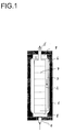
- Fig. 1 shows an example of a reactor 1 according to the invention Longitudinal section with a bottle neck 8 at each end of the reactor, with internals 2, which are concentric, closed on both sides Form inner cylinder with a feed 4 in the Intermediate space 3 between the inner wall of the reactor and the internals 2 and a discharge 5 from that separated by the internals 2 Reaction space, with return means 6 from the upper part of the Space between the inner wall of the reactor and internals 2 to the bottom End of the reaction space separated by the internals 2 as well as with horizontal perforated plates 7, an example being a number is represented by seven perforated plates.
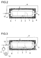
- FIG. 2 shows a further preferred embodiment variant in longitudinal section, which additionally has a return line for gas 9 from the upper area of the space between the reactor interior and Built-in components 2, the return line 9 to one below of the reactor arranged jet pump 10 leads through the liquid educt mixture is operated.
- Fig. 3 shows a further preferred embodiment in longitudinal section represents, the jet pump arranged below the reactor 10 additionally operated with a liquid reaction mixture will that from the lower part of the reactor using a circulating pump 11 withdrawn and fed to the jet pump, and the liquid reaction mixture first via a heat exchanger 12 is cooled.
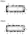
- the embodiment variant shown in longitudinal section in FIG. 4 additionally shows coils 13, which are applied to the internals 2 are and thus the space between the inner wall of the reactor and internals 2 as well as those separated by internals 2 Cool the interior of the reactor.
- FIG. 5 shows coils 13 only in the space between the inner wall of the reactor and internals 2 are arranged and thus predominantly this space cool.
- FIG. 6 shows an embodiment with three reaction spaces, by concentric arrangement of two cylindrical internals 2 are formed within the reactor 1.
- the invention Device exhibits lower investment and operating costs known devices.
- the following mathematical simulation illustrates the invention in more detail.
- the simulation is based on a kinetic model of the hydroformylation of polyisobutene, which was created by mathematically adapting a large number of experimental measurement results.
- a mixture of 80% by weight of an easily convertible, slightly branched polyisobutene A 1 and 20% by weight of a difficult to convert, more branched polyisobutene A 2 was assumed as the feed.
- a 10% excess of synthesis gas (molar ratio CO / H 2 1: 1), a reaction temperature of 130 ° C. and a pressure of 280 bar were used as a basis.
- reaction rates of the conversion of A 1 and A 2 to the respective hydroformylation product are proportional to the molar proportions of A 1 and A 2 , respectively.
- a dependence on the CO or H 2 concentration was neglected. It was assumed that the reaction volume does not change as a result of the reactions.
- the underlying mass flow of olefin feed and catalyst solution (aqueous cobalt (II) formate solution) was 6000 kg / h in each case.
Abstract
Description
Die Erfindung betrifft ein Verfahren zur Hydroformylierung von Olefinen mit wenigstens 6 Kohlenstoffatomen und eine Vorrichtung zur Durchführung des Verfahrens.The invention relates to a process for the hydroformylation of Olefins with at least 6 carbon atoms and a device to carry out the procedure.
Die Hydroformylierung oder Oxo-Synthese ist ein wichtiges großtechnisches Verfahren und dient der Herstellung von Aldehyden aus Olefinen, Kohlenmonoxid und Wasserstoff. Diese Aldehyde können gegebenenfalls im gleichen Arbeitsgang oder nachfolgend in einem getrennten Hydrierschritt mit Wasserstoff zu den entsprechenden Alkoholen hydriert werden. Die Hydroformylierung erfolgt in Anwesenheit von homogen im Reaktionsmedium gelösten Katalysatoren. Als Katalysatoren werden dabei im Allgemeinen die Carbonylkomplexe von Metallen der VIII. Nebengruppe, insbesondere Co, Rh, Ir, Pd, Pt oder Ru eingesetzt, die unmodifiziert oder z. B. mit aminoder phosphinhaltigen Liganden modifiziert sein können. Eine zusammenfassende Darstellung der großtechnisch ausgeübten Verfahren findet sich bei J. Falbe, "New Syntheses with Carbon Monoxide", Springer Verlag 1980, S. 162 ff.Hydroformylation or oxo synthesis is an important large-scale one Process and is used for the production of aldehydes Olefins, carbon monoxide and hydrogen. These aldehydes can if necessary in the same operation or subsequently in one separate hydrogenation step with hydrogen to the corresponding Alcohols are hydrogenated. The hydroformylation takes place in the presence of catalysts homogeneously dissolved in the reaction medium. The carbonyl complexes are generally used as catalysts of metals of subgroup VIII, in particular Co, Rh, Ir, Pd, Pt or Ru used, the unmodified or z. B. with aminoder phosphine-containing ligands can be modified. A summary Presentation of large-scale processes can be found in J. Falbe, "New Syntheses with Carbon Monoxide", Springer Verlag 1980, p. 162 ff.
Während kurzkettige Olefine vergleichsweise leicht hydroformyliert werden, bereitet die Hydroformylierung höherer Olefine mitunter Probleme. Dies liegt an der mit steigender Kettenlänge und zunehmenden Anteil an inneren, nicht endständigen Doppelbindungen abnehmenden Reaktionsgeschwindigkeit und außerdem an der Zunahme der Viskosität der Edukte und des Reaktionsgemisches. Zur Erzielung angemessener Umsätze sind daher lange Verweilzeiten notwendig, die jedoch infolge unerwünschter Nebenreaktionen, insbesondere der Bildung hochsiedender Reaktionsnebenprodukte, die Selektivität verschlechtern. Andererseits sind die Reinheitsanforderungen an das unmittelbare Verfahrensprodukt sehr hoch, weil dieses aufgrund seiner hohen Viskosität praktisch nicht auftrennbar ist und somit im Wesentlichen ohne weitere Reinigung eingesetzt werden muss. Die Verringerung des Reaktionsvolumens ist für die Wirtschaftlichkeit des Verfahrens von besonderer Bedeutung, da große Reaktionsvolumina bei den für die Verfahrensdurchführung vorgegebenen hohen Druckwerten sehr teuer sind. While short-chain olefins are comparatively easily hydroformylated sometimes prepares the hydroformylation of higher olefins Problems. This is due to the increasing chain length and increasing proportion of internal, non-terminal double bonds decreasing reaction rate and also increasing the viscosity of the starting materials and the reaction mixture. To achieve Adequate sales therefore require long dwell times, which, however, due to undesirable side reactions, in particular the formation of high-boiling reaction by-products, the selectivity deteriorate. On the other hand, the purity requirements to the immediate process product very high because of this due to its high viscosity practically inseparable and is therefore used essentially without further cleaning must become. The reduction in reaction volume is for that Economics of the process of particular importance because large reaction volumes for those carrying out the process predetermined high pressure values are very expensive.
Um das Reaktionsvolumen möglichst klein zu halten bzw. zur Erhöhung
der Raumzeitausbeute wurde daher vorgeschlagen, anstelle eines
total rückvermischten Reaktors (continuously stirred tank reactor,
CSTR) eine Reaktorkaskadierung einzusetzen. Eine Kaskadierung
kann durch verschiedene Maßnahmen erreicht werden, die jedoch
jeweils die im Folgenden aufgeführten Nachteile aufweisen:
Nach dem erfindungsgemäßen Verfahren lassen sich Olefine mit wenigstens 6, z. B. mit 9 bis 20, Kohlenstoffatomen hydroformylieren. Aus praktischen Gründen ist die Kettenlänge nach oben in der Regel bei etwa 700 Kohlenstoffatomen begrenzt. Das erfindungsgemäße Verfahren ist insbesondere für die Hydroformylierung von isomeren Olefingemischen geeignet, die durch Oligomerisierung von niederen Olefinen, wie Propen und Butenen, hergestellt werden. Zu den typischen Oligomerisaten, die als Ausgangsprodukte für das vorliegende Verfahren geeignet sind, zählen unter anderem Dimer-, Trimer- und Tetramerpropen, Dimer-, Trimer- und Tetramerbuten sowie Mischoligomerisate von Propenen und Butenen. Die Oligomerisate von Butenen sind nach bekannten Oligomerisierungsverfahren, z. B. nach dem Octol®-Prozess von Hüls und dem Dimersol®-Verfahren von IFP, großtechnisch zugänglich. Nach dem erfindungsgemäßen Verfahren können ferner lineare langkettige Olefine mit endständiger Doppelbindung, die z. B. nach dem SHOP®-Prozess oder Ziegler-Verfahren erhältlich sind, oder lineare langkettige Olefine mit innenliegender Doppelbindung hydroformyliert werden.According to the process of the invention, olefins can be at least 6, e.g. B. with 9 to 20, carbon atoms hydroformylate. For practical reasons, the chain length is up in the Usually limited to around 700 carbon atoms. The invention Process is especially for the hydroformylation of isomeric olefin mixtures suitable by oligomerization of lower olefins, such as propene and butenes, are produced. To the typical oligomerizates that are used as starting materials for the present methods are suitable include dimer, Trimer and tetramer propene, dimer, trimer and tetramer butene and Mixed oligomerizates of propenes and butenes. The oligomerizates of butenes are by known oligomerization processes, z. B. after the Octol® process by Hüls and the Dimersol® process from IFP, accessible on an industrial scale. According to the invention Processes can also use linear long chain terminal olefins Double bond, the z. B. according to the SHOP® process or Ziegler process are available, or linear long chain olefins be hydroformylated with an internal double bond.
Weitere bevorzugte Einsatzolefine sind im Wesentlichen einfach ungesättigte Polyalkylene mit 30 bis 700 Kohlenstoffatomen, wie insbesondere Polybuten oder Polyisobuten.Other preferred insert olefins are essentially simple unsaturated polyalkylenes with 30 to 700 carbon atoms, such as especially polybutene or polyisobutene.
Das erfindungsgemäße Verfahren findet unter homogener Katalyse statt. In der Regel wird hierzu mit dem Olefin und dem Synthesegas ein geeigneter Katalysator oder Katalysatorvorläufer in den Reaktor eingeführt. Bezüglich der eingesetzten Katalysatoren bzw. Katalysatorvorläufer gibt es keine wesentlichen Einschränkungen. In an sich bekannter Weise werden insbesondere Kobaltkatalysatoren, vorzugsweise Kobaltcarbonyle oder Kobaltcarbonylwasserstoff bzw. deren Vorläufer, wie insbesondere Kobalt(II)-salze, z. B. Kobalt(II)-formiat, Kobalt(II)-acetat oder Kobalt(II)-ethylhexanoat, eingesetzt.The process according to the invention takes place under homogeneous catalysis instead of. As a rule, this is done with the olefin and the synthesis gas a suitable catalyst or catalyst precursor in the Reactor introduced. Regarding the catalysts used or There are no significant restrictions on catalyst precursors. In a manner known per se, in particular cobalt catalysts, preferably cobalt carbonyls or cobalt carbonyl hydrogen or their precursors, such as in particular cobalt (II) salts, for. B. Cobalt (II) formate, cobalt (II) acetate or cobalt (II) ethylhexanoate, used.
Zweckmäßigerweise wird der Katalysator in gelöster Form im Einsatzolefin oder einem gegebenenfalls mitverwendeten organischen Lösungsmittel eingeführt. Hierzu kann man außerhalb des Reaktors eine wässrige Kobalt(II)-salzlösung mit Synthesegas in Kontakt bringen, wobei ein hydroformylierungsaktiver Kobaltkatalysator gebildet wird, und die den Kobaltkatalysator enthaltende wässrige Lösung gleichzeitig oder anschließend mit dem Einsatzolefin und/oder dem organischen Lösungsmittel in Kontakt bringen, wobei der Kobaltkatalysator in die organische Phase extrahiert wird.The catalyst is expediently dissolved in the feed olefin or an organic which may be used Solvent introduced. You can do this outside of the reactor an aqueous cobalt (II) salt solution in contact with synthesis gas bring, with a hydroformylation active cobalt catalyst is formed, and the aqueous containing the cobalt catalyst Solution at the same time or subsequently with the assignment olefin and / or bring into contact with the organic solvent, the Cobalt catalyst is extracted into the organic phase.
Die Vorab-Bildung des Katalysators erfolgt vorzugsweise bei Temperaturen von 50 bis 200 °C, insbesondere 100 bis 160 °C und unter Drucken von 100 bis 400 bar, insbesondere 200 bis 300 bar. Es eignen sich übliche Apparate für Gas-flüssig-Reaktionen, wie Rührbehälter mit Begasungsrührer, Blasensäulen oder Rieselbettkolonnen. Mit Vorteil erfolgt die Vorcarbonylierung in Gegenwart von Aktivkohle, Zeolithen oder basischen Ionenaustauschen, die mit Kobaltcarbonyl beladen sind, gemäß Beschreibung in der DE-OS 2139630. Aus der so erhaltenen, Kobalt(II)-salze und Kobaltkatalysator enthaltenden wässrigen Lösung wird dann der Kobaltkatalysator in die zu hydroformylierenden Olefinen und/oder das gegebenenfalls mitverwendete organische Lösungsmittel extrahiert.The catalyst is preferably formed beforehand at temperatures from 50 to 200 ° C, especially 100 to 160 ° C and below Pressure from 100 to 400 bar, in particular 200 to 300 bar. It are suitable devices for gas-liquid reactions, such as Stirring tank with gassing stirrer, bubble columns or trickle bed columns. The precarbonylation is advantageously carried out in the presence of activated carbon, zeolites or basic ion exchanges are loaded with cobalt carbonyl, as described in DE-OS 2139630. From the cobalt (II) salts and cobalt catalyst thus obtained containing aqueous solution then becomes the cobalt catalyst in the olefins to be hydroformylated and / or optionally extracted organic solvents extracted.
In vielen Fällen ist es im Hinblick auf den geringeren verfahrenstechnischen Aufwand bevorzugt, dass die Bildung des Kobaltkatalysators, die Extraktion des Kobaltkatalysators in die organische Phase und die Hydroformylierung der Olefine in einem Schritt erfolgen, indem die wässrige Kobalt(II)-salzlösung, die Olefine, Synthesegas und gegebenenfalls das organische Lösungsmittel gemeinsam in den Reaktor eingeführt werden. Die Ausgangsstoffe werden dabei so in die Reaktionszone eingebracht, dass eine gute Phasenvermischung erfolgt und eine möglichst hohe Phasenaustauschfläche erzeugt wird. Für die Dosierung können die dem Fachmann bekannten Dosiervorrichtungen, wie z. B. mit Füllkörpern befüllte Turbulenzrohre oder Mischdüsen für Mehrphasensysteme eingesetzt werden.In many cases it is due to the lower procedural Effort preferred that the formation of the cobalt catalyst, the extraction of the cobalt catalyst into the organic one Phase and the hydroformylation of the olefins in one step take place by the aqueous cobalt (II) salt solution, the olefins, Synthesis gas and optionally the organic solvent together be introduced into the reactor. The raw materials are introduced into the reaction zone in such a way that a good Phase mixing takes place and the largest possible phase exchange area is produced. For the dosage, the Dosing devices known to those skilled in the art, such as, for. B. with packing filled turbulence tubes or mixing nozzles for multiphase systems be used.
Zur Entfernung des Kobaltkatalysators wird der Reaktionsaustrag
geeigneterweise nach Verlassen der Reaktionszone auf Mitteldruck,
in der Regel 10 bis 30 bar, entspannt und in eine sogenannte Entkobaltungsstufe
geleitet. In der Entkobaltungsstufe wird der Reaktionsaustrag
in Gegenwart von wässriger, schwach saurer Kobalt(II)-salzlösung
mit Luft oder Sauerstoff bei Temperaturen von
vorzugsweise 90 bis 130 °C von Kobaltcarbonylkomplexen befreit.
Die Entkobaltung kann gewünschtenfalls in einem mit Füllkörpern,
wie z. B. Raschig-Ringen, befüllten Druckbehälter durchgeführt
werden, in dem eine möglichst hohe Phasenaustauschfläche erzeugt
wird. In einem nachgeschalteten Phasentrenngefäß wird die organische
Produktphase von der wässrigen Phase getrennt. Bei der Entkobaltung
wird der hydroformylierungsaktive Kobaltkatalysator unter
Bildung von Kobalt(II)-salzen, überwiegend Kobalt(II)-formiat,
zersetzt. Die wässrige Kobalt(II)-salzlösung wird zweckmäßigerweise
in die Reaktionszone bzw. Katalysatorbildungsstufe zurückgeführt.The reaction is discharged to remove the cobalt catalyst
suitably after leaving the reaction zone at medium pressure,
as a
Alternativ können Rhodiumkatalysatoren, die durch stickstoffoder phosphorhaltige Liganden modifiziert sein können, eingesetzt werden. Die Abtrennung des Rhodiumkatalysators vom Hydroformylierungsprodukt erfolgt im Allgemeinen durch Destillation, wobei der Rhodiumkatalysator zusammen mit hochsiedenden Bestandteilen als Rückstand verbleibt.Alternatively, rhodium catalysts can be produced by nitrogen or phosphorus-containing ligands can be used become. The separation of the rhodium catalyst from the hydroformylation product is generally carried out by distillation, the Rhodium catalyst together with high-boiling components as Residue remains.
Synthesegas ist ein großtechnisch zugängliches Gemisch von Kohlenmonoxid und Wasserstoff. Die Zusammensetzung des im erfindungsgemäßen Verfahren eingesetzten Synthesegases kann in weiten Bereichen variieren. Das molare Verhältnis von Kohlenmonoxid und Wasserstoff beträgt in der Regel etwa 10:1 bis 1:10, insbesondere 2,5:1 bis 1:2,5. Ein bevorzugtes Verhältnis liegt bei etwa 1:1,5.Synthesis gas is a commercially available mixture of carbon monoxide and hydrogen. The composition of the in the invention Synthesis gas used can vary widely Ranges vary. The molar ratio of carbon monoxide to Hydrogen is usually about 10: 1 to 1:10, in particular 2.5: 1 to 1: 2.5. A preferred ratio is about 1: 1.5.
Als gegebenenfalls mitzuverwendende organische Lösungsmittel kommen inerte Kohlenwasserstoffe, wie Paraffinfraktionen, aromatische Kohlenwasserstoffe, wie Benzol, Toluol oder Xylol, oder ein Aldehyd und/oder Alkohol, insbesondere aber das Hydroformylierungsprodukt des eingesetzten Olefins, in Betracht. Es können ferner hochsiedende Nebenprodukte der Hydroformylierung als Lösungsmittel verwendet werden. Die Mitverwendung eines Lösungsmittels kann z. B. zur Viskositätserniedrigung bei langkettigen Olefinen vorteilhaft sein.Possible organic solvents to be used inert hydrocarbons, such as paraffin fractions, aromatic Hydrocarbons such as benzene, toluene or xylene, or a Aldehyde and / or alcohol, but especially the hydroformylation product of the olefin used. It can also high-boiling by-products of hydroformylation as a solvent be used. The use of a solvent can e.g. B. for lowering the viscosity of long-chain olefins be beneficial.
Die Temperatur bei der Hydroformylierung liegt im Allgemeinen bei 100 bis 250 °C, insbesondere 145 bis 200 °C. Die Umsetzung wird vorzugsweise bei einem Druck im Bereich von 20 bis 400 bar, insbesondere 200 bis 300 bar, durchgeführt. The temperature during the hydroformylation is generally around 100 to 250 ° C, especially 145 to 200 ° C. The implementation will preferably at a pressure in the range from 20 to 400 bar, in particular 200 to 300 bar.
Das gegebenenfalls vorgewärmte Einsatzolefin, Synthesegas sowie gegebenenfalls Katalysator oder -vorläufer werden einem vertikalen, hochzylindrischen Reaktor zugeführt, der mindestens zwei Reaktionsräume aufweist. Erfindungsgemäß erstrecken sich die Reaktionsräume im Wesentlichen in Reaktorlängsrichtung und sind durch Auftrennung des Reaktorinnenraums mittels Einbauten, die entsprechend im Wesentlichen in Reaktorlängsrichtung angeordnet sind, gebildet. "Im Wesentlichen in Reaktorlängsrichtung" bedeutet, dass die Reaktionsräume ihre größte Raumausdehnung in Richtung der Reaktorlängsachse haben und die Länge eines Reaktionsraums mehr als 50 %, vorzugsweise mehr als 60 %, der Reaktorlänge beträgt. Die Einbauten bilden jeweils einen allseitig umschlossenen Reaktionsraum mit einer Zuführung für das Reaktionsgemisch an einem Ende und einer Abführung für das Reaktionsgemisch am entgegengesetzten Ende. Das Reaktionsgemisch wird somit zunächst einem ersten Reaktionsraum von unten zugeführt, es durchströmt denselben von unten nach oben und wird am oberen Ende desselben über geeignete Rückführungsmittel einem zweiten Reaktionsraum an dessen unteren Ende zugeführt. Aus diesem zweiten Reaktionsraum kann das Reaktionsgemisch nach außen abgeführt werden, es besteht aber auch die Möglichkeit, den Reaktor und das Verfahren so auszubilden, dass das Reaktionsgemisch vom oberen Ende des zweiten Reaktionsraums über Rückführungsmittel dem unterem Ende eines dritten Reaktionsraums zugeführt wird, gegebenenfalls in analoger Weise weitere Reaktionsräume durchströmt und schließlich vom oberen Teil des letzten Reaktionsraums nach außen geführt wird.The possibly preheated feed olefin, synthesis gas and if appropriate, catalyst or precursor are placed in a vertical, highly cylindrical reactor supplied, the at least two reaction spaces having. According to the invention, the reaction spaces extend essentially in the longitudinal direction of the reactor and are through Separation of the reactor interior by means of internals, which accordingly are arranged essentially in the longitudinal direction of the reactor, educated. "Essentially in the longitudinal direction of the reactor" means that the reaction spaces are their largest expansion in the direction the longitudinal axis of the reactor and the length of a reaction space more than 50%, preferably more than 60%, of the reactor length. The internals each form an enclosed space on all sides Reaction space with a feed for the reaction mixture on one End and a discharge for the reaction mixture on the opposite The End. The reaction mixture is thus one first reaction chamber supplied from below, it flows through the same from bottom to top and is over at the top of it suitable recycling means in a second reaction chamber fed lower end. For this second reaction space the reaction mixture are discharged to the outside, but it exists also the possibility to design the reactor and the process in such a way that the reaction mixture from the top of the second reaction space via return means the lower end of a third Reaction space is supplied, optionally in an analogous manner flows through further reaction spaces and finally from the upper Part of the last reaction space is led outside.
Die Einbauten sind bevorzugt als beidseitig geschlossene Zylinder ausgebildet, die jeweils an den beiden entgegengesetzten Enden Zu- bzw. Abführöffnungen aufweisen. Bezüglich der Anordnung der Einbauten im Reaktorquerschnitt gibt es grundsätzlich keine Einschränkungen; die Einbauten können nebeneinander, bevorzugt gleichmäßig über den Reaktorquerschnitt verteilt, besonders bevorzugt aber konzentrisch zueinander und zum Reaktormantel angeordnet sein.The internals are preferably closed cylinders on both sides formed, each at the two opposite ends Have feed or discharge openings. Regarding the arrangement of the There are basically no restrictions on internals in the reactor cross-section; the internals can be next to each other, preferably evenly distributed over the reactor cross-section, particularly preferred but arranged concentrically to each other and to the reactor jacket his.
In einer bevorzugten Ausführungsform bilden die Einbauten einen einzigen beidseitig geschlossenen Innenzylinder mit Zuführung am unteren Ende und Abführung am oberen Ende desselben. Das Reaktionsgemisch wird besonders bevorzugt zunächst dem Zwischenraum zwischen Reaktorinnenwand und Einbauten zugeführt, am oberen Ende des Zwischenraums über Rückführungsmittel einem zweiten Reaktionsraum an dessen unteren Ende zugeführt, am oberen Ende desselben gegebenenfalls in weitere Reaktionsräume von unten nach oben und schließlich nach außen abgeführt. In a preferred embodiment, the internals form one only inner cylinder closed on both sides with feed on lower end and discharge at the upper end of the same. The reaction mixture is particularly preferred first the space fed between the inner wall of the reactor and internals, at the upper end of the intermediate space via feedback means to a second reaction space fed at its lower end, at its upper end optionally in further reaction spaces from bottom to top and finally discharged to the outside.
In dieser Ausführungsform dient der zweite Reaktionsraum somit als Nachreaktionszone, d. h. zur Vervollständigung des im ersten Reaktionsraum erzielten Olefinumsatzes ohne unerwünschte Rückvermischung mit dem Inhalt des ersten Reaktionsraums.In this embodiment, the second reaction space thus serves as a post-reaction zone, d. H. to complete the first Reaction space achieved olefin conversion without undesirable backmixing with the content of the first reaction space.
Gemäß einer möglichen Ausführungsvariante kann nicht umgesetztes Synthesegas vom Gasraum am oberen Ende eines oder mehrerer Reaktionsräume mit Ausnahme des letzten Reaktionsraums entnommen, z. B. abgesaugt, verdichtet und dem Reaktor von unten erneut zugeführt werden. Diese Maßnahme kann unabhängig von der Zahl der vorhandenen Reaktionsräume angewendet werden. Sind lediglich zwei Reaktionsräume vorhanden, so wird nicht umgesetztes Synthesegas z. B. aus dem oberen Bereich des Zwischenraums zwischen Reaktorinnenwand und Einbauten abgezogen und demselben Reaktionsraum in dessen unteren Bereich erneut zugeführt. Bei mehr als zwei Reaktionsräumen kann nicht umgesetztes Gas einem oder mehreren der Reaktionsräume jeweils in dessen oberem Teil abgezogen werden, nicht jedoch dem Reaktionsraum, der als letzter vom Reaktionsgemisch durchströmt wird. Die Rückführung von Synthesegas erhöht die Turbulenz im ersten Reaktionsraum und sorgt für einen innigen Kontakt der Gas- und Flüssigphase.According to a possible embodiment variant, this cannot be implemented Syngas from the gas space at the top of one or more reaction spaces taken with the exception of the last reaction space, z. B. suctioned off, compressed and fed to the reactor again from below become. This measure can be done regardless of the number of existing reaction spaces can be used. Are only two Reaction spaces available, so unreacted synthesis gas z. B. from the upper region of the space between the reactor inner wall and internals deducted and the same reaction space fed again in its lower area. With more than two reaction rooms can be one or more of the unreacted gas Reaction spaces are deducted in the upper part of each, but not the reaction chamber, which is the last of the reaction mixture is flowed through. The recycle of synthesis gas increases the turbulence in the first reaction space and ensures an intimate Contact of the gas and liquid phases.
Die Verdichtung des rückgeführten, nicht umgesetzten Synthesegases kann vorteilhaft mittels einer Strahlpumpe erfolgen, wobei es besonders günstig ist, die Strahlpumpe mit dem Olefin und frisch zugeführtes Synthesegas umfassenden Eduktstrom zu betreiben. Die Strahlpumpe kann im unteren Bereich des Reaktors angeordnet sein, es ist jedoch auch möglich, dieselbe unterhalb des Reaktors, außerhalb desselben anzuordnen.The compression of the recycled, unreacted synthesis gas can advantageously be done by means of a jet pump, whereby it is particularly cheap, the jet pump with the olefin and fresh to operate supplied synthesis gas comprehensive feed stream. The Jet pump can be arranged in the lower region of the reactor, however, it is also possible to place it below the reactor, outside to arrange it.
Gemäß einer weiteren Ausführungsvariante ist es möglich, die Strahlpumpe zusätzlich zum Eduktstrom mit teilumgesetztem Reaktionsgemisch, das z. B. mittels einer Kreislaufpumpe am unteren Ende des ersten Reaktionsraums aus dem Reaktor abgesaugt wird, zu betreiben. Besonders bevorzugt kann das abgesaugte Reaktionsgemisch vor der Zuführung zur Strahlpumpe zwecks Wärmeabführung zunächst über einen Wärmetauscher geführt werden.According to a further embodiment variant, it is possible to Jet pump in addition to the educt flow with partially converted reaction mixture, the Z. B. by means of a circulation pump at the bottom End of the first reaction chamber is sucked out of the reactor operate. The suctioned reaction mixture can be particularly preferred before feeding to the jet pump for heat dissipation be passed through a heat exchanger.
Zwischen den einzelnen Reaktionsräumen im Inneren des Reaktors sind Rückführungsmittel vorgesehen, die jeweils das Reaktionsgemisch vom oberen Ende eines Reaktionsraums zum unteren Ende eines nächsten Reaktionsraums führen. Diese Rückführungsmittel sind besonders bevorzugt als Fallrohre oder Syphone ausgebildet. Die Fallrohre sind so ausgebildet, dass durch ihre obere Kante der Flüssigkeitsstand, d. h. die Flüssig-Gas-Phasengrenze, im entsprechenden Reaktionsraum konstant gehalten wird. Sollte der Flüssigkeitsstand unter die Oberkante des Fallrohrs sinken, wird aufgrund des sich aufbauenden Gasdrucks vermehrt nicht umgesetztes Synthesegas über das Fallrohr in den nächsten Reaktionsraum geleitet, bis der Flüssigkeitsstand wieder die Oberkante des Fallrohrs erreicht, und umgekehrt. Auf diese Weise wird eine Pegelsteuerung ohne aufwendige technische Maßnahmen erreicht.Between the individual reaction spaces inside the reactor recycling means are provided, each of which is the reaction mixture from the top of a reaction space to the bottom of a lead next reaction room. These return agents are special preferably designed as downpipes or syphones. The Downpipes are designed so that the upper edge of the Fluid level, d. H. the liquid-gas phase boundary, in the corresponding Reaction space is kept constant. Should the Liquid level will drop below the top edge of the downpipe due to the building up of gas pressure more and more unreacted Syngas through the downpipe into the next reaction space passed until the liquid level again the upper edge of the Down pipe reached, and vice versa. In this way, level control achieved without complex technical measures.
Der hochzylindrische Reaktor weist bevorzugt einen Schlankheitsgrad, d. h. ein Verhältnis von Länge zu Durchmesser, 1/d von etwa 3:1 bis 30:1, insbesondere von etwa 5:1 bis 10:1 auf.The high-cylindrical reactor preferably has a slenderness ratio, d. H. a ratio of length to diameter, 1 / d of about 3: 1 to 30: 1, in particular from about 5: 1 to 10: 1.
Die Einbauten im Reaktor sind bevorzugt in der Weise dimensioniert, dass das Verhältnis des Volumens des ersten Reaktionsraums zu dem des zweiten Reaktionsraums bzw. zweier weiterer aufeinanderfolgender Reaktionsräume 4:1 bis 1:4, bevorzugt 1,5:1 bis 1:1,5, besonders bevorzugt etwa 1:1 beträgt.The internals in the reactor are preferably dimensioned in such a way that the ratio of the volume of the first reaction space to that of the second reaction space or two further successive ones Reaction spaces 4: 1 to 1: 4, preferably 1.5: 1 to 1: 1.5, particularly preferably about 1: 1.
Die Dimensionierung der Einbauten in die Längsrichtung ist in der Weise ausgestaltet, dass die Höhe des zweiten Reaktionsraums (der weiteren Reaktionsräume) mehr als 50 %, insbesondere mehr als 60 %, der Höhe des Reaktors, besonders bevorzugt 80 bis 95 % der Höhe des Reaktors beträgt.The dimensioning of the internals in the longitudinal direction is in the Configured such that the height of the second reaction space (the other reaction spaces) more than 50%, in particular more than 60%, the height of the reactor, particularly preferably 80 to 95% of the Height of the reactor is.
Bevorzugt kann eine zusätzliche Kaskadierung des letzten Reaktionsraums, z. B. des zweiten Reaktionsraums, mittels horizontaler diffusionshemmender Einrichtungen, z. B. Lochbleche, die vorzugsweise äquidistant zueinander angeordnet sind, erreicht werden. Die Anzahl der Lochbleche kann 1 bis 10, besonders bevorzugt 3 bis 5 betragen. Diese Maßnahme wirkt sich umsatzfördernd auf die Hydroformylierungsreaktion aus, so dass eine weitere Umsatzsteigerung bei gegebenem Reaktionsvolumen erreicht werden kann. Die horizontalen Lochbleche können vorteilhaft außerhalb des Reaktors in die die weiteren Reaktionsräume bildenden Einbauten montiert werden, so dass die Montagekosten deutlich reduziert werden. Sie können dabei sowohl lösbar, durch entsprechende Flanschverbindungen montiert, oder aber direkt mit den Einbauten verschweißt werden.An additional cascading of the last reaction space, z. B. the second reaction chamber, by means of horizontal anti-diffusion devices, e.g. B. perforated sheets, preferably are arranged equidistant to each other can be achieved. The number of perforated plates can be 1 to 10, particularly preferred 3 to 5. This measure has a positive effect on sales the hydroformylation reaction, so that a further increase in sales can be achieved with a given reaction volume. The horizontal perforated plates can advantageously outside of Reactor in the internals forming the other reaction spaces be installed, so that the assembly costs are significantly reduced become. They can both be solved by appropriate Flange connections mounted, or directly with the internals be welded.
Der erfindungsgemäße Reaktor kann in seinem Inneren Mittel zur indirekten Kühlung der Reaktionsräume aufweisen. Derartige Mittel sind bevorzugt insbesondere im ersten, vom Reaktionsgemisch durchströmten Reaktionsraum vorgesehen. Sie können bevorzugt als Rohrschlangen, die von einem Kühlmedium durchströmt werden, ausgebildet sein, wobei die Rohrschlangen auf den Einbauten aufgebracht, z. B. aufgeschweißt, oder beabstandet dazu angeordnet sein können.The inside of the reactor according to the invention can have means for have indirect cooling of the reaction spaces. Such means are preferred, especially in the first, of the reaction mixture flowed reaction chamber provided. You can prefer as Coils, through which a cooling medium flows, are formed be, with the coils applied to the internals, z. B. welded, or spaced apart could be.
Die Erfindung wird im Folgenden anhand einer Zeichnung und von
Ausführungsbeispielen näher verdeutlicht:
Figur 1- die schematische Darstellung einer bevorzugten Ausführungsform einer erfindungsgemäßen Vorrichtung im Längsschnitt,
Figur 2- eine weitere bevorzugte Ausführungsform einer erfindungsgemäßen Vorrichtung im Längsschnitt mit Gasrückführung über eine Strahlpumpe,
Figur 3- eine weitere Ausgestaltung der Vorrichtung aus Figur 2 mit zusätzlicher Rückführung eines Teils des Reaktionsgemisches über die Strahlpumpe,
Figur 4- eine weitere bevorzugte Ausgestaltung im Längsschnitt mit auf den Einbauten aufgebrachten Rohrschlangen,
Figur 5- eine Ausführungsvariante mit Rohrschlangen, die nicht auf den Einbauten aufgebracht sind,
Figur 6- eine Ausführungsvariante mit drei Reaktionsräumen im Längsschnitt sowie im Querschnitt (Figur 6a) und
- Figur 7a
- einen Querschnitt durch einen erfindungsgemäßen Reaktor mit nicht konzentrischen Einbauten.
- Figure 1
- the schematic representation of a preferred embodiment of a device according to the invention in longitudinal section,
- Figure 2
- another preferred embodiment of a device according to the invention in longitudinal section with gas recirculation via a jet pump,
- Figure 3
- 2 shows a further embodiment of the device from FIG. 2 with additional recycling of part of the reaction mixture via the jet pump,
- Figure 4
- another preferred embodiment in longitudinal section with pipe coils applied to the internals,
- Figure 5
- a variant with pipe coils that are not attached to the internals,
- Figure 6
- an embodiment variant with three reaction spaces in longitudinal section and in cross section (Figure 6a) and
- Figure 7a
- a cross section through a reactor according to the invention with non-concentric internals.
In den Figuren werden gleiche Merkmale mit gleichen Bezugsziffern bezeichnet.The same features are given the same reference numbers in the figures designated.
Fig. 1 zeigt beispielhaft einen erfindungsgemäßen Reaktor 1 im
Längsschnitt mit jeweils einem Flaschenhals 8 an beiden Reaktorenden,
mit Einbauten 2, die einen konzentrischen, beidseitig geschlossenen
Innenzylinder bilden mit einer Zuführung 4 in den
Zwischenraum 3 zwischen der Reaktorinnenwand und den Einbauten 2
und einer Abführung 5 aus dem durch die Einbauten 2 abgetrennten
Reaktionsraum, mit Rückführungsmittel 6 aus dem oberen Teil des
Zwischenraums zwischen Reaktorinnenwand und Einbauten 2 zum unteren
Ende des durch die Einbauten 2 abgetrennten Reaktionsraums
sowie mit horizontalen Lochblechen 7, wobei beispielhaft eine Anzahl
von sieben Lochblechen dargestellt ist.Fig. 1 shows an example of a
Fig. 2 zeigt eine weitere bevorzuge Ausführungsvariante im Längsschnitt,
die zusätzlich eine Rückführleitung für Gas 9 aus dem
oberen Bereich des Zwischenraums zwischen Reaktorinnenraum und
Einbauten 2 aufweist, wobei die Rückführleitung 9 zu einer unterhalb
des Reaktors angeordneten Strahlpumpe 10 führt, die durch
das flüssige Eduktgemisch betrieben wird.2 shows a further preferred embodiment variant in longitudinal section,
which additionally has a return line for
Fig. 3 stellt eine weitere bevorzugte Ausführungsform im Längsschnitt
dar, wobei die unterhalb des Reaktors angeordnete Strahlpumpe
10 zusätzlich mit flüssigem Reaktionsgemisch betrieben
wird, dass aus dem unteren Teil des Reaktors mittels einer Kreislaufpumpe
11 abgezogen und der Strahlpumpe zugeführt wird, und
das flüssige Reaktionsgemisch zunächst über einen Wärmetauscher
12 gekühlt wird.Fig. 3 shows a further preferred embodiment in longitudinal section
represents, the jet pump arranged below the
Die in Fig. 4 im Längsschnitt dargestellte Ausführungsvariante
zeigt zusätzlich Rohrschlangen 13, die auf den Einbauten 2 aufgebracht
sind und somit den Zwischenraum zwischen Reaktorinnenwand
und Einbauten 2 wie auch den durch die Einbauten 2 abgetrennten
Reaktorinnenraum kühlen.The embodiment variant shown in longitudinal section in FIG. 4
additionally shows
Demgegenüber zeigt die Ausführungsvariante in Fig. 5 Rohrschlangen
13 die lediglich im Zwischenraum zwischen Reaktorinnenwand
und Einbauten 2 angeordnet sind und somit überwiegend diesen Zwischenraum
kühlen.In contrast, the embodiment variant in FIG. 5 shows coils
13 only in the space between the inner wall of the reactor
and
Fig. 6 zeigt ein Ausführungsbeispiel mit drei Reaktionsräumen,
die durch konzentrische Anordnung von zwei zylindrischen Einbauten
2 innerhalb des Reaktors 1 gebildet werden. Der Querschnitt
A/A durch den in Fig. 6 dargestellten Reaktor (Fig. 6a) verdeutlicht
die konzentrische Anordnung der Einbauten 2.6 shows an embodiment with three reaction spaces,
by concentric arrangement of two
Fig. 7a zeigt demgegenüber einen Querschnitt durch einen Reaktor
mit drei im Reaktor 1 angeordneten nicht konzentrischen Einbauten
2. 7a, on the other hand, shows a cross section through a reactor
with three non-concentric internals arranged in the
Erfindungsgemäß wird somit ein Verfahren zur Verfügung gestellt, dass sich durch eine verbesserte Raumzeitausbeute, eine Erhöhung von Umsatz und Selektivität, auszeichnet. Die erfindungsgemäße Vorrichtung weist niedrigere Investitions- und Betriebskosten gegenüber bekannten Vorrichtungen aus.According to the invention, a method is thus made available that by an improved space-time yield, an increase of sales and selectivity. The invention Device exhibits lower investment and operating costs known devices.
Besonders vorteilhaft ist die Verbesserung des Stoffaustauschs zwischen flüssigem Reaktionsmedium und Gasphase infolge der erfindungsgemäßen Aufteilung des Reaktorquerschnittes in mehrere Zonen durch die im Wesentlichen im Reaktionslängsrichtung angeordneten Einbauten. Dadurch wird in den Zonen eine Vergrößerung der Querschnittsbelastung erreicht mit der Folge eines verbesserten Stoffaustausches. Dadurch können die bei bekannten Vorrichtungen sehr geringen Gasgehalte und Stoffaustauschflächen ohne den Einsatz von rotierenden Teilen, beispielsweise von Rührern, auf ein mehrfaches gesteigert werden. Die Nachteile, die mit dem Einsatz rotierender Teile, insbesondere bei Hochdruckapparaten verbunden sind, können so vermieden werden.Improving the exchange of materials is particularly advantageous between liquid reaction medium and gas phase as a result of the invention Division of the reactor cross-section into several Zones arranged essentially in the longitudinal direction of the reaction Internals. This causes an enlargement in the zones the cross-sectional load achieved with the consequence of an improved Mass transfer. This allows the known devices very low gas contents and mass transfer areas without the use of rotating parts, such as stirrers, can be increased to a multiple. The disadvantages with the Use of rotating parts, especially in high pressure equipment connected can be avoided.
Die Erfindung wird durch die folgende mathematische Simulation näher veranschaulicht. Die Simulation beruht auf einem kinetischen Modell der Hydroformylierung von Polyisobuten, das erstellt worden ist, indem eine Vielzahl experimenteller Messergebnisse mathematisch angepasst wurde. Als Zulauf wurde ein Gemisch von 80 Gew.-% eines leicht umsetzbaren, gering verzweigten Polyisobutens A1 und 20 Gew.-% eines schwer umsetzbaren, stärker verzweigten Polyisobutens A2 unterstellt. Es wurde ein 10%iger Überschuss an Synthesegas (molares Verhältnis CO/H2 1:1), eine Reaktionstemperatur von 130 °C und ein Druck von 280 bar zugrunde gelegt. Es wurde angenommen, dass die Reaktionsgeschwindigkeiten der Umsetzung von A1 und A2 zum jeweiligen Hydroformylierungsprodukt proportional den Molanteilen von A1 bzw. A2 sind. Eine Abhängigkeit von der CO- bzw. H2-Konzentration wurde vernachlässigt. Es wurde unterstellt, dass sich durch die Reaktionen das Reaktionsvolumen nicht verändert. Der zugrunde gelegte Massenstrom an Olefinzulauf und Katalysatorlösung (wässrige Kobalt(II)-formiatlösung) betrug jeweils 6000 kg/h.The following mathematical simulation illustrates the invention in more detail. The simulation is based on a kinetic model of the hydroformylation of polyisobutene, which was created by mathematically adapting a large number of experimental measurement results. A mixture of 80% by weight of an easily convertible, slightly branched polyisobutene A 1 and 20% by weight of a difficult to convert, more branched polyisobutene A 2 was assumed as the feed. A 10% excess of synthesis gas (molar ratio CO / H 2 1: 1), a reaction temperature of 130 ° C. and a pressure of 280 bar were used as a basis. It was assumed that the reaction rates of the conversion of A 1 and A 2 to the respective hydroformylation product are proportional to the molar proportions of A 1 and A 2 , respectively. A dependence on the CO or H 2 concentration was neglected. It was assumed that the reaction volume does not change as a result of the reactions. The underlying mass flow of olefin feed and catalyst solution (aqueous cobalt (II) formate solution) was 6000 kg / h in each case.
Im Fall I wurde ein Reaktor ohne Einbauten mit einem Volumen von 30 m3 und vollkommener Rückvermischung betrachtet. Im Fall II war der Reaktor in vier ideal durchmischte Teilstufen mit einem jeweiligen Volumen von 15 m3, 5 m3, 5 m3 und 5 m3 aufgeteilt. Die Eintrittskonzentrationen des Olefinzulaufs sowie die Katalysatormengen sind in beiden Reaktorkonfigurationen gleich.In case I, a reactor without internals with a volume of 30 m 3 and complete backmixing was considered. In case II, the reactor was divided into four ideally mixed sub-stages with a volume of 15 m 3 , 5 m 3 , 5 m 3 and 5 m 3 . The inlet concentrations of the olefin feed and the amounts of catalyst are the same in both reactor configurations.
Die erhaltenen Ergebnisse sind in der folgenden Tabelle zusammengefasst.
Ersichtlich sind bei der erfindungsgemäßen Kaskadierung des Reaktors bei gleichem Reaktionsvolumen sowohl die Einzelumsätze als auch der Gesamtumsatz höher.Can be seen in the cascading of the reactor according to the invention with the same reaction volume both the individual sales as total sales also higher.
Claims (10)
Applications Claiming Priority (2)
| Application Number | Priority Date | Filing Date | Title |
|---|---|---|---|
| DE10106482A DE10106482A1 (en) | 2001-02-13 | 2001-02-13 | hydroformylation |
| DE10106482 | 2001-02-13 |
Publications (2)
| Publication Number | Publication Date |
|---|---|
| EP1231198A1 true EP1231198A1 (en) | 2002-08-14 |
| EP1231198B1 EP1231198B1 (en) | 2005-10-12 |
Family
ID=7673772
Family Applications (1)
| Application Number | Title | Priority Date | Filing Date |
|---|---|---|---|
| EP02003057A Expired - Lifetime EP1231198B1 (en) | 2001-02-13 | 2002-02-12 | Hydroformylation |
Country Status (4)
| Country | Link |
|---|---|
| US (2) | US7015361B2 (en) |
| EP (1) | EP1231198B1 (en) |
| JP (1) | JP3980366B2 (en) |
| DE (2) | DE10106482A1 (en) |
Cited By (11)
| Publication number | Priority date | Publication date | Assignee | Title |
|---|---|---|---|---|
| EP1338333A1 (en) * | 2002-02-14 | 2003-08-27 | Basf Aktiengesellschaft | Reactor cascade with a main reactor and a second reactor |
| US7321068B2 (en) | 2003-12-09 | 2008-01-22 | Basf Aktiengesellschaft | Method for producing tricyclodecandialdehyde |
| US7615645B2 (en) | 2003-10-21 | 2009-11-10 | Basf Aktiengesellschaft | Method for the continuous production of aldehydes |
| WO2013153136A1 (en) | 2012-04-12 | 2013-10-17 | Basf Se | Method for replenishing the catalyst in continuous hydroformylation |
| US8889917B2 (en) | 2012-04-12 | 2014-11-18 | Basf Se | Method of supplementing the catalyst in continuous hydroformylation |
| WO2018228879A1 (en) | 2017-06-13 | 2018-12-20 | Basf Se | Hydroformylation process for producing 1,6-hexanediol derivatives |
| US10315975B2 (en) | 2015-07-10 | 2019-06-11 | Basf Se | Method for the hydroformylation of 2-substituted butadienes and the production of secondary products thereof, especially ambrox |
| WO2020048986A1 (en) | 2018-09-05 | 2020-03-12 | Basf Se | Reactor for carrying out a reaction between two non-miscible fluids of different densities |
| WO2020048998A1 (en) | 2018-09-05 | 2020-03-12 | Basf Se | Method for carrying out a gas/fluid two-phase high-pressure reaction |
| US10647651B2 (en) | 2015-10-12 | 2020-05-12 | Basf Se | Hydroformylation process for producing 1,6-disubstituted hexane derivatives |
| WO2021160448A1 (en) | 2020-02-11 | 2021-08-19 | Basf Se | Low-pressure hydroformylation of diisobutene |
Families Citing this family (6)
| Publication number | Priority date | Publication date | Assignee | Title |
|---|---|---|---|---|
| US7684147B2 (en) * | 2003-12-15 | 2010-03-23 | Univ Bar Ilan | Magnetoelectronic devices based on colossal magnetoresistive thin films |
| DE102004021128A1 (en) * | 2004-04-29 | 2005-11-24 | Oxeno Olefinchemie Gmbh | Apparatus and method for the continuous reaction of a liquid with a gas on a solid catalyst |
| JP5468538B2 (en) * | 2007-05-29 | 2014-04-09 | エルジー・ケム・リミテッド | Olefin hydroformylation process and apparatus used therefor |
| KR101206214B1 (en) | 2009-01-16 | 2012-12-03 | 주식회사 엘지화학 | System For Producing Alcohol From Olefin |
| DE102016208843A1 (en) * | 2016-05-23 | 2017-11-23 | Siemens Aktiengesellschaft | Reactor with a jet pump and method of increasing the pressure of a reactant with a jet pump |
| WO2020048991A1 (en) * | 2018-09-05 | 2020-03-12 | Basf Se | Reactor for carrying out a gas-liquid two-phase high-pressure reaction with a foaming medium |
Citations (4)
| Publication number | Priority date | Publication date | Assignee | Title |
|---|---|---|---|---|
| DE926846C (en) * | 1952-08-17 | 1955-04-25 | Chemische Verwertungsgesellsch | Process for carrying out exothermic reactions in which gases or vapors and liquids are involved |
| US3929900A (en) * | 1972-12-27 | 1975-12-30 | Ruhrchemie Ag | Continuous process for the production of oxygen containing compounds |
| DE3220858A1 (en) * | 1982-06-03 | 1983-12-08 | Basf Ag, 6700 Ludwigshafen | Process for the hydroformylation of olefinically unsaturated compounds |
| EP1057524A2 (en) * | 1999-06-02 | 2000-12-06 | Oxeno Olefinchemie GmbH | Process to perform catalysed multiphase reactions, especially hydroformylation |
Family Cites Families (8)
| Publication number | Priority date | Publication date | Assignee | Title |
|---|---|---|---|---|
| FR2038694A5 (en) * | 1969-03-27 | 1971-01-08 | Progil | |
| US3988117A (en) * | 1972-12-27 | 1976-10-26 | Ruhrchemie Aktiengesellschaft | Reactor for the production of oxygen containing compounds |
| JPS5898101A (en) * | 1981-12-04 | 1983-06-10 | Toyo Eng Corp | Gas-liquid contact apparatus |
| EP0132224A1 (en) * | 1983-06-24 | 1985-01-23 | Ciba-Geigy Ag | Bubble column reactor for gas-liquid exchange reactions |
| GB2177616B (en) * | 1985-07-09 | 1988-07-06 | Smidth & Co As F L | Gas suspension reactor |
| US5855741A (en) * | 1990-02-06 | 1999-01-05 | Koch Engineering Company, Inc. | Apparatus for concurrent reaction with distillation |
| US5731473A (en) | 1995-12-06 | 1998-03-24 | Union Carbide Chemicals & Plastics Technology Corporation | Metal-ligand complex catalyzed processes |
| DE19854637A1 (en) * | 1998-11-26 | 2000-05-31 | Basf Ag | Reactor for the continuous implementation of gas-liquid, liquid-liquid or gas-liquid-solid reactions |
-
2001
- 2001-02-13 DE DE10106482A patent/DE10106482A1/en not_active Withdrawn
-
2002
- 2002-02-12 JP JP2002034464A patent/JP3980366B2/en not_active Expired - Fee Related
- 2002-02-12 DE DE50204499T patent/DE50204499D1/en not_active Expired - Lifetime
- 2002-02-12 EP EP02003057A patent/EP1231198B1/en not_active Expired - Lifetime
- 2002-02-13 US US10/073,248 patent/US7015361B2/en not_active Expired - Fee Related
-
2005
- 2005-09-06 US US11/218,532 patent/US7351384B2/en not_active Expired - Fee Related
Patent Citations (4)
| Publication number | Priority date | Publication date | Assignee | Title |
|---|---|---|---|---|
| DE926846C (en) * | 1952-08-17 | 1955-04-25 | Chemische Verwertungsgesellsch | Process for carrying out exothermic reactions in which gases or vapors and liquids are involved |
| US3929900A (en) * | 1972-12-27 | 1975-12-30 | Ruhrchemie Ag | Continuous process for the production of oxygen containing compounds |
| DE3220858A1 (en) * | 1982-06-03 | 1983-12-08 | Basf Ag, 6700 Ludwigshafen | Process for the hydroformylation of olefinically unsaturated compounds |
| EP1057524A2 (en) * | 1999-06-02 | 2000-12-06 | Oxeno Olefinchemie GmbH | Process to perform catalysed multiphase reactions, especially hydroformylation |
Cited By (13)
| Publication number | Priority date | Publication date | Assignee | Title |
|---|---|---|---|---|
| EP1338333A1 (en) * | 2002-02-14 | 2003-08-27 | Basf Aktiengesellschaft | Reactor cascade with a main reactor and a second reactor |
| US7615645B2 (en) | 2003-10-21 | 2009-11-10 | Basf Aktiengesellschaft | Method for the continuous production of aldehydes |
| US7321068B2 (en) | 2003-12-09 | 2008-01-22 | Basf Aktiengesellschaft | Method for producing tricyclodecandialdehyde |
| WO2013153136A1 (en) | 2012-04-12 | 2013-10-17 | Basf Se | Method for replenishing the catalyst in continuous hydroformylation |
| US8889917B2 (en) | 2012-04-12 | 2014-11-18 | Basf Se | Method of supplementing the catalyst in continuous hydroformylation |
| US10315975B2 (en) | 2015-07-10 | 2019-06-11 | Basf Se | Method for the hydroformylation of 2-substituted butadienes and the production of secondary products thereof, especially ambrox |
| US10647651B2 (en) | 2015-10-12 | 2020-05-12 | Basf Se | Hydroformylation process for producing 1,6-disubstituted hexane derivatives |
| WO2018228879A1 (en) | 2017-06-13 | 2018-12-20 | Basf Se | Hydroformylation process for producing 1,6-hexanediol derivatives |
| US10941092B2 (en) | 2017-06-13 | 2021-03-09 | Basf Se | Hydroformylation process for producing 1,6-hexanediol derivatives |
| WO2020048986A1 (en) | 2018-09-05 | 2020-03-12 | Basf Se | Reactor for carrying out a reaction between two non-miscible fluids of different densities |
| WO2020048998A1 (en) | 2018-09-05 | 2020-03-12 | Basf Se | Method for carrying out a gas/fluid two-phase high-pressure reaction |
| US11766653B2 (en) | 2018-09-05 | 2023-09-26 | Basf Se | Method for carrying out a gas/fluid two-phase high-pressure reaction |
| WO2021160448A1 (en) | 2020-02-11 | 2021-08-19 | Basf Se | Low-pressure hydroformylation of diisobutene |
Also Published As
| Publication number | Publication date |
|---|---|
| US7351384B2 (en) | 2008-04-01 |
| US7015361B2 (en) | 2006-03-21 |
| JP3980366B2 (en) | 2007-09-26 |
| US20020159930A1 (en) | 2002-10-31 |
| JP2002249453A (en) | 2002-09-06 |
| US20060004231A1 (en) | 2006-01-05 |
| DE50204499D1 (en) | 2006-02-23 |
| EP1231198B1 (en) | 2005-10-12 |
| DE10106482A1 (en) | 2002-08-14 |
Similar Documents
| Publication | Publication Date | Title |
|---|---|---|
| EP1669337B1 (en) | Method for the preparation of alcohols from alkenes by means of hydroformylation and hydrogenation | |
| EP1231198B1 (en) | Hydroformylation | |
| EP1204624B1 (en) | Continuous process for hydroformylating olefins with 6 to 20 carbon atoms | |
| EP1057524B1 (en) | Process to perform catalysed hydroformylations | |
| EP1674441B1 (en) | Process for the hydroformylation of olefins | |
| EP1114017B1 (en) | Method for producing aldehydes and/or alcohols or amines | |
| EP1106594B1 (en) | Process for the hydroformylation of olefins | |
| EP1106596B1 (en) | Process to perform aldolcondensations using catalysed multiphase reactions | |
| EP1279658B1 (en) | Process for the hydroformylation of higher olefins in presence of cobalt compounds as catalyst | |
| EP2188236B1 (en) | One-stage continuous process for hydroformylating higher olefins or olefin mixtures | |
| EP1485341A2 (en) | Method for the hydroformylation of olefins | |
| EP3394022B1 (en) | Cylindrical reactor and use thereof for continuous hydroformylation | |
| EP3492447B1 (en) | Method for the preparation of alcohols from aldehydes | |
| EP3492446B1 (en) | Method for the recovery of alcohols from aldehydes | |
| EP2220017A1 (en) | Multistage continuous method for hydroformylation of higher olefins or olefin mixtures | |
| DE102009027978A1 (en) | Process for the preparation of decanecarboxylic acids | |
| DE102008007080A1 (en) | Producing nine carbon alcohol from eight carbon olefin, comprises e.g. hydroformylating the olefin in the presence of cobalt catalyst, separating hydroformylation mixture to low boiling fraction having the olefin and converting the olefin | |
| DE102009016651B4 (en) | Process for the preparation of aldehydes | |
| EP3301084B1 (en) | Continuous process for producing 2-methylene aldehydes | |
| DE10227995A1 (en) | Process for the production of 7-17 C aliphatic alcohols comprises cobalt catalyzed hydroformylation of 3-16C olefins whereby the organic phase is extracted with a water containing liquid | |
| DE19643154A1 (en) | Process for the preparation of oxidation products of cyclohexane in countercurrent | |
| DE2653445C2 (en) | Process for the hydrogenation of 4-acetoxycrotonaldehyde-containing 1,4-diacetoxybutene-2 | |
| DE10241266A1 (en) | Production of 7-17C aliphatic alcohols, useful as solvents and precursors for detergents and plasticizers, comprises cobalt catalyzed hydroformylation of 6-16C olefins and oxidative decomposition of the catalyst in the presence of water | |
| DE2747302C2 (en) | Process for the continuous production of oxygen-containing compounds | |
| DE975064C (en) | Process for the production of alcohols |
Legal Events
| Date | Code | Title | Description |
|---|---|---|---|
| PUAI | Public reference made under article 153(3) epc to a published international application that has entered the european phase |
Free format text: ORIGINAL CODE: 0009012 |
|
| AK | Designated contracting states |
Kind code of ref document: A1 Designated state(s): AT BE CH CY DE DK ES FI FR GB GR IE IT LI LU MC NL PT SE TR |
|
| AX | Request for extension of the european patent |
Free format text: AL;LT;LV;MK;RO;SI |
|
| 17P | Request for examination filed |
Effective date: 20030213 |
|
| AKX | Designation fees paid |
Designated state(s): BE DE NL |
|
| 17Q | First examination report despatched |
Effective date: 20031014 |
|
| GRAP | Despatch of communication of intention to grant a patent |
Free format text: ORIGINAL CODE: EPIDOSNIGR1 |
|
| GRAS | Grant fee paid |
Free format text: ORIGINAL CODE: EPIDOSNIGR3 |
|
| GRAA | (expected) grant |
Free format text: ORIGINAL CODE: 0009210 |
|
| AK | Designated contracting states |
Kind code of ref document: B1 Designated state(s): BE DE NL |
|
| REF | Corresponds to: |
Ref document number: 50204499 Country of ref document: DE Date of ref document: 20060223 Kind code of ref document: P |
|
| PLBE | No opposition filed within time limit |
Free format text: ORIGINAL CODE: 0009261 |
|
| STAA | Information on the status of an ep patent application or granted ep patent |
Free format text: STATUS: NO OPPOSITION FILED WITHIN TIME LIMIT |
|
| 26N | No opposition filed |
Effective date: 20060713 |
|
| PGFP | Annual fee paid to national office [announced via postgrant information from national office to epo] |
Ref country code: NL Payment date: 20160225 Year of fee payment: 15 |
|
| PGFP | Annual fee paid to national office [announced via postgrant information from national office to epo] |
Ref country code: BE Payment date: 20160225 Year of fee payment: 15 |
|
| PG25 | Lapsed in a contracting state [announced via postgrant information from national office to epo] |
Ref country code: BE Free format text: LAPSE BECAUSE OF NON-PAYMENT OF DUE FEES Effective date: 20170228 |
|
| REG | Reference to a national code |
Ref country code: NL Ref legal event code: MM Effective date: 20170301 |
|
| PG25 | Lapsed in a contracting state [announced via postgrant information from national office to epo] |
Ref country code: NL Free format text: LAPSE BECAUSE OF NON-PAYMENT OF DUE FEES Effective date: 20170301 |
|
| REG | Reference to a national code |
Ref country code: BE Ref legal event code: MM Effective date: 20170228 |
|
| PGFP | Annual fee paid to national office [announced via postgrant information from national office to epo] |
Ref country code: DE Payment date: 20190426 Year of fee payment: 18 |
|
| REG | Reference to a national code |
Ref country code: DE Ref legal event code: R119 Ref document number: 50204499 Country of ref document: DE |
|
| PG25 | Lapsed in a contracting state [announced via postgrant information from national office to epo] |
Ref country code: DE Free format text: LAPSE BECAUSE OF NON-PAYMENT OF DUE FEES Effective date: 20200901 |