EP1227317B1 - Thermisches Analysegerät mit verteiltem Widerstand und integriertem Flansch zur Befestigung von verschiedenen Kühlvorrichtungen - Google Patents
Thermisches Analysegerät mit verteiltem Widerstand und integriertem Flansch zur Befestigung von verschiedenen Kühlvorrichtungen Download PDFInfo
- Publication number
- EP1227317B1 EP1227317B1 EP02001504.6A EP02001504A EP1227317B1 EP 1227317 B1 EP1227317 B1 EP 1227317B1 EP 02001504 A EP02001504 A EP 02001504A EP 1227317 B1 EP1227317 B1 EP 1227317B1
- Authority
- EP
- European Patent Office
- Prior art keywords
- calorimeter
- cooling
- longitudinal members
- cooling flange
- top surface
- Prior art date
- Legal status (The legal status is an assumption and is not a legal conclusion. Google has not performed a legal analysis and makes no representation as to the accuracy of the status listed.)
- Expired - Lifetime
Links
Images


Classifications
-
- G—PHYSICS
- G01—MEASURING; TESTING
- G01N—INVESTIGATING OR ANALYSING MATERIALS BY DETERMINING THEIR CHEMICAL OR PHYSICAL PROPERTIES
- G01N25/00—Investigating or analyzing materials by the use of thermal means
- G01N25/20—Investigating or analyzing materials by the use of thermal means by investigating the development of heat, i.e. calorimetry, e.g. by measuring specific heat, by measuring thermal conductivity
- G01N25/48—Investigating or analyzing materials by the use of thermal means by investigating the development of heat, i.e. calorimetry, e.g. by measuring specific heat, by measuring thermal conductivity on solution, sorption, or a chemical reaction not involving combustion or catalytic oxidation
- G01N25/4806—Details not adapted to a particular type of sample
- G01N25/4826—Details not adapted to a particular type of sample concerning the heating or cooling arrangements
Definitions
- the present invention relates to the field of instrumentation for differential thermal analysis and differential scanning calorimetry.
- Differential thermal analysis generally refers to a calorimetric technique for measuring physical properties of a substance by exposing the substance to different temperature regimes. DTA can be employed to measure parameters associated with phase transitions, glass transitions, polymerization/depolymerization, crystallization, softening, sublimation, dehydration, decomposition, oxidation, cure kinetics and so forth.
- a differential scanning calorimeter measures temperatures and heat flows associated with energy-emitting or energy-absorbing (exothermic and endothermic, respectively) material transitions. DSCs are widely used in academic, government and private facilities for research purposes, as well as for quality control and production purposes.
- DSC although it is to be understood to encompass DTA as well.
- Typical DSC instrumentation includes the following basic components: a heated measurement chamber enclosing a sensor assembly upon which the material to be evaluated (the “sample") may be placed; a furnace heater for heating the measurement chamber; and a cooling device.
- the cooling device acts as a heat sink for the furnace heater. The cooling device may find application when temperature in the measurement chamber is being increased or decreased.
- Typical DSC instrumentation also includes control circuitry for controlling the furnace heater/cooling device so as to conform the temperature in the measurement chamber to the programmed temperature profile.
- the DSC instrumentation may also include output means, such as a printer or video screen or plotter, to present the results of the measurements. Results can be presented as plots of temperature difference versus absolute temperature or heat flow (e.g., watts per gram) versus absolute temperature.
- the measurement chamber holds a sample of interest and a reference material, which are to be subjected to a programmed temperature profile.
- the reference material is typically inert over the profile of interest or otherwise well understood.
- DSC analyses generally do not use an actual reference material; rather, the reference pan is left empty.
- the sample and the reference material are placed on the DSC sensor assembly, which includes a sample position temperature detector and a reference material position temperature detector. These two temperature detectors are typically configured so that the temperature difference between the sample position and the reference material position can be directly measured.
- Figure 1b of Reading, et al., U.S. Pat. No. 5,224,775 (the '775 patent) provides an illustration of a basic DSC device.
- Figure 1 of Stone, U.S. Pat. No. 3,456,490 illustrates another configuration of a basic DSC device.
- the furnace heater and/or cooling device are controlled to follow the programmed temperature profile.
- the temperature difference ⁇ T (or heat flow into or out of) between the sample and the reference material is measured as a function of the measured sample temperature.
- the results, such as sudden excursions in the temperature difference ⁇ T when the sample changes phase or undergoes a chemical reaction, are studied to better understand the properties and behavior of the sample.
- PDSC Pressure Differential Scanning Calorimetry
- PDTA Pressure Differential Thermal Analysis
- DPC Differential Photocalorimetry
- PDPC Pressure Differential Photocalorimetry
- the temperature profile can range from the lowest to highest achievable value, e.g., -150°C to +725°C for the calorimeter disclosed in the '775 patent or -200°C to + 725°C for the calorimeter disclosed in U.S. Patent Application Serial No. 09/767903 filed on January 24, 2001 , as a continuation-in-part of U.S. Patent Application Serial Nos. 09/643,870 and 09/643,869 .
- Prior art DSC devices often entail unsatisfactory tradeoffs between such attributes.
- Prior art devices have other drawbacks. For example, it is desirable to keep the temperature of the measurement chamber uniform so that both the sample and the reference material are exposed to the same thermal stimulus. Yet, prior art designs are often susceptible to temperature variations or gradients in the measurement chamber. Such temperature nonuniformities are difficult to predict/measure so as to compensate for them through signal processing. These phenomena can lead to measurement errors.
- prior art designs have not readily lent themselves to a modular configuration that permits easy and rapid replacement of components to tailor the DSC instrumentation to the application. Even where prior art configurations might physically permit modular substitution of components (such as replacing a cooling device of a first type with a cooling device of a second type), the inherent design characteristics of prior art configurations may greatly limit the benefit of such modularity. For example, a DSC unit may permit a "cooling fin” device to be coupled to the measurement chamber/furnace heater to provide a heat sink during above-ambient "hot” measurements. The application is then changed so that substantially below-ambient "cold” measurements are desired.
- the prior art design may physically permit substituting the cooling fin with a high-powered "liquid cooled heat exchanger.”
- the prior art's design characteristics e.g., very inefficient heat transmission paths
- US 5 711 604 reports a method for the determination of thermal conductivity coefficients of solid state sample materials comprising the steps of heating a meltible calibration sample up to its melting temperature by raising the temperature of an analyzer at a controlled rate and causing heat to flow through a path having a certain thermal resistance to the calibration sample. The heating is performed one time with the solid sample material interposed in the path so that the heat is forced to flow through the path and through the solid sample material, and another time with the solid sample material being removed so that the heat flows only through the path. From comparison and analysis of the gained data the coefficient of thermal conductivity of the sample material can be determined with respect to its thickness.
- the disclosed differential scanning calorimeter comprises a heat sink made of a material having a good thermal conductivity, as well as a sample holder and a reference holder which are mounted within the sink by means of elements having identical thermal resistances. The temperature of both sample holders is measured by temperature sensors.
- US 5 655 681 discloses a further implementation of a calorimeter, being thermally insulated and comprising a vessel with an inner chamber containing a liquefied gas, with the vessel being formed of four walls arranged proximately in parallel, where each pair of adjacent walls delimits a space.
- Two partition walls are allocated between the inner wall and an outer wall which is exposed to atmosphere.
- the space between each pair of two partition walls contains a gas at atmospheric pressure, where the spacing is selected to minimize heat transfer from the atmosphere to the inner chamber.
- Such a device can be provided with a cover comprising a set of walls with spacing similar to those of the vessel.
- the heating is again established by means of a furnace and a differential power supply.
- the calorimeter further includes a thermally conductive block, being provided with a cooling member, extending downward from the sample section to contact with the liquid gas, so as to provide cooling of the samples except when overridden by the furnace and support heaters.
- the present invention comprises a DSC as set out in claim 1.
- the DSC coupling assembly comprises a distributed thermal resistor attached to a cooling flange.
- the distributed thermal resistor has the thermal characteristic of permitting moderate heat flow between a furnace heater and the cooling flange so as to support experiments in a variety of temperature regimes, high and low.
- the distributed thermal resistor has the mechanical characteristic of being adapted to withstand, without permanent deformation, the mechanical strains associated with the relative movement of the furnace assembly and cooling flange (due to expansion and contraction) during operation.
- the cooling flange of the DSC coupling assembly is coupled to the thermal resistor.
- the cooling flange has the thermal characteristic of moderate conductivity permitting even and efficient heat flow through the thermal resistor.
- the cooling flange has the mechanical characteristic of having a standard shape profile permitting ready coupling to various cooling devices. In attaching a selected cooling device to the cooling flange, physical contact and thermal paths between the measurement chamber and cooling device are well defined and reproducible.
- the advantages of the present DSC coupling assembly are numerous.
- the distributed, moderate heat flow through the thermal resistor permits the use of various cooling devices to support experiments in a variety of temperature regimes.
- the structure of the thermal resistor provides a resilient, long-life coupling assembly that will not permanently deform due to operational stresses.
- the efficient and even heat flow through the cooling flange maximizes temperature uniformity within the measurement chamber, while still achieving the desired high cooling and heating rates. It also permits use of the DSC coupling assembly in a wide variety of temperature regimes.
- a further advantage is that the configuration of the cooling flange permits attachment of selectable cooling devices in a manner that minimizes undesired heat flow from the measurement chamber.
- an aim of the invention is to provide a DSC coupling assembly that provides well defined and reproducible heat transfer.
- Another aim of the invention is to provide a DSC coupling assembly that permits a broad temperature profile range with heating and cooling rates that are more rapid than those achieved in the prior art.
- Another aim of the invention is to provide a DSC coupling assembly with improved temperature uniformity characteristics.
- An aim of a preferred embodiment of the invention is to provide a DSC coupling assembly with a generally modular configuration that permits effective operation with a multiplicity of cooling devices that are easily interchanged.
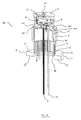
- FIG. 1 provides a perspective front view of an exemplary DSC assembly 50 that can be readily coupled to a variety of cooling devices.
- DSC assembly 50 includes basic components furnace block assembly 1 and DSC coupling assembly 19.
- DSC coupling assembly 19 of the present invention permits coupling of furnace block assembly 1 to a variety of cooling devices for effective, efficient measurements in a wide range of temperature regimes. It will be appreciated by those of skill in the art that furnace block assembly 1 is exemplary and illustrative only, and that different furnace block designs could be coupled to DSC coupling assembly 19.
- DSC assembly 50 As depicted in Figure 1 , the basic components of DSC assembly 50 are furnace block assembly 1, DSC coupling assembly 19 comprising thermal resistor 9 and cooling flange 10. Figure 1 also shows leads 14, 15, 16 and purge gas tube 17. DSC assembly 50 of Figure 1 can be coupled to a selected cooling device at cooling flange 10.
- Furnace block assembly 1 encloses DSC sensor 22 (shown in figure 2 ) that receives the sample and the reference material to be measured and provides the thermal stimulation during the course of a measurement.
- Thermal resistor 9 provides a conduit for heat conduction from furnace block assembly 1 to cooling flange 10 and then to the cooling device (not shown).
- Cooling flange 10 receives the heat transmitted from furnace block 1 and transmits it to the cooling device, which is coupled to surface 12 of cooling flange 10.
- Cooling flange 10 also provides a reliable, standard physical interface between DSC assembly 50 and replaceable cooling devices.
- Furnace block assembly 1 comprises measurement chamber 2 and furnace heater 3.
- Measurement chamber 2 which holds the sample and the reference material, includes generally cylindrical main body 7 topped by outer cover 4 that has handle 5.
- Measurement chamber 2 encloses the sample and the reference material.
- furnace heater 3 heats measurement chamber 2 to heat the sample and the reference material (if a reference material is used).
- furnace heater 3 heats measurement chamber 2 to heat the sample and the reference material.
- cylindrical furnace heater 3 includes a series of electrically resistive windings (not shown) around its circumference, which are then secured with cement 6.
- Cement 6 can be selected depending on the operating range of the device. For example, for operating at high temperatures, ceramic cements are preferable. When current is applied, these windings will cause furnace heater 3 to provide heat to measurement chamber 2.
- furnace block assembly 1 is an exemplary furnace block assembly intended to provide but one example of how a DSC coupling assembly 19 could integrate a given furnace block assembly with a selected cooling device.
- the artisan of ordinary skill will readily appreciate that other furnace block assemblies could be employed as long as they maintain the characteristic of providing well defined and reproducible heat exchange between the furnace block assembly (or its components) and the cooling device.
- FIG 2 provides a cutaway illustration of the assembly of Figure 1 .
- Inner cover 32 is removed to insert the sample and the reference material.
- Outer cover 4 further isolates inner cover 32 from the external environment.
- the sample and the reference material are located in pans placed upon DSC sensor 22 at locations 23 and 24, which include temperature detectors for measuring differential temperature that may be converted into heat flow.
- Temperature detectors may be thermocouples. Specific examples of thermocouples include Type E chromel-constantan thermocouples. Other temperature detectors may include platinum resistance thermometers.
- the windings are applied in a spool-like manner to thin wall cylindrical section 25 between upper flange 27 and lower flange 26.
- This mechanism for heating is exemplary only and other mechanisms for heating furnace heater 3 could be employed.
- heating strips or other types of heating elements could be employed instead of windings.
- furnace block assembly 1 is preferably an integral body made of a high thermal conductivity material that is resistant to corrosion, such as silver.
- the integral body and high thermal conductivity provide a uniform temperature distribution across measurement chamber 2. Temperature gradients and other nonuniformities may be harmful to accurate and precise measurements. For example, they may result in the sample and the reference material being exposed to different temperatures.
- the use of an integral body for furnace block assembly 1 is exemplary only. Two-piece or other constructions could be employed so long as the desired thermal conductivity/uniformity is achieved and the overall furnace block assembly can be reliably coupled to DSC coupling assembly 19.
- Thermal resistor 9 provides a well defined thermal path between furnace heater 3 and the cooling flange 10. During high temperature above-ambient testing, thermal resistor 9 provides a pathway to the heat sink via cooling flange 10. Yet it does not place such a cooling load on furnace heater 3 such that it cannot reach desired maximum temperatures or desired heating rates. Additionally, thermal resistor 9 is designed to withstand the mechanical stresses associated with the differential expansion and contraction that furnace heater 3 and cooling flange 10 will undergo during operation. Accordingly, the materials and structure are selected so that thermal resistor 9 can withstand these stresses without breakage or permanent deformation.
- thermal resistor 9 is designed to have a thermal resistance in the range 1 to 5 °C/W (degrees Celsius per Watt), preferably about 3 °C/W.
- This value permits DSC coupling assembly 19 to be used with a variety of cooling devices to permit a broad temperature profile range capability in a generally efficient manner.
- this value is sufficiently high that exemplary furnace block assembly 1 can be adequately cooled using a finned cooling device during above-ambient operations.
- thermal resistor 9 should also demonstrate mechanical strength and resilience (flexibility), as well as resistance to oxidation and corrosion. These characteristics extend the operational life of thermal resistor 9.
- thermal resistor 9 may be constructed using a nickel alloy, such as nickel alloy 201, which provides an acceptable combination of thermal conductivity, mechanical strength, and resistance to corrosion and oxidation.
- nickel alloy 201 which provides an acceptable combination of thermal conductivity, mechanical strength, and resistance to corrosion and oxidation.
- Other metals and/or metal alloys suitable to the desired temperature range and having appropriate mechanical properties may also be used.
- thermal resistor 9 in one embodiment it comprises a series of thin members 31 disposed between the bottom of furnace heater 3 and top of cooling flange 10.
- the length and thickness of thin members 31 are chosen so that the strains induced by the differential expansion are within the elastic operating range of the material. This makes it less likely that the thin members 31 will be deformed over time through the accumulation of plastic strain.
- thin members 31 comprise a series of cylindrical rods having a diameter in the range of about 25 to 75 one-thousandths of an inch (0.025 of an inch to 0.075 of an inch), preferably about 50 one-thousandths of an inch in (0.050) diameter.
- the cylindrical rods are in the range of 0.4-1.0 inch in length, preferably about 0.7 inch.
- Thin members 31 could alternatively have a rectangular cross-section, triangular cross-section, hexagonal cross-section, or other cross-sectional shape. Generally, manufacturability/cost considerations militate in favor of using the generally circular cross-section.
- the lengthwise axes of thin members 31 are substantially perpendicular to the top 12 of cooling flange 10 and bottom of furnace heater 3.
- the upper and lower ends of thin members 31 are coupled to furnace heater 3 and cooling flange 10, respectively, through brazing. Other techniques for attachment could be used.
- the series of thin members 31 comprising thermal resistor 9 are equally spaced to preserve temperature uniformity along an inner circumference or periphery on the top surface 12 of cooling flange 10.
- Other spacing patterns such as a rectangular, triangular, hexagonal, etc.
- One benefit of the roughly equidistant spacing is that heat transmitted through thermal resistor 9 is conducted to cooling flange 10 in a relatively uniform manner. This relatively uniform transfer of heat reduces the likelihood of thermal gradients and nonuniformities in measurement chamber 2.
- the generally cylindrical array defined by thin members 31 is sufficiently flexible to absorb differential expansion strains during measurement operations, and is sufficiently resilient to return to its nominal shape afterwards.
- Thin members 31 could be alternatively arranged so as to define a generally rectangular, triangular, hexagonal or other array adequate to absorb operational stresses without permanent deformation.
- FIG 2 provides a cutaway view of thermal resistor 9 comprised of thin members 31.
- thermal resistor 9 comprised of thin members 31.
- a contiguous thin-walled cylinder may define an inner circumference on the top surface 12 of cooling flange 10 similar to that defined by the array of thin members illustrated in Figures 1 and 2 .
- the wall thickness of such a thin-walled cylinder would be in the range of about 5 to 50 one-thousandths of an inch (0.005 to 0.05 inch) for a cylinder having a diameter of 1 to 1.5 inches.
- the height of such a thin-walled cylinder would be at the lower end of the 0.4 to 1.0 inch range.
- an array of individual members is preferred over a thin-walled cylinder because the former provides a more acceptable combination of stress absorption and resilience.
- cooling flange 10 physically couples thermal resistor 9 to the cooling device. Because the design of the DSC assembly 50 of Figure 1 supports a broad range of applications (high temperature profiles, low temperature profiles, fast heating and cooling rates, etc.), the operator can attach a variety of cooling devices to cooling flange 10 based on the requirements of the application.
- a nonexhaustive list of cooling devices that could be connected to cooling flange 10 includes: cooling fins (natural or forced convection), liquid cooled heat exchangers, gas cooled heat exchangers, and change of phase liquid-gas heat exchangers (open loop or closed loop). Other types of cooling devices could also be used.
- cooling flange 10 is a generally cylindrical disk having a top surface 12, a bottom surface 13, and a lateral surface 11 defining an outer circumference. Cooling flange 10 is adapted to interface with a cooling device having an opening at one end which is generally reciprocal to top surface 12 and lateral surface 11. While not illustrated by Figure 1 , such cooling devices will typically have a cylindrical shape with an opening that allows them to be slid over furnace block assembly 1. The opening then reciprocally mates with lateral surface 11 (to hold the cooling device in place) and with top surface 12 (for heat transfer and to provide vertical support). Accordingly, the heat transfer from cooling flange 10 to the cooling device will be fairly uniform with the dominant heat transfer mechanism being from top surface 12 (rather from lateral surface 11) to the cooling device.
- cooling flange 10 there are several other details of cooling flange 10 that may vary according to the particular embodiment without departing from the spirit and scope of the invention.
- support holes 8 in cooling flange 10 for holding supporting leg members (not shown) supporting an entire structure.
- These supporting leg members which extend down to a base support, are preferably tubes or rods with a low thermal conductivity, such as stainless steel. This low thermal conductivity of the leg members minimizes any heat flow through the legs to cooling flange 10.
- Figure 1 also depicts mounting hole 18 for attaching a temperature detector to surface 13 to monitor the temperature of cooling flange 10.
- Cooling flange 10 is designed to thermally couple furnace heater 3 (a heat producer) to the cooling device (a heat sink). As such, cooling flange 10 should have a high thermal conductivity and should be resistant to moderately high and low temperatures. It should also be resistant to oxidation or corrosion that might impair its heat exchange function. It has been found that cooling flange 10 can be constructed of a nickel alloy, such as nickel alloy 201, which provides a good compromise between the aforementioned considerations. Exemplary dimensions for cooling flange 10 include a diameter along top surface 12 of about 2.37 inches and a width of about 0.375 inches along lateral surface 11.
- FIG. 2 A cutaway view of cooling flange 10 is provided in Figure 2 .
- bottom surface 13 has been countersunk to a depth 29.
- the diameter of the countersink hole in bottom surface 13 is somewhat larger than the hole in the top surface 12 around which thin members 31 are arranged. Accordingly, distance 28 is somewhat smaller than distance 30. As shown in Figure 3 , this permits the lower end of thin members 31 to terminate at the top of depth 29.
- the difference in the diameters of the hole in bottom surface 13 and that in top surface 12 is greater than the diameter of thin members 31.
- leads 14, 15, 16 project from the bottom of that assembly.
- lead 14 is the heater lead for providing power to the heater coils of furnace heater 3.
- Lead 15 connects to an overtemperature sensor located in furnace block assembly 1.
- Lead 16 connects to the thermocouple sensors in measurement chamber 2.
- purge gas tube 17 discharges gas into measurement chamber 20.
- FIG 4 provides a functional block diagram illustration of the operational environment of the present invention.
- DSC assembly 40 is similar to that previously described as DSC assembly 50 in Figure 1 , which is coupled to replaceable cooling device 46 that is suitable for the desired application.
- cooling device 46 might comprise a cooling fin type device, liquid cooled heat exchanger, gas cooled heat exchanger, change of phase heat exchanger, and so on.
- heater power control 47 is provided for heater power
- cooler controller 48 enables cooling device 46.
- there may be no control requirements for replaceable cooling device 46 if cooling device 46 is, for example, a cooling finned natural convection device.
- Control processing module 44 includes the control processing circuitry for ensuring that DSC assembly 40 follows the temperature profile input. Control processing module 44 receives measurements of heat/temperature from the signal amplifier and analog to digital conversion module 49 and adjusts heater power control 47 to follow the programmed temperature profile. In theory, control processing module 44 could request that the cooler controller 48 change the cooling load as part of the temperature control process. However, it is been found that it is generally more efficient for heater power to be the sole output control parameter and, accordingly, cooler controller 48 is preferably not adjusted by control processing module 44.
- Temperature sensor outputs from DSC assembly 40 are amplified and converted into a digital format by signal amplification and analog to digital conversion module 49 and are read by control processing module 44 (which may further process the measurements and format them for output as graphs or the like on a computer video screen, a plotter, or a hard copy printer).
- Block diagram of Figure 4 is a functional representation and that certain functions could be combined or further subdivided.
- control processing module 44, heater power control 47 and signal amplification and analog to digital conversion module 49 could easily be performed on a single programmable or special application computer.
- the distributed thermal resistor provides uniform and reproducible cooling for accurate, precise measurements.
- the physical configuration of the thermal resistor is robust, tolerating simultaneous expansion of the heater and contraction of the cooling flange.
- the thermal resistor is resilient and returns to its nominal shape after such mechanical stresses.
- the location of the thermal heater between the measurement chamber and the cooling device in the present invention is a further advantage. In this orientation, heat flowing towards the heat sink (cooling flange/cooling device) avoids the measurement chamber and thus the problem of temperature nonuniformity is greatly mitigated.
Landscapes
- Chemical & Material Sciences (AREA)
- Engineering & Computer Science (AREA)
- Chemical Kinetics & Catalysis (AREA)
- Combustion & Propulsion (AREA)
- Physics & Mathematics (AREA)
- Health & Medical Sciences (AREA)
- Life Sciences & Earth Sciences (AREA)
- Analytical Chemistry (AREA)
- Biochemistry (AREA)
- General Health & Medical Sciences (AREA)
- General Physics & Mathematics (AREA)
- Immunology (AREA)
- Pathology (AREA)
- Investigating Or Analyzing Materials Using Thermal Means (AREA)
Claims (17)
- Differentialkalorimeter (50), umfassend:eine Messkammer (2) zur Aufnahme einer Probe;ein operativ mit der Messkammer (2) verbundenes Ofenheizgerät (3) zum Erhitzen der Messkammer (2);eine Kupplungsbaugruppe (19), umfassendeinen Kühlflansch (10), der als Wärmesenke in Bezug auf die Messkammer (2) fungiert; und einen Heizwiderstand (9) mit einer Reihe von Längselementen (31), wobei der Heizwiderstand (9) zwischen dem Ofenheizgerät (3) und dem Kühlflansch (10) angeordnet ist, um einen Wärmeübertragungsweg vom Ofenheizgerät (3) zum Kühlflansch (10) bereitzustellen;und wobei der Kühlflansch (10) eine generell zylindrische Scheibe mit einer generell flachen oberen Oberfläche (12), einer unteren Oberfläche (13) und einer seitlichen Oberfläche (11) zur Definition eines äußeren Umfangs umfasst, dadurch gekennzeichnet, dass die Reihe von Längselementen (31) in einem im Wesentlichen senkrechten Winkel zu besagter oberer Oberfläche (12) angeordnet sind und ein generell kreisförmiges Muster entlang einer inneren Peripherie des Kühlflansches (10) definieren.
- Kalorimeter nach Anspruch 1, wobei die Längselemente (31) generell zylindrische Stäbe sind.
- Kalorimeter nach Anspruch 1, wobei die Längselemente (31) Stäbe mit einem Querschnitt umfassen, der eine Form aus rechteckig, sechseckig und dreieckig aufweist.
- Kalorimeter nach Anspruch 1, wobei die Längselemente (31) einen Durchmesser im Bereich von etwa 0,025 bis etwa 0,075 Zoll (0,064 bis etwa 0,191 cm) aufweisen.
- Kalorimeter nach Anspruch 1, wobei die Längselemente (31) einen Durchmesser von etwa 0,05 Zoll (0,127 cm) aufweisen.
- Kalorimeter nach Anspruch 1, wobei die Längselemente (31) eine Länge im Bereich von etwa 0,4 bis etwa 1 Zoll (1,0 bis etwa 2,5 cm) aufweisen.
- Kalorimeter nach Anspruch 1, wobei die Längselemente (31) eine Länge von etwa 0,7 Zoll (1,8 cm) aufweisen.
- Kalorimeter nach Anspruch 1, wobei der Heizwiderstand (9) aus einer Nickellegierung besteht.
- Kalorimeter nach Anspruch 1, wobei jedes der Längselemente (31) ein oberes Ende und ein unteres Ende aufweist.
- Kalorimeter nach Anspruch 9, wobei das untere Ende an der generell flachen oberen Oberfläche (12) des Kühlflansches (10) aufhört.
- Kalorimeter nach Anspruch 1, wobei das Ofenheizgerät (3) zwischen der Messkammer (2) und dem Heizwiderstand (9) angeordnet ist.
- Kalorimeter nach Anspruch 1, wobei der Heizwiderstand bei der Rückkehr zu Umgebungsbedingungen wieder eine Sollform annimmt.
- Kalorimeter nach Anspruch 1, wobei der Kühlflansch (10) eine zylindrische Scheibe mit einer oberen Oberfläche (12), einer unteren Oberfläche (13) und einer seitlichen Oberfläche (11) zur Definition eines äußeren Umfangs ist, ferner umfassend Mittel zum Verbinden des Kühlflansches (10) mit einem wählbaren einer Mehrzahl von Kühlmitteln.
- Kalorimeter nach Anspruch 9, wobei die unteren Enden an der oberen Oberfläche (12) der zylindrischen Scheibe angebracht sind, um somit einen inneren Umfang entlang der oberen Oberfläche (12) zu definieren.
- Kalorimeter nach Anspruch 1, wobei die Heizwiderstand (9) ein angrenzender dünnwandiger Zylinder ist.
- Kalorimeter nach Anspruch 15, wobei der dünnwandige Zylinder einen inneren Umfang auf der oberen Oberfläche (12) des Flansches (10) definiert.
- Kalorimeter nach Anspruch 9, wobei die unteren Enden der Längselemente (31) so auf der generell flachen oberen Oberfläche (12) des Kühlflansches (10) beabstandet sind, dass der Abstand zwischen jedem Paar benachbarter Längselemente (31) ungefähr derselbe ist.
Applications Claiming Priority (2)
| Application Number | Priority Date | Filing Date | Title |
|---|---|---|---|
| US09/769,320 US6523998B1 (en) | 2001-01-26 | 2001-01-26 | Thermal analysis assembly with distributed resistance and integral flange for mounting various cooling devices |
| US769320 | 2001-01-26 |
Publications (3)
| Publication Number | Publication Date |
|---|---|
| EP1227317A2 EP1227317A2 (de) | 2002-07-31 |
| EP1227317A3 EP1227317A3 (de) | 2004-02-04 |
| EP1227317B1 true EP1227317B1 (de) | 2014-09-03 |
Family
ID=25085106
Family Applications (1)
| Application Number | Title | Priority Date | Filing Date |
|---|---|---|---|
| EP02001504.6A Expired - Lifetime EP1227317B1 (de) | 2001-01-26 | 2002-01-22 | Thermisches Analysegerät mit verteiltem Widerstand und integriertem Flansch zur Befestigung von verschiedenen Kühlvorrichtungen |
Country Status (3)
| Country | Link |
|---|---|
| US (1) | US6523998B1 (de) |
| EP (1) | EP1227317B1 (de) |
| JP (1) | JP4181776B2 (de) |
Families Citing this family (16)
| Publication number | Priority date | Publication date | Assignee | Title |
|---|---|---|---|---|
| AU2002325030A1 (en) * | 2001-09-18 | 2003-04-01 | Energetic Geonomics Corporation | A high throughput energy array |
| JP4116526B2 (ja) * | 2003-11-18 | 2008-07-09 | エスアイアイ・ナノテクノロジー株式会社 | 第二のヒーターを備えた示差走査熱量計 |
| US7125163B2 (en) * | 2003-11-24 | 2006-10-24 | The Boeing Company | Simple high accuracy high energy calorimeter |
| US7371006B2 (en) * | 2004-02-10 | 2008-05-13 | Perkinelmer Las, Inc. | Differential scanning calorimeter (DSC) with temperature controlled furnace |
| US7481575B2 (en) * | 2005-05-05 | 2009-01-27 | Leco Corporation | Calorimeter |
| JP4868305B2 (ja) * | 2006-01-27 | 2012-02-01 | エスアイアイ・ナノテクノロジー株式会社 | 示差走査熱量計 |
| DE112008001385B4 (de) | 2007-06-06 | 2014-10-09 | Waters Technologies Corp. | Mit Infrarot beheiztes dynamisches Differenzkalorimeter |
| FR2917163B1 (fr) * | 2007-06-06 | 2015-10-23 | Waters Investments Ltd | Calorimetre a balayage differentiel a chauffage infrarouge |
| US8087821B2 (en) * | 2007-06-06 | 2012-01-03 | Waters Technologies Corporation | Infrared heated differential scanning calorimeter |
| US8418480B2 (en) * | 2008-12-18 | 2013-04-16 | Waters Technologies Corporation | Cooling system using positive displacement cryogenic liquid pump |
| JP5283535B2 (ja) * | 2009-02-20 | 2013-09-04 | 株式会社日立ハイテクサイエンス | 示差走査熱量計 |
| EP2325628B1 (de) * | 2009-11-23 | 2013-06-26 | Mettler-Toledo AG | Thermoanalysevorrichtung |
| CN103542946B (zh) * | 2012-07-12 | 2016-03-09 | 中国石油天然气股份有限公司 | 一种温度检测组件 |
| JP5551811B2 (ja) * | 2013-05-24 | 2014-07-16 | 株式会社日立ハイテクサイエンス | 示差走査熱量計 |
| JP6841425B2 (ja) * | 2017-05-26 | 2021-03-10 | 株式会社リガク | 熱分析装置 |
| US10755200B2 (en) | 2017-09-22 | 2020-08-25 | International Business Machines Corporation | Automated control of circumferential variability of blast furnace |
Family Cites Families (26)
| Publication number | Priority date | Publication date | Assignee | Title |
|---|---|---|---|---|
| US3339398A (en) | 1964-03-30 | 1967-09-05 | Chevron Res | High sensitivity differential thermal analysis apparatus and method |
| US3456490A (en) | 1967-04-21 | 1969-07-22 | Tracor | Differential thermal analysis |
| GB1259453A (de) | 1968-01-25 | 1972-01-05 | ||
| US3774078A (en) * | 1972-03-29 | 1973-11-20 | Massachusetts Inst Technology | Thermally integrated electronic assembly with tapered heat conductor |
| US3813937A (en) * | 1972-06-16 | 1974-06-04 | J Fletcher | Heat flow calorimeter |
| CH573114A5 (de) | 1974-06-25 | 1976-02-27 | Mettler Instrumente Ag | |
| US4050302A (en) * | 1975-02-10 | 1977-09-27 | Aluminum Company Of America | Thermoelectric heat flow transducer |
| JPH0765974B2 (ja) | 1988-10-26 | 1995-07-19 | セイコー電子工業株式会社 | 熱分析装置の加熱炉部冷却装置 |
| US5224538A (en) * | 1991-11-01 | 1993-07-06 | Jacoby John H | Dimpled heat transfer surface and method of making same |
| US5224775C2 (en) | 1992-03-02 | 2002-04-23 | Ta Instr Inc | Method and apparatus for modulated differential analysis |
| US5711604A (en) * | 1993-12-14 | 1998-01-27 | Seiko Instruments Inc. | Method for measuring the coefficient of heat conductivity of a sample |
| US5509733A (en) * | 1993-12-21 | 1996-04-23 | Ta Instruments, Inc. | Infrared heated differential thermal analyzer |
| US5484204A (en) | 1994-09-21 | 1996-01-16 | Ta Instruments, Inc. | Mechanical cooling system |
| KR0156622B1 (ko) * | 1995-04-27 | 1998-10-15 | 문정환 | 반도체 패키지,리드프레임 및 제조방법 |
| EP0762045B1 (de) * | 1995-09-07 | 2003-12-03 | The Perkin-Elmer Corporation | Wärmedämmung für Flüssiggasbehälter |
| US5876118A (en) | 1995-12-08 | 1999-03-02 | The Perkin-Elmer Corporation | Calorimeter having rapid cooling of a heating vessel therein |
| JPH1054813A (ja) | 1996-08-08 | 1998-02-24 | Shimadzu Corp | 示差走査熱量測定装置 |
| JPH10132770A (ja) | 1996-10-31 | 1998-05-22 | Shimadzu Corp | 熱分析装置 |
| JPH10246577A (ja) | 1997-03-03 | 1998-09-14 | Rigaku Corp | 加熱炉の冷却方法及び装置 |
| US6694731B2 (en) * | 1997-07-15 | 2004-02-24 | Deka Products Limited Partnership | Stirling engine thermal system improvements |
| JP2000174182A (ja) * | 1998-12-08 | 2000-06-23 | Nec Eng Ltd | ヒートシンク |
| US6238613B1 (en) * | 1999-07-14 | 2001-05-29 | Stratasys, Inc. | Apparatus and method for thermoplastic extrusion |
| US6308518B1 (en) * | 1999-09-28 | 2001-10-30 | Rick C. Hunter | Thermal barrier enclosure system |
| US6428203B1 (en) * | 2000-03-23 | 2002-08-06 | Ta Instruments, Inc. | Power compensation differential scanning calorimeter |
| WO2002006803A1 (en) * | 2000-07-13 | 2002-01-24 | Igc-Apd Cryogenics, Inc. | Cooling system for thermal analysis |
| US20020163781A1 (en) * | 2001-05-01 | 2002-11-07 | Ericsson Inc. | Integrated cooling of a printed circuit board structure |
-
2001
- 2001-01-26 US US09/769,320 patent/US6523998B1/en not_active Expired - Lifetime
-
2002
- 2002-01-22 EP EP02001504.6A patent/EP1227317B1/de not_active Expired - Lifetime
- 2002-01-28 JP JP2002017997A patent/JP4181776B2/ja not_active Expired - Lifetime
Also Published As
| Publication number | Publication date |
|---|---|
| EP1227317A3 (de) | 2004-02-04 |
| EP1227317A2 (de) | 2002-07-31 |
| JP4181776B2 (ja) | 2008-11-19 |
| US6523998B1 (en) | 2003-02-25 |
| JP2002310965A (ja) | 2002-10-23 |
Similar Documents
| Publication | Publication Date | Title |
|---|---|---|
| EP1227317B1 (de) | Thermisches Analysegerät mit verteiltem Widerstand und integriertem Flansch zur Befestigung von verschiedenen Kühlvorrichtungen | |
| Childs | Practical temperature measurement | |
| JP3936847B2 (ja) | 変調差分走査熱量計 | |
| EP2290356B1 (de) | Dynamisches Differenzkalorimeter mit temperaturgesteuertem Ofen | |
| US8496374B2 (en) | Differential scanning calorimeter | |
| US20090092169A1 (en) | Device, Method and Vessel Assembly for the Measurement of Heat Flow at Least One Sample | |
| EP2988119B1 (de) | Apparat und methode zur differentiellen thermogravimetrischen analyse mit je einer eigenen wärmesenke für probenhalter und referenzmaterialhalter | |
| US20040107986A1 (en) | High throughput microcalorimeter systems and methods | |
| CN110785641B (zh) | 量热计 | |
| UA96386C2 (uk) | Електричний нагрівальний елемент | |
| Merlone et al. | Gas-controlled heat pipes in metrology: More than 30 years of technical and scientific progresses | |
| US8746967B2 (en) | Large array differential scanning calorimeter, DSC measuring unit | |
| WO1994006000A1 (en) | Differential scanning calorimeter | |
| Platunov | Instruments for measuring thermal conductivity, thermal diffusivity, and specific heat under monotonic heating | |
| CN207964129U (zh) | 一种温度校准的装置 | |
| US3336790A (en) | Thermographic calorimetry device | |
| Kaisersberger et al. | A heat flux DSC for enthalpy and specific heat determinations to 1700 K | |
| EP3798626B1 (de) | Vorrichtung zur thermischen analyse, probenhalteranordnung und verfahren zur thermischen analyse | |
| Lovas et al. | Meeting RTP temperature accuracy requirements: measurement and calibrations at NIST | |
| Patt et al. | Thermal time constants in differential scanning calorimetry | |
| JPS62231148A (ja) | 熱分析装置 | |
| CN108562378A (zh) | 一种温度校准的装置 | |
| SU1052960A1 (ru) | Устройство дл термогравиметрического анализа | |
| SU786543A1 (ru) | Нагреватель термолюминесцентных детекторов | |
| Hill | Realizing the ITS-90 below 4.2 K at the National Research Council of Canada |
Legal Events
| Date | Code | Title | Description |
|---|---|---|---|
| PUAI | Public reference made under article 153(3) epc to a published international application that has entered the european phase |
Free format text: ORIGINAL CODE: 0009012 |
|
| AK | Designated contracting states |
Kind code of ref document: A2 Designated state(s): AT BE CH CY DE DK ES FI FR GB GR IE IT LI LU MC NL PT SE TR |
|
| AX | Request for extension of the european patent |
Free format text: AL;LT;LV;MK;RO;SI |
|
| PUAL | Search report despatched |
Free format text: ORIGINAL CODE: 0009013 |
|
| AK | Designated contracting states |
Kind code of ref document: A3 Designated state(s): AT BE CH CY DE DK ES FI FR GB GR IE IT LI LU MC NL PT SE TR |
|
| AX | Request for extension of the european patent |
Extension state: AL LT LV MK RO SI |
|
| 17P | Request for examination filed |
Effective date: 20040407 |
|
| AKX | Designation fees paid |
Designated state(s): BE CH DE FR GB LI NL |
|
| 17Q | First examination report despatched |
Effective date: 20071009 |
|
| GRAP | Despatch of communication of intention to grant a patent |
Free format text: ORIGINAL CODE: EPIDOSNIGR1 |
|
| INTG | Intention to grant announced |
Effective date: 20140401 |
|
| GRAP | Despatch of communication of intention to grant a patent |
Free format text: ORIGINAL CODE: EPIDOSNIGR1 |
|
| INTG | Intention to grant announced |
Effective date: 20140617 |
|
| GRAS | Grant fee paid |
Free format text: ORIGINAL CODE: EPIDOSNIGR3 |
|
| GRAA | (expected) grant |
Free format text: ORIGINAL CODE: 0009210 |
|
| AK | Designated contracting states |
Kind code of ref document: B1 Designated state(s): BE CH DE FR GB LI NL |
|
| REG | Reference to a national code |
Ref country code: GB Ref legal event code: FG4D |
|
| REG | Reference to a national code |
Ref country code: CH Ref legal event code: EP |
|
| REG | Reference to a national code |
Ref country code: DE Ref legal event code: R096 Ref document number: 60246591 Country of ref document: DE Effective date: 20141009 |
|
| REG | Reference to a national code |
Ref country code: NL Ref legal event code: VDEP Effective date: 20140903 |
|
| PG25 | Lapsed in a contracting state [announced via postgrant information from national office to epo] |
Ref country code: NL Free format text: LAPSE BECAUSE OF FAILURE TO SUBMIT A TRANSLATION OF THE DESCRIPTION OR TO PAY THE FEE WITHIN THE PRESCRIBED TIME-LIMIT Effective date: 20140903 |
|
| REG | Reference to a national code |
Ref country code: DE Ref legal event code: R097 Ref document number: 60246591 Country of ref document: DE |
|
| PG25 | Lapsed in a contracting state [announced via postgrant information from national office to epo] |
Ref country code: BE Free format text: LAPSE BECAUSE OF NON-PAYMENT OF DUE FEES Effective date: 20150131 |
|
| PLBE | No opposition filed within time limit |
Free format text: ORIGINAL CODE: 0009261 |
|
| STAA | Information on the status of an ep patent application or granted ep patent |
Free format text: STATUS: NO OPPOSITION FILED WITHIN TIME LIMIT |
|
| REG | Reference to a national code |
Ref country code: DE Ref legal event code: R119 Ref document number: 60246591 Country of ref document: DE |
|
| 26N | No opposition filed |
Effective date: 20150604 |
|
| REG | Reference to a national code |
Ref country code: CH Ref legal event code: PL |
|
| PG25 | Lapsed in a contracting state [announced via postgrant information from national office to epo] |
Ref country code: LI Free format text: LAPSE BECAUSE OF NON-PAYMENT OF DUE FEES Effective date: 20150131 Ref country code: DE Free format text: LAPSE BECAUSE OF NON-PAYMENT OF DUE FEES Effective date: 20150801 Ref country code: CH Free format text: LAPSE BECAUSE OF NON-PAYMENT OF DUE FEES Effective date: 20150131 |
|
| REG | Reference to a national code |
Ref country code: FR Ref legal event code: ST Effective date: 20150930 |
|
| PG25 | Lapsed in a contracting state [announced via postgrant information from national office to epo] |
Ref country code: FR Free format text: LAPSE BECAUSE OF NON-PAYMENT OF DUE FEES Effective date: 20150202 |
|
| PG25 | Lapsed in a contracting state [announced via postgrant information from national office to epo] |
Ref country code: BE Free format text: LAPSE BECAUSE OF FAILURE TO SUBMIT A TRANSLATION OF THE DESCRIPTION OR TO PAY THE FEE WITHIN THE PRESCRIBED TIME-LIMIT Effective date: 20140903 |
|
| PGFP | Annual fee paid to national office [announced via postgrant information from national office to epo] |
Ref country code: GB Payment date: 20201218 Year of fee payment: 20 |
|
| REG | Reference to a national code |
Ref country code: GB Ref legal event code: PE20 Expiry date: 20220121 |
|
| PG25 | Lapsed in a contracting state [announced via postgrant information from national office to epo] |
Ref country code: GB Free format text: LAPSE BECAUSE OF EXPIRATION OF PROTECTION Effective date: 20220121 |