EP1226772A2 - Vorrichtung zur Aufbewahrung von Gegenständen - Google Patents
Vorrichtung zur Aufbewahrung von Gegenständen Download PDFInfo
- Publication number
- EP1226772A2 EP1226772A2 EP01126338A EP01126338A EP1226772A2 EP 1226772 A2 EP1226772 A2 EP 1226772A2 EP 01126338 A EP01126338 A EP 01126338A EP 01126338 A EP01126338 A EP 01126338A EP 1226772 A2 EP1226772 A2 EP 1226772A2
- Authority
- EP
- European Patent Office
- Prior art keywords
- frame
- storing objects
- objects according
- handle
- container
- Prior art date
- Legal status (The legal status is an assumption and is not a legal conclusion. Google has not performed a legal analysis and makes no representation as to the accuracy of the status listed.)
- Withdrawn
Links
Images



Classifications
-
- A—HUMAN NECESSITIES
- A45—HAND OR TRAVELLING ARTICLES
- A45F—TRAVELLING OR CAMP EQUIPMENT: SACKS OR PACKS CARRIED ON THE BODY
- A45F5/00—Holders or carriers for hand articles; Holders or carriers for use while travelling or camping
- A45F5/10—Handles for carrying purposes
- A45F5/102—Handles for carrying purposes with means, e.g. a hook, receiving a carrying element of the hand article to be carried
Definitions
- the present invention relates to a device for Storage of items including a rack as well at least one detachably attachable to this frame Container.
- a device is, for example, from the prior art of the genus mentioned at the beginning, the includes various containers that can be detached from a frame can be fastened so that you can sort various objects in insert the individual containers and separate them there can keep.
- the device is also designed that you can use two or more containers as needed can use because it is modular.
- a device of this type is considered Laundry sorter used.
- the known device according to DE 196 24 985.6 A1 is equipped with wheels and thus overall mobile.
- the individual containers of the device are accessible via hinged flaps.
- the object of the present invention is a Device for storing objects of the beginning to create the genus mentioned, which is overall portable is trained and is particularly simple.
- the device according to the invention is not a device Driving from one place to another but spent through Wear. For this is on the frame in the upper end area Handle attached.
- the device according to the invention is very simple built and designed so that if you only have one Wants to transport containers separately, this very easy can be released from the device by lifting upwards.
- the containers of the device according to the invention preferably designed to be very light can be opened when the containers on the rack are located. You can, for example, each of the containers Provide device with rods, each on the upper end areas of the container. Hanging the Container on the frame can then be done by put both rods into the frame's suspension device mounts. Opening the container is also very easy easily possible, for example, by only a rod, namely the outer one, from the hanging device decreases, with the other rod in the hanger remains and the container is then opened in the upper area is so that objects are thrown or inserted can.
- the containers preferably bags or pouches or boxes or Cardboard boxes or the like. This means it will come basically containers with a flexible outer skin in Consider how this is the case with bags or pouches also containers with a rigid outer skin z. B. boxes.
- the Containers can be made of textile or plastic or Cardboard or leather or other suitable materials consist.
- each container has two rods in its upper one Has end area, so that only the outer rod from the hanger in the manner mentioned Open the container and remove the container altogether by lifting up both rods of that Hanging brackets can be lifted off.
- the Hanging device which is for example a wire bracket
- On the hanging device has the side facing away from the handle then the hanging ends, in which preferably the rods be placed where the container is located.
- the frame of a device according to the invention is preferably also very simply constructed and exists for example, from rods or tubes that are in one hand are bent so that there are parts of the foot on the Stand up. These footboards can be cut into sections of the Pass over, which extend upwards and in the top of which the handle is attached. Farther the foot parts preferably initially extend outwards and then in further sections in the longitudinal direction of the Frame.
- the containers are, for example bag-shaped or bag-like and have preferably a relatively elongated shape. You can the containers should be shaped so that in the closed form seen from the front of the frame from above below the width increases.
- a device according to the invention with two such Containers are preferred.
- the frame so that only one container or more than two containers are hung in it, without leaving the principle of the invention.
- the containers suspended in the hooking device end at a distance from the lower end of the frame and from Underground so that they do not touch the underground and cannot get dirty.
- the frame can be very much just build it up by extending it tubular or rod-shaped sections in one easily deviates from the vertical angle in such a way that both upward extending sections after converge above.
- they can go up extending sections be bent and seamless into the im pass over substantially horizontally curved foot parts.
- Claims 15 to 18 relate to a variant of Device according to the invention, in which instead of a Frame is a holding part, which is on a wall is attachable.
- a Frame is a holding part, which is on a wall is attachable.
- Attachment device can be attached to the holding part, in the form a wire bracket or the like, which is formed exactly like this can be like the hanger on the previous one described variant of the invention.
- this variant can also hang a container or if necessary can be completely removed from the holding part
- Containers can be designed exactly the same way as the container in the previously described variant of Invention with the frame. With this on a wall attachable variant of the invention is usually only one such a container exists and consequently only one Hanging device for this container.
- the container in the upper Area have two horizontal bars so that if only one bar is removed from the suspension device (Wire hanger) the container is opened and when removed the container is removed from both rods.
- the frame is used in this variant of the invention wall-mounted holding part available, which there remains stationary.
- the container can, however, of this Holding part removed and carried.
- a special Another advantage is that the device according to this Variant an addition to the previously described variant of Device with frame forms, and that the container for both variants can be of the same design and therefore also alternatively used for both variants of the device can be.
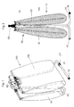
- FIG. 1 The perspective The illustration shows an overall view of an invention Device for storing various objects Art.
- the device is designated a total of 100 and is suitable for storing laundry, for example or other household items, but is not limited to such an application.
- the device comprises a frame 110, which essentially consists of a tube bent several times, the shape of which one can also be seen in Figure 2.
- the tubular frame 110 is bent so that it has two foot parts 111, 112 which run essentially horizontally and the frame on the Support the surface. Connected to the foot parts 111, 112 are vertical pipe sections 113, 114, respectively approximately vertical, d.
- frame 110 a little differently, especially that Form standpipe in two or more parts to thereby to achieve a smaller packaging size.
- the frame 110 then consists of several pipe sections that are together are connected, preferably via pipe connectors Plastic, in which then on both sides in corresponding receptacles the individual pipe sections can be inserted.
- bracket 150, 151st are attachable to the handle 120 by inserting its ends. This can be better seen from the enlarged detailed view Figure 5 recognize. Inserting the ends of the brackets 150, 151 in the handle 120 with reference to Figures 5 and 6 explained in more detail.
- bracket 150 that is in there Perspective view shown detached from the handle 120 is.
- the bracket 150 is where the insertion done in the handle 120, cranked several times.
- the bracket 150 is bent from wire, for example, so that on the handle side result in two sections 152, 153 which are approximately converge horizontally and at a distance from each other ends so that between the two ends of the Bügels a free space 154 remains. Starting from these horizontal sections 152, 153 is the bracket each first cranked upwards by about 90 °, so that in the assembled position approximately vertical sections 155, 156 result.
- the handle 120 is, as can also be seen from FIG. 6, on two slots or holes 122, 123 and on both sides of both holes there are two parallel of bottom guide rails 124, 125.
- the ends of the in Figure 6 wire bracket 150 shown in the slots or holes 122, 123 of the handle 120 inserted that the vertical Sections 159, 162 lie within the handle and follow of the double offset subsequent vertical Sections 155, 156 of the wire bracket 150 between the pair of parallel guide webs 124, 125 down run.
- the connection between Wire bracket 150 and handle 120 ensures that at Lifting the handle 120 and thus the entire device Wire clips 150, 151, which are each shaped the same way cannot disconnect from handle 120.
- Wire brackets are shaped in such a way that there is virtually a support for the rods 140, 142 in four areas of the wire bracket 150 6, 163, 164, 165, 166 are designated. These four sections of the wire bracket all run parallel to each other, the two Areas 163, 164 and the two areas 165, 166, respectively are closer together and between the two areas 164, 165 is a larger distance, where the wire bracket 150 again seen in plan view approximately U-shaped inward toward the handle toward a U-section 167 is bent.
- the wire bracket 150 can also be shaped more simply than this is shown in the exemplary embodiment according to FIG. 6 is to serve the same purpose in principle. For example, a single hanging area is sufficient instead of the hook ends 160, 161, with the wire bracket 150 on could also go through this page, so for example the above in plan view approximately U-shaped inwards curved shape of the wire bracket with the U-section 167 eliminated.
- the wire bracket 150 would then just go through instead of the four areas of the Wire bracket 163, 164, 165, 166 for supporting the bars 140, 142 only two such areas exist that for example, could be outside, as in the drawing 6 the support areas 163, 166.
- the connection of the handle 120 to the upper ends of the tubular sections 113, 114 is below Referring to Figure 7 explained. It's the top there End region of a tubular portion 113 shown and the handle connected to the tubular portion 113 120, which is shown here in section. You can see that the tubular portion 113 on one side a light tongue formed obliquely outwards from the material or nose 170.
- the handle 120 is on both sides each with a circular cylindrical receptacle 171, 172 into which the upper end of the tube section 113, 114 is insertable in each case.
- the pipe section recognizes, for example, approximately on the circumference of the tongue 170 opposite a slot 175 which with corresponding radially protruding parts in the receptacle 171, 172 (not shown) cooperates such that an anti-rotation device each for the pipe section in the Inclusion of the handle results.
- Figures 1 to 5 each show a position in which both bags 130, 131 with their rods 141, 142 and 143, 144, in the bracket 150, 151 are suspended and in the both bags 130, 131 are closed. Opening one of the Pouch is now very easy to do by having the rod 142 and 143, respectively, from the outside curved ends 160 (see FIG. 5), 161 hangs. This opens the bag, the bag but remains on the frame because the other is inside horizontal bar, for example 141 for the right bag in Figure 5 remains on the bracket 150.
- the two rods 141, 142 are each of the two bags each with the material of the bag 130, 131 connected, for example by the rods 141, 142 in sewn, appropriately dimensioned shots in the upper End portion of the fabric of the bag are inserted.
- Both bags 130, 131 can therefore be used separately open if necessary to insert or remove the items to be stored and both bags 130, 131 can one also separately from the frame 110 of the device Lose 100. At the same time it is possible to touch it the handle 120, the entire device 100 with the bags 130, 131 or possibly with only one bag or without Transport bags to another place. Through the Foot parts 111, 112 has the frame of the device with the Bags secure stand.
- Figure 8 shows a perspective view of an alternative Variant of the invention, in which the frame 110 of the Device is slightly different.
- the frame 110 here also vertical sections 113, 114, which extend upwards, but not exactly are vertical, but take an angle with each other and converge towards the handle 120 and on the handle z. B. are attached by inserting the pipe ends.
- the upper area Variant of Figure 8 is not significantly different from that previously described variant.
- the foot parts 111, 112 the frame is slightly different. In this case these each extend in the transverse direction, based on the main direction of expansion of the two containers 130, 131, which are not shown in Figure 8, so that the frame 110 can recognize better.
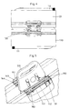
- Figures 9 and 10 show another variant of a Device according to the invention for storing Items made by the manufacturer as an alternative and on the other hand also as a supplement to a device can be offered as previously with reference to the Figures 1 to 7 has been explained.
- the device according to Figure 9 does not have a frame on the floor is set up, but a holding part 10, which a in Principle can be shield-like wall mounting part, which can be attached to a wall, e.g. B. by screwing or similar.
- a holding part 10 which a in Principle can be shield-like wall mounting part, which can be attached to a wall, e.g. B. by screwing or similar.
- How to compare Figures 9 and 1 can see the same container in both cases be used, d. i.e., bag-like or pocket-shaped Container.
- the container is designated 30 in FIG.
- the hanging device 50 for the container 30 in the Principle to be a wire-shaped bracket that is similar in design is like the wire bracket 150 described above, which in the Variant according to Figures 5 and 6 as a hanging device served for the containers 130, 131.
- the Variant according to FIG. 9 only such a hanging device 50 available for only one container 30.
- the as Hanging device 50 serving wire bracket can in Principle be bent exactly as in the previous one described variant, so that the suspension device like can be seen better from the detailed view according to FIG. 10 can, bent in the area facing away from the holding part 10 is such that hanging ends or a hanging area 60 results.
- This hanging device 50 can be held in the holding part 10 are inserted and have insertion ends 59, 62, similar to the variant described above. this has the advantage that the hanging device 50, which in the Variant with the frame according to FIGS. 1 and 5 is used, also for the variant of the device that can be hung on the wall 9 can be used.
- the container 30 can also be designed as in the previously described embodiments, the two containers 130, 131, so that the container 30 as shown in FIG. 9 can recognize two rods 41, 42 in the upper region, each by placing it on the hanging device 150 allow hanging of the container. This also happens Opening the container 30 in the same way that only the respective front (outer) rod 42 from the Hanging device 50 decreases.
Landscapes
- Auxiliary Apparatuses For Manual Packaging Operations (AREA)
- Purses, Travelling Bags, Baskets, Or Suitcases (AREA)
- Supplying Of Containers To The Packaging Station (AREA)
- Packaging Frangible Articles (AREA)
- Packaging Of Annular Or Rod-Shaped Articles, Wearing Apparel, Cassettes, Or The Like (AREA)
- Supports Or Holders For Household Use (AREA)
Abstract
Description
- Fig. 1
- eine perspektivische Gesamtansicht einer erfindungsgemäßen Vorrichtung zum Aufbewahren von Gegenständen;
- Fig. 2
- eine Seitenansicht der in Figur 1 dargestellten Vorrichtung von der Stirnseite her gesehen;
- Fig. 3
- eine weitere Ansicht der erfindungsgemäßen Vorrichtung in einer Blickrichtung 90° zu der Blickrichtung von Figur 2 gesehen;
- Fig. 4
- eine Draufsicht auf die erfindungsgemäße Vorrichtung;
- Fig. 5
- eine vergrößerte Detailansicht im oberen Bereich des Griffs der Vorrichtung;
- Fig. 6
- eine perspektivische Ansicht des Griffs und der an diesem zu befestigenden Bügel separat;
- Fig. 7
- eine Ansicht zur Erläuterung der Verbindung zwischen dem oberen Endbereich des Gestells und dem Griff.
- Fig. 8
- eine perspektivische Ansicht eines Gestells gemäß einer alternativen Variante der Erfindung;
- Fig. 9
- eine perspektivische Ansicht einer alternativen erfindungsgemäßen Vorrichtung zur Aufbewahrung von Gegenständen, die an der Wand anbringbar ist;
- Fig. 10
- eine vergrößerte perspektivische Detailansicht der alternativen Vorrichtung von Figur 9.
Claims (18)
- Vorrichtung zur Aufbewahrung von Gegenständen, umfassend ein Gestell sowie wenigstens einen an diesem Gestell lösbar befestigbaren Behälter,
dadurch gekennzeichnet, dass das Gestell (110) im oberen Endbereich einen Griff (120) zum Tragen aufweist und beidseitig des Griffs Einhängevorrichtungen (150, 151) vorgesehen sind, in die jeweils ein Behälter (130, 131) einhängbar ist, wobei die Behälter durch Anheben nach oben hin von der Einhängevorrichtung abnehmbar sind. - Vorrichtung zur Aufbewahrung von Gegenständen nach Anspruch 1, dadurch gekennzeichnet, dass die Behälter die Form von Taschen (130, 131), Beuteln, Kästen oder Kartons haben.
- Vorrichtung zur Aufbewahrung von Gegenständen nach Anspruch 1 oder 2, dadurch gekennzeichnet, dass die Einhängevorrichtungen (150, 151) jeweils Bügel aus Draht oder dergleichen sind, die gegenüberliegend jeweils beiderseits des Griffs (120) an diesem anbringbar sind.
- Vorrichtung zur Aufbewahrung von Gegenständen nach einem der Ansprüche 1 bis 3, dadurch gekennzeichnet, dass die Behälter (130, 131) in ihren oberen Endbereichen jeweils Stangen (141, 142; 143, 144) aufweisen, die jeweils durch Auflegen auf die Einhängevorrichtungen (150, 151) ein Einhängen der Behälter (130, 131) ermöglichen.
- Vorrichtung zur Aufbewahrung von Gegenständen nach einem der Ansprüche 1 bis 4, dadurch gekennzeichnet, dass jeder Behälter jeweils zwei Stangen (141, 142 bzw. 143, 144) aufweist und bei Abnehmen nur der jeweils äußeren Stange (142, 143) von dem Einhängebügel (150, 151) der Behälter (130, 131) zu öffnen ist.
- Vorrichtung zur Aufbewahrung von Gegenständen nach einem der Ansprüche 1 bis 5, dadurch gekennzeichnet, dass die Einhängevorrichtung (150, 151) Einsteckenden griffseitig aufweist, mittels derer diese am Griff befestigbar ist.
- Vorrichtung zur Aufbewahrung von Gegenständen nach einem der Ansprüche 1 bis 6, dadurch gekennzeichnet, dass die Einhängevorrichtung (150, 151) nach oben aufgebogene Einhängeenden (160, 161) an der dem Griff (120) abgewandten Seite aufweist.
- Vorrichtung zur Aufbewahrung von Gegenständen nach einem der Ansprüche 1 bis 7, dadurch gekennzeichnet, dass das Gestell (110) mindestens teilweise rohrförmig oder stangenförmig ist und der Griff (120) auf die jeweils oberen Enden sich nach oben erstreckender Rohrabschnitte oder Stangenabschnitte (113, 114) des Gestells aufsteckbar und mit diesen kraftschlüssig verbindbar ist.
- Vorrichtung zur Aufbewahrung von Gegenständen nach einem der Ansprüche 1 bis 8, dadurch gekennzeichnet, dass das Gestell (110) rohrförmige oder stangenförmige gebogene Fußteile (111, 112) aufweist, die von der Stirnseite her gesehen sich von den sich nach oben erstreckenden Abschnitten (113, 114) des Gestells sich zunächst nach außen und dann in weiteren Abschnitten in Längsrichtung erstrecken, wobei die jeweiligen Abschnitte des rohroder stangenförmigen Gestells ineinander übergehen.
- Vorrichtung zur Aufbewahrung von Gegenständen nach einem der Ansprüche 1 bis 8, dadurch gekennzeichnet, dass das Gestell sich nach oben erstreckende Abschnitte (113, 114) aufweist und an deren unteren Enden jeweils mit diesen verbundene Fußteile (111, 112), wobei jeder der sich nach oben erstreckenden Abschnitte (113, 114) jeweils mit je einem Fußteil (111, 112) eine etwa T-förmige Anordnung bildet und sich die Fußteile (111, 112) quer zu dem Behältern (130, 131)erstrecken.
- Vorrichtung zur Aufbewahrung von Gegenständen nach einem der Ansprüche 1 bis 10, dadurch gekennzeichnet, dass Abschnitte (111, 112) des Fußteils sich etwa horizontal erstrecken und in Bereichen (116, 117) auf dem Untergrund aufliegen.
- Vorrichtung zur Aufbewahrung von Gegenständen nach einem der Ansprüche 1 bis 11, dadurch gekennzeichnet, dass die Behälter (130, 131) beutelförmig oder sackartig ausgebildet sind und eine relativ langgestreckte Form aufweisen, wobei die Behälter in der geschlossenen Form von der Stirnseite des Gestells her gesehen von oben nach unten in der Breite zunehmen.
- Vorrichtung zur Aufbewahrung von Gegenständen nach einem der Ansprüche 1 bis 12, dadurch gekennzeichnet, dass die Behälter (130, 131) mittels der Stangen (141, 142; 143, 144) in die Einhängevorrichtungen (150, 151) einhängbar sind und die eingehängten Behälter mit etwas Abstand vom unteren Ende des Gestells (110) und vom Untergrund enden.
- Vorrichtung zur Aufbewahrung von Gegenständen nach einem der Ansprüche 1 bis 13, dadurch gekennzeichnet, dass die sich nach oben hin erstreckenden vorzugsweise rohrförmigen oder stangenförmigen Abschnitte (113, 114) des Gestells von unten nach oben gesehen konvergierend ausgerichtet sind.
- Vorrichtung zur Aufbewahrung von Gegenständen, umfassend ein an einer Wand befestigbares Halteteil, an dem wenigstens eine Einhängevorrichtung befestigt ist, in die wenigstens ein Behälter einhängbar ist, dadurch gekennzeichnet, dass die Einhängevorrichtung ein Einhängebügel (50) ist und der Behälter (30) zwei Stangen (41, 42) aufweist, die jeweils durch Auflegen auf die Einhängevorrichtung (50) ein Einhängen des Behälters (30) ermöglicht.
- Vorrichtung zur Aufbewahrung von Gegenständen nach Anspruch 15, dadurch gekennzeichnet, dass das Halteteil (10) ein schildartiges Wandbefestigungsteil ist und die Einhängevorrichtung (50) Einsteckenden an der dem Halteteil (10) zugewandten Seite aufweist mittels derer diese am Halteteil befestigbar ist.
- Vorrichtung zur Aufbewahrung von Gegenständen nach Anspruch 15 oder 16, dadurch gekennzeichnet, dass der Behälter (30) gemäß einem der Ansprüche 2, 5 oder 12 ausgebildet ist.
- Vorrichtung zur Aufbewahrung von Gegenständen nach einem der Ansprüche 15 bis 17, dadurch gekennzeichnet, dass die Einhängevorrichtung nach oben aufgebogene Einhängeenden (60) an der dem Halteteil (10) abgewandten Seite aufweist.
Applications Claiming Priority (2)
| Application Number | Priority Date | Filing Date | Title |
|---|---|---|---|
| DE10104284 | 2001-01-30 | ||
| DE10104284A DE10104284A1 (de) | 2001-01-30 | 2001-01-30 | Vorrichtung zur Aufbewahrung von Gegenständen |
Publications (2)
| Publication Number | Publication Date |
|---|---|
| EP1226772A2 true EP1226772A2 (de) | 2002-07-31 |
| EP1226772A3 EP1226772A3 (de) | 2005-04-06 |
Family
ID=7672321
Family Applications (1)
| Application Number | Title | Priority Date | Filing Date |
|---|---|---|---|
| EP01126338A Withdrawn EP1226772A3 (de) | 2001-01-30 | 2001-11-07 | Vorrichtung zur Aufbewahrung von Gegenständen |
Country Status (3)
| Country | Link |
|---|---|
| US (1) | US20020101087A1 (de) |
| EP (1) | EP1226772A3 (de) |
| DE (1) | DE10104284A1 (de) |
Families Citing this family (3)
| Publication number | Priority date | Publication date | Assignee | Title |
|---|---|---|---|---|
| US11357316B2 (en) | 2019-08-28 | 2022-06-14 | Walter E. King | Bale carrying device |
| USD934650S1 (en) * | 2020-01-27 | 2021-11-02 | Walter E. King | Bale carrying device |
| US11642581B1 (en) * | 2022-01-03 | 2023-05-09 | Matthew Gucu | Water game apparatus |
Citations (1)
| Publication number | Priority date | Publication date | Assignee | Title |
|---|---|---|---|---|
| DE19624985A1 (de) | 1996-06-22 | 1998-01-02 | Loh Kg Hailo Werk | Transportwagen |
Family Cites Families (4)
| Publication number | Priority date | Publication date | Assignee | Title |
|---|---|---|---|---|
| FR2611676B2 (fr) * | 1987-03-02 | 1989-05-19 | Farah Victor | Dispositif pour convertir les sacs de dimensions variees en paniers a ordures, avec la possibilite de porter plusieurs sacs a la fois et/ou d'autres objets, et de servir a des utilisations diverses |
| DE19531836C2 (de) * | 1995-08-29 | 1997-07-03 | Uwe Nutto | Behälter-Set |
| DE19823664A1 (de) * | 1997-05-20 | 1998-11-26 | Yvonne Spies | Reiseschrank |
| DE19854674B4 (de) * | 1998-11-26 | 2004-06-03 | Rigling, Heinz | Tragevorrichtung für Utensilien |
-
2001
- 2001-01-30 DE DE10104284A patent/DE10104284A1/de not_active Ceased
- 2001-08-20 US US09/934,333 patent/US20020101087A1/en not_active Abandoned
- 2001-11-07 EP EP01126338A patent/EP1226772A3/de not_active Withdrawn
Patent Citations (1)
| Publication number | Priority date | Publication date | Assignee | Title |
|---|---|---|---|---|
| DE19624985A1 (de) | 1996-06-22 | 1998-01-02 | Loh Kg Hailo Werk | Transportwagen |
Also Published As
| Publication number | Publication date |
|---|---|
| US20020101087A1 (en) | 2002-08-01 |
| DE10104284A1 (de) | 2002-08-22 |
| EP1226772A3 (de) | 2005-04-06 |
Similar Documents
| Publication | Publication Date | Title |
|---|---|---|
| DE3876824T2 (de) | Waeschehandhabungswagen. | |
| EP0582240B1 (de) | Tragring für Beutel, Taschen oder Säcke, insbesondere Wäschesäcke | |
| DE19826429B4 (de) | Vorrichtung für die Aufbewahrung und den Transport von Stückgut | |
| DE10146034A1 (de) | Artikel-tragender für Gehilfen und dergleichen | |
| EP1165403B1 (de) | Vorrichtung für die aufbewahrung und den transport von stückgut | |
| WO2018215281A1 (de) | Haltesystem zum bereitstellen einer mit reinigungs- oder desinfektionstüchern oder mit einmal-handschuhen versehenen verpackung | |
| DE10104284A1 (de) | Vorrichtung zur Aufbewahrung von Gegenständen | |
| DE1981135U (de) | Campinganhaenger mit zelt. | |
| DE102015120279A1 (de) | Behälterbefestigungssystem | |
| DE102017001263B4 (de) | Aufhängeverpackung sowie Aufhänger für eine Warenverpackung einer Aufhängeverpackung | |
| EP1714889A2 (de) | Transportvorrichtung für Stückgut | |
| DE3935064A1 (de) | Verschliessbare transportbox, insbesondere zur anbringung an einem zweiradgepaecktraeger | |
| WO2002002438A1 (de) | Vorrichtung zur aufnahme von abfall | |
| DE4129740A1 (de) | Vorrichtung zur halterung von abfallbeuteln o. dgl. und beutel zur verwendung damit | |
| DE2311836A1 (de) | Haltevorrichtung fuer kehrichtsaecke | |
| CH683029A5 (de) | Haushalt-Kühlschrank. | |
| DE202007006684U1 (de) | Kehrset und Auszugsystem mit einem Kehrset | |
| DE102005028708A1 (de) | Vorhang für einen Behälter | |
| DE9301146U1 (de) | Haltevorrichtung für einen Sack | |
| DE2128969B2 (de) | Ständer für Säcke, insbesondere Müllsäcke | |
| CH685241A5 (de) | Abfallbehälter und Verfahren zu seinem Betrieb. | |
| DE9308139U1 (de) | Vorrichtung zum Einhängen von Säcken | |
| DE2906994A1 (de) | Sack fuer rieselgut | |
| DE4408231A1 (de) | Behälteraufnahme-Vorrichtung an einem Dokumentenvernichter | |
| EP4219324A1 (de) | Fangsackrahmen, warenübergabeschrank, verfahren zum entnehmen eines fangsackrahmens und verfahren zum einsetzen eines fangsackrahmens |
Legal Events
| Date | Code | Title | Description |
|---|---|---|---|
| PUAI | Public reference made under article 153(3) epc to a published international application that has entered the european phase |
Free format text: ORIGINAL CODE: 0009012 |
|
| AK | Designated contracting states |
Kind code of ref document: A2 Designated state(s): AT BE CH CY DE DK ES FI FR GB GR IE IT LI LU MC NL PT SE TR |
|
| AX | Request for extension of the european patent |
Free format text: AL;LT;LV;MK;RO;SI |
|
| RAP1 | Party data changed (applicant data changed or rights of an application transferred) |
Owner name: CARL FREUDENBERG KG |
|
| PUAL | Search report despatched |
Free format text: ORIGINAL CODE: 0009013 |
|
| AK | Designated contracting states |
Kind code of ref document: A3 Designated state(s): AT BE CH CY DE DK ES FI FR GB GR IE IT LI LU MC NL PT SE TR |
|
| AX | Request for extension of the european patent |
Extension state: AL LT LV MK RO SI |
|
| 17P | Request for examination filed |
Effective date: 20050224 |
|
| AKX | Designation fees paid |
Designated state(s): AT BE CH CY DE DK ES FI FR GB GR IE IT LI LU MC NL PT SE TR |
|
| GRAP | Despatch of communication of intention to grant a patent |
Free format text: ORIGINAL CODE: EPIDOSNIGR1 |
|
| STAA | Information on the status of an ep patent application or granted ep patent |
Free format text: STATUS: THE APPLICATION IS DEEMED TO BE WITHDRAWN |
|
| 18D | Application deemed to be withdrawn |
Effective date: 20060922 |