EP1225339A2 - Spiralverdichter - Google Patents
Spiralverdichter Download PDFInfo
- Publication number
- EP1225339A2 EP1225339A2 EP02290102A EP02290102A EP1225339A2 EP 1225339 A2 EP1225339 A2 EP 1225339A2 EP 02290102 A EP02290102 A EP 02290102A EP 02290102 A EP02290102 A EP 02290102A EP 1225339 A2 EP1225339 A2 EP 1225339A2
- Authority
- EP
- European Patent Office
- Prior art keywords
- wall body
- scroll
- step portion
- end plate
- orbiting scroll
- Prior art date
- Legal status (The legal status is an assumption and is not a legal conclusion. Google has not performed a legal analysis and makes no representation as to the accuracy of the status listed.)
- Withdrawn
Links
- 230000006835 compression Effects 0.000 description 66
- 238000007906 compression Methods 0.000 description 66
- 239000012530 fluid Substances 0.000 description 21
- 238000000034 method Methods 0.000 description 13
- 230000007423 decrease Effects 0.000 description 8
- 239000003507 refrigerant Substances 0.000 description 5
- 238000007789 sealing Methods 0.000 description 5
- 238000010586 diagram Methods 0.000 description 4
- 238000007599 discharging Methods 0.000 description 3
- 230000002093 peripheral effect Effects 0.000 description 3
- 230000003247 decreasing effect Effects 0.000 description 2
- 238000004804 winding Methods 0.000 description 2
- 238000007796 conventional method Methods 0.000 description 1
- 238000003754 machining Methods 0.000 description 1
- 230000010363 phase shift Effects 0.000 description 1
- 238000000638 solvent extraction Methods 0.000 description 1
Images


Classifications
-
- F—MECHANICAL ENGINEERING; LIGHTING; HEATING; WEAPONS; BLASTING
- F04—POSITIVE - DISPLACEMENT MACHINES FOR LIQUIDS; PUMPS FOR LIQUIDS OR ELASTIC FLUIDS
- F04C—ROTARY-PISTON, OR OSCILLATING-PISTON, POSITIVE-DISPLACEMENT MACHINES FOR LIQUIDS; ROTARY-PISTON, OR OSCILLATING-PISTON, POSITIVE-DISPLACEMENT PUMPS
- F04C18/00—Rotary-piston pumps specially adapted for elastic fluids
- F04C18/02—Rotary-piston pumps specially adapted for elastic fluids of arcuate-engagement type, i.e. with circular translatory movement of co-operating members, each member having the same number of teeth or tooth-equivalents
- F04C18/0207—Rotary-piston pumps specially adapted for elastic fluids of arcuate-engagement type, i.e. with circular translatory movement of co-operating members, each member having the same number of teeth or tooth-equivalents both members having co-operating elements in spiral form
- F04C18/0246—Details concerning the involute wraps or their base, e.g. geometry
- F04C18/0269—Details concerning the involute wraps
- F04C18/0276—Different wall heights
Definitions
- the present invention relates to a scroll compressor which is installed in an air conditioner, a refrigerator, or the like.
- a fixed scroll and an orbiting scroll are provided by engaging their spiral wall bodies, and fluid inside a compression chamber, formed between the wall bodies, is compressed by gradually reducing the capacity of the compression chamber as the orbiting scroll revolves around the fixed scroll.
- the compression ratio in the design of the scroll compressor is the ratio of the maximum capacity of the compression chamber (the capacity at the point when the compression chamber is formed by the meshing of the wall bodies) to the minimum capacity of the compression chamber (the capacity immediately before the wall bodies become unmeshed and the compression chamber disappears), and is expressed by the following equation (I).
- A( ⁇ ) is a function expressing the cross-sectional area parallel to the rotation face of the compression chamber which alters the capacity in accordance with the rotating angle ⁇ of the orbiting scroll; ⁇ suc is the rotating angle of the orbiting scroll when the compression chamber reaches its maximum capacity, ⁇ top is the rotating angle of the orbiting scroll when the compression chamber reaches its minimum capacity, and L is the lap (overlap) length of the wall bodies.
- Japanese Examined Patent Application, Second Publication, No. Sho 60-17956 Japanese Unexamined Patent Application, First Publication, No. Sho 58-304944 proposes the following techniques.
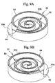
- FIG. 9A shows a fixed scroll 50 of the above application comprising an end plate 50a and a spiral wall body 50b provided on a side surface of the end plate 50a.
- FIG. 9B shows an orbiting scroll 51 similarly comprising an end plate 51a and a spiral wall body 51b provided on a side surface of the end plate 51a.
- a step portion 52 is provided on the side surface of the end plate 50a of the fixed scroll 50.
- the step portion 52 has two parts in which one part is high at the center of the side surface of the end plate 50a and the other part is low at the outer end of the end plate 50a.
- a step portion 53 is provided on a spiral top edge of the wall body 50b of the fixed scroll 50.
- the step portion 53 has two parts in which one part is high at the center of the spiral top edge and the other part is low at the outer end of the spiral top edge.
- a step portion 52 is provided on the side surface of the end plate 51 a of the orbiting scroll 51.
- the step portion 52 has two parts in which one part is high at the center of the side surface of the end plate 51a and the other part is low at the outer end of the end plate 51a. Furthermore, corresponding to the end plate 51a of the step portion 52, a step portion 53 is provided on a spiral top edge of the wall body 51b of the orbiting scroll 51. The step portion 53 has two parts in which one part is high at the center of the spiral top edge and the other part is low at the outer end of the spiral top edge.
- FIG. 10A is a plan view of the orbiting scroll and FIG. 10B is a cross-sectional view taken along line I-I of FIG. 10A.
- the perpendicular length (lap length) of the wall body which is further out than the step portion 52 is represented by H.
- the step difference of the step portion 52 is represented by L.
- the perpendicular length (lap length) of the wall body which is further in than the step portion 52 is represented by H2.
- the lap length H of the wall body which is further out than the step portion 52 is longer than the lap length H2 of the wall body which is further in than the step portion 52.
- the maximum capacity of the compression chamber P increases as the lap length of the wall body which is further out than the step portion 52 becomes larger, in comparison with the maximum capacity of the compression chamber having the uniform lap length. Consequently, the compression ratio Vi in the design can be increased without increasing the number of spiral laps of the wall body. Furthermore, since the lap length of each step is short, concentration of stress can be avoided.
- an object of the present invention is to provide a scroll compressor in which the compression efficiency is increased.
- An aspect according to the present invention is to provide a scroll compressor comprising a fixed scroll which is fixed in position and has a spiral wall body provided on one side surface of an end plate; an orbiting scroll which has a spiral wall body provided on one side surface of an end plate, being supported by engaging of the wall bodies so as to orbit and revolve around the fixed scroll without rotation; a first step portion provided on the end plate of one of the fixed scroll and the orbiting scroll, being at a high level at a center side and at a low level at an outer end side along the spiral wall body on one side surface of the end plate; and a second step portion provided on a top edge of the wall body of the other of the fixed scroll and the orbiting scroll by dividing the top edge into plural parts, the second step portion being at a high level to at a low level from the outer end to the center in correspondence with the first step portion, wherein, when a length of the wall body is represented by H at the outer side from the first step portion and a step difference of the step portion is represented by L in the one scroll, L
- FIG. 12 is a graph showing a relationship between L/H and compression efficiency. As shown in FIG. 12, if L/H is 0.2 or less, a superior scroll compressor is obtained by preventing decrease of the compression efficiency and avoiding concentration of stress. Furthermore, the scroll compressor has satisfactory compression efficiency by avoiding leakage of refrigerant.
- FIG. 1 shows a configuration of a back pressure scroll compressor as an embodiment of the present invention.
- the scroll compressor comprises an airtight housing 1, a discharging cover 2 which separates the housing I into a high pressure chamber (HR) and a low pressure chamber (LR), a frame 5, a suction pipe 6, a discharge pipe 7, a motor 8, a rotating shaft 9, and a mechanism preventing rotation 10.
- the scroll compressor has a fixed scroll 12 and an orbiting scroll 13 which is engaged with the fixed scroll 12.
- the fixed scroll 12 comprises a spiral wall body 12b provided on a side surface of an end plate 12a.
- the orbiting scroll 13 similarly comprises a spiral wall body 13b provided on a side surface of an end plate 13a, in particular, the wall body 13b being identical in shape to the wall body 12b of the fixed scroll 12.
- the orbiting scroll 13 is eccentrically provided against the fixed scroll 12 by the revolution radius and is engaged to the fixed scroll 12 with a phase shift of 180 degrees by engaging the wall bodies 12b and 13b.
- the fixed scroll 12 is not completely secured to the frame 5 with a bolt or the like, and therefore, the fixed scroll 12 is movable within a predetermined area.
- a cylindrical boss A is provided at the other side face of the end plate 13a of the orbiting scroll 13 (while the wall body 13b is provided on one side face of the end plate 13a).
- the eccentric section 9a which is provided at the upper end of the rotating shaft 9 driven by the motor 4, is accommodated in the boss A so as to freely rotate therein. Thereby, the orbiting scroll 13 orbits around the fixed scroll 12 and its rotation is prevented by the mechanism preventing rotation 10.
- the fixed scroll 12 is supported to the frame 5 via a compressed spring (an elastic body) so as to freely move and is pressed to the orbiting scroll 13.
- a discharge port 15 for discharging compressed fluid is provided in the center of the back of the end plate 12a.
- a cylindrical flange 16 which is projected from the back surface of the end plate 12a of the fixed scroll 12 is provided and is engaged with a cylindrical flange 17 provided at the discharge cover 2.
- the engaging part of the cylindrical flanges 16 and 17 has a sealing structure by a sealing member 18, so that the chamber is separated into the high pressure chamber (HR) and the low pressure chamber (LR) and the fixed scroll 12 needs to be pressed downward by supplying high pressure (back pressure) to the back surface of the fixed scroll.
- the sealing member 18 has a U-shape in cross-sectional view; the high pressure chamber (HR) further acts as a back pressure room for supplying high discharging pressure at the back surface of the fixed scroll 12.
- the end plate 12a of the fixed scroll 12 comprises a step portion 42 provided on one side surface on which the wall body 12b is provided so that the step portion 42 has two parts in which one part is high at the center side of the top edge of the spiral wall body 12b and the other part is low at the outer end side of the top edge of the spiral wall body 12b.
- the end plate 13a of the orbiting scroll 13 similarly comprises a step portion 43 provided on one side surface on which the wall body 13b is provided so that the step portion 43 has two parts in which one part is high at the center side of the top edge of the spiral wall body 13b and the other part is low at the outer end side of the top edge of the spiral wall body 13b.
- the bottom surface of the end plate 12a is divided into two parts of a bottom surface 12f having short length between the top edge of the wall body and the bottom surface 12f, and the bottom surface 12g having long length between the top edge of the wall body and the bottom surface 12g.
- the bottom surface 12f is provided at the center side of the spiral wall body 12b, and the bottom surface 12g is provided at the outer end side of the spiral wall body 12b.
- the step portion 42 is provided between the adjacent bottom surfaces 12f and 12g and a connecting wall surface 12h which connects the bottom surfaces 12f and 12g is provided so as to be perpendicular to the bottom surfaces 12f and 12g.
- the bottom surface of the end plate 13a is similarly divided into two parts of a bottom surface 13f having short length between the top edge of the wall body and the bottom surface 13f, and the bottom surface 13g having long length between the top edge of the wall body and the bottom surface 13g.
- the bottom surface 13f is provided at the center side of the spiral wall body 13b and the bottom surface 13g is provided at the outer end side of the spiral wall body 13b.
- the step portion 43 is provided between the adjacent bottom surfaces 13f and 13g and a connecting wall face 13h which connects the bottom surfaces 13f and 13g is provided so as to be perpendicular to the bottom surfaces 13f and 13g.
- FIG. 4A is a plan view of the orbiting scroll 13 and FIG. 4B is a cross-sectional view taken along line II-II of FIG. 4A.
- the orbiting scroll 13 will be explained as follows.
- the fixed scroll 12 has components which are similar to those of the orbiting scroll 13.
- the perpendicular length of the spiral wall body 13b which is further out than the step portion 43 is represented by H
- the perpendicular length of the spiral wall body 13b which is further in than the step portion 43 is represented by H2
- the step difference of the step portion 43 that is to say, the perpendicular length of the connecting wall face 13h is represented by L.
- H and L are predetermined within the following range.
- FIG. 12 a graph obtained by analyzing a relationship between L/H and a compression efficiency. As shown in FIG. 12, if L/H is too large, the amount of leakage of refrigerant through the step portion 43 increases and then, compression efficiency decreases. To avoid decreasing compression efficiency, H and L in the present invention is predetermined so that L/H ⁇ 0.2.
- the spiral top edge of the wall body 12b of the fixed scroll 12 is divided into two parts corresponding to the step portion 43 of the orbiting scroll 13 and is low at the center side and high at the outer side, so that a step portion 44 is obtained.
- the spiral top edge of the wall body 13b of the orbiting scroll is similarly divided into two parts corresponding to the step portion 42 of the fixed scroll 12 and is low at the center side and high at the outer side, so that a step portion 45 is obtained.
- the top edge of the wall body 12b is divided into two portions of the lower top edge 12c provided at the center side of the spiral wall body 12b and the higher top edge 12d provided at the outer side of the spiral wall body 12b.
- a connecting edge 12e which connects the adjacent top edges 12c and 12d is provided therebetween so as to be perpendicular to the rotating surface.
- the top edge of the wall body 13b is similarly divided into two portions of the lower top edge 13c provided at the center side of the spiral wall body 13b and the higher top edge 13d provided at the outer side of the spiral wall body 13b.
- a connecting edge 13e which connects the adjacent top edges 13c and 13d is provided therebetween so as to be perpendicular to the rotating surface.
- the connecting edge 12e When the wall body 12b is seen from the direction of the orbiting scroll 13, the connecting edge 12e is smoothly connected to the inner and outer side surfaces of the wall body 12b, and is a semicircle having a diameter equal to the thickness of the wall body 12b. Similarly, when the wall body 13b is seen from the direction of the fixed scroll 12, the connecting edge 13e is smoothly connected to the inner and outer side surfaces of the wall body 13b, and is a semicircle having a diameter equal to the thickness of the wall body 13b.
- the shape of the connecting wall surface 12h is a circular arc which matches the envelope curve drawn by the connecting edge 13e as the orbiting scroll 13 orbits.
- the shape of the connecting wall surface 13h is a circular arc which matches the envelope curve drawn by the connecting edge 12e.
- a tip seal is not provided on the top edges of the wall body 12b of the fixed scroll 12 and the wall body 13b of the orbiting scroll 13.
- the airtightness of a compression chamber C (explained later) is maintained by compressing the end surfaces of the wall bodies 12b and 13b with the end plates 12a and 13a.
- a compression chamber C is formed by partitioning the space in the compressor by the end plates 12a and 13a, and the wall bodies 12b and 13b, which face each other between the two scrolls.
- the compression chamber C moves from the outer end toward the center as the orbiting scroll 13 rotates. While the contact points of the wall bodies 12b and 13b are nearer the outer end than the connecting edge 12e, the connecting edge 12e slides against the connecting wall surface 13h so that there is no leakage of fluid between the compression chambers C (one of which is not airtight), which are adjacent to each other with the wall body 12 therebetween. While the contact points of the wall bodies 12b and 13b are not nearer the outer end than the connecting edge 12e, the connecting edge 12e does not slide against the connecting wall surface 13h so that equal pressure is maintained in the compression chambers C (both of which are airtight), which are adjacent to each other with the wall body 12 therebetween.
- the connecting edge 13e slides against the connecting wall surface 12h so that there is no leakage of fluid between the compression chambers C (one of which is not airtight), which are adjacent with the wall body 13 therebetween. While the contact points of the wall bodies 12b and 13b are not nearer the outer end than the connecting edge 13e, the connecting edge 13e does not slide against the connecting wall surface 12h so that equal pressure is maintained in the compression chambers C (both of which are airtight), which are adjacent with the wall body 13 therebetween. Additionally, the connecting edge 12e slides against the connecting wall surface 13h at the same time as the connecting edge 13e slides against the connecting wall surface 12h during a half-orbit of the orbiting scroll 13.
- the outer end of the wall body 12b directly contacts the outer side surface of the wall body 13b, and the outer end of the wall body 13b directly contacts the outer side surface of the wall body 12b; the fluid is injected between the end plates 12a and 13a, and the wall bodies 12b and 13b, forming two large-capacity compression chambers C at exactly opposite positions on either side of the center of the scroll compressor mechanism.
- the connecting edge 12e slides against the connecting wall surface 13h, and the connecting edge 13e slides against the connecting wall surface 12h, but this sliding ends immediately afterwards.
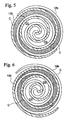
- FIG. 6 shows the state when the orbiting scroll 13 has orbited by ⁇ /2 from the state shown in FIG. 5.
- the compression chamber C moves toward the center with its airtightness intact while compressing the fluid by the gradual reduction of its capacity; the compression chamber C0 preceding the compression chamber C also moves toward the center with its airtightness intact while continuing to compress the fluid by the gradual reduction of its capacity.
- the sliding contact between the connecting edge 12e and the connecting wall surface 13h, and between the connecting edge 13e and the connecting wall surface 12h, ends in this process, and the two compression chambers C, which are adjacent to each other, are joined together with equal pressure.
- FIG. 7 shows the state when the orbiting scroll 13 has orbited by ⁇ /2 from the state shown in FIG. 6.
- the compression chamber C moves toward the center with its airtightness intact while compressing the fluid by the gradual reduction of its capacity; the compression chamber C0 preceding the compression chamber C also moves toward the center with its airtightness intact while continuing to compress the fluid by the gradual reduction of its capacity.
- the connecting edge 12e starts to slide against the connecting wall surface 13h, and the connecting edge 13e starts to slide against the connecting wall surface 12h in this process.
- a space C1 is formed between the inner side surface of the wall body 12b, which is near the outer peripheral end, and the outer side surface of the wall body 13b, positioned on the inner side of the inner side surface of the wall body 12b; this space C1 becomes a compression chamber later.
- a space C1 is formed between the inner side surface of the wall body 13b, which is near the outer peripheral end, and the outer side surface of the wall body 12b, positioned on the inner side of the inner side surface of the wall body 13b; the space C1 also becomes a compression chamber later.
- a low-pressure fluid is fed into the space C1 from the low pressure chamber (LR).
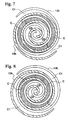
- FIG. 8 shows the state when the orbiting scroll 13 has orbited by ⁇ /2 from the state shown in FIG. 7.
- the space C1 increases in size while moving toward the center of the scroll compressor mechanism; the compression chamber C preceding the space C1 also moves toward the center while compressing the fluid by the gradual reduction of its capacity.
- FIG. 5 shows the state when the orbiting scroll 13 has orbited by ⁇ /2 from the state shown in FIG. 8.
- the space C1 further increases in size while moving toward the center of the scroll compressor mechanism; the compression chamber C preceding the space C1 also moves toward the center with its airtightness intact while compressing the fluid by the gradual reduction of its capacity.
- the compression chamber C0 shown in FIG. 5 becomes equal to the compression chamber C shown in FIG. 8, and the space C1 shown in FIG. 8 becomes equal to the compression chamber C shown in FIG. 5.
- the compression chamber reaches its minimum capacity and the fluid is discharged from the compression chamber C.
- the fluid discharged is introduced into the high pressure chamber (HR).
- the fixed scroll 12 is pressed to the orbiting scroll 13 with high back pressure.
- the sealing member 15 is widened due to differential pressure generated by introducing the fluid having high pressure into the U-shaped part.
- the high pressure chamber (HR) and the low pressure chamber (LR) is sealed by compressing the surface of the sealing member 15 against the peripheral surfaces of the cylindrical flanges 16 and 17.
- the height H of the outer side wall body provided further out than the step portion is predetermined so that L/H ⁇ 0.2, the loss generated by leakage of the fluid is prevented, and as a result, compression can be carried out with excellent compression efficiency.
- volume variation of the compression chamber is not caused only by decrease of the cross-sectional area which is parallel to the orbiting face of the scroll, but variation is synergisticly caused by decrease of the width in the direction of the orbiting axis, of the compression chamber and decrease of the cross-sectional area.
- a difference is provided between the lap length of each wall body 12b and 13b at the outer end side, which is further out than the step portion, and the lap length of each wall body 12b and 13b at the center side, which is further in than the step portion, and then the maximum capacity of the compression chamber C is increased and the minimum capacity of the compression chamber C is decreased.
- compression ratio of the scroll compressor is improved in comparison with the compression ratio of the conventional scroll compressor having the uniform lap length of the wall bodies, concentration of stress is avoided, so that a superior scroll compressor is obtained.
- a back pressure scroll compressor is mentioned as an embodiment; however, the present invention is not limited the above embodiment, and any scroll compressor can be adopted as long as the scroll compressor has step portions in the scrolls. Furthermore, considering lap strength (stress of lap), H and L may be determined accordingly.
Landscapes
- Engineering & Computer Science (AREA)
- Mechanical Engineering (AREA)
- General Engineering & Computer Science (AREA)
- Rotary Pumps (AREA)
Applications Claiming Priority (2)
| Application Number | Priority Date | Filing Date | Title |
|---|---|---|---|
| JP2001010391 | 2001-01-18 | ||
| JP2001010391A JP4709400B2 (ja) | 2001-01-18 | 2001-01-18 | スクロール圧縮機 |
Publications (2)
| Publication Number | Publication Date |
|---|---|
| EP1225339A2 true EP1225339A2 (de) | 2002-07-24 |
| EP1225339A3 EP1225339A3 (de) | 2004-01-21 |
Family
ID=18877708
Family Applications (1)
| Application Number | Title | Priority Date | Filing Date |
|---|---|---|---|
| EP02290102A Withdrawn EP1225339A3 (de) | 2001-01-18 | 2002-01-15 | Spiralverdichter |
Country Status (5)
| Country | Link |
|---|---|
| US (1) | US6527527B2 (de) |
| EP (1) | EP1225339A3 (de) |
| JP (1) | JP4709400B2 (de) |
| KR (1) | KR100437003B1 (de) |
| CN (1) | CN1240943C (de) |
Families Citing this family (6)
| Publication number | Priority date | Publication date | Assignee | Title |
|---|---|---|---|---|
| US6585501B2 (en) * | 2000-11-06 | 2003-07-01 | Mitsubishi Heavy Industries, Ltd. | Scroll compressor sealing |
| DE10203150A1 (de) * | 2002-01-28 | 2003-07-31 | Harting Electro Optics Gmbh & | Steckverbinder mit verschiebbaren Kontaktelementen |
| KR100695822B1 (ko) * | 2004-12-23 | 2007-03-20 | 엘지전자 주식회사 | 스크롤 압축기의 계단형 용량 가변장치 |
| JP6021373B2 (ja) | 2012-03-23 | 2016-11-09 | 三菱重工業株式会社 | スクロール圧縮機およびそのスクロールの加工方法 |
| JP6532713B2 (ja) * | 2015-03-12 | 2019-06-19 | 三菱重工サーマルシステムズ株式会社 | スクロール圧縮機 |
| CN114488416A (zh) * | 2020-08-27 | 2022-05-13 | 华为技术有限公司 | 光纤连接器插头、光纤适配器、连接器组件及通信设备 |
Citations (1)
| Publication number | Priority date | Publication date | Assignee | Title |
|---|---|---|---|---|
| JPH0617956A (ja) | 1992-06-30 | 1994-01-25 | Akio Oba | ソレノイドバルブ |
Family Cites Families (8)
| Publication number | Priority date | Publication date | Assignee | Title |
|---|---|---|---|---|
| JPS6017956B2 (ja) * | 1981-08-18 | 1985-05-08 | サンデン株式会社 | スクロ−ル型圧縮機 |
| JPS5963389A (ja) * | 1982-10-05 | 1984-04-11 | Hitachi Ltd | 容積形スクロ−ル式流体機械 |
| US4477238A (en) * | 1983-02-23 | 1984-10-16 | Sanden Corporation | Scroll type compressor with wrap portions of different axial heights |
| JPS6017956A (ja) | 1983-07-11 | 1985-01-29 | Agency Of Ind Science & Technol | 耐放射線半導体素子 |
| JPH04311693A (ja) | 1991-04-11 | 1992-11-04 | Toshiba Corp | スクロールコンプレッサ |
| JPH0571477A (ja) * | 1991-09-13 | 1993-03-23 | Toshiba Corp | スクロールコンプレツサ |
| JPH0828461A (ja) | 1994-07-11 | 1996-01-30 | Toshiba Corp | スクロール膨張機 |
| JPH09112456A (ja) | 1995-10-20 | 1997-05-02 | Sanden Corp | スクロール型圧縮機 |
-
2001
- 2001-01-18 JP JP2001010391A patent/JP4709400B2/ja not_active Expired - Lifetime
- 2001-10-25 KR KR10-2001-0065837A patent/KR100437003B1/ko not_active Expired - Fee Related
-
2002
- 2002-01-09 US US10/040,622 patent/US6527527B2/en not_active Expired - Lifetime
- 2002-01-14 CN CNB021016526A patent/CN1240943C/zh not_active Expired - Lifetime
- 2002-01-15 EP EP02290102A patent/EP1225339A3/de not_active Withdrawn
Patent Citations (1)
| Publication number | Priority date | Publication date | Assignee | Title |
|---|---|---|---|---|
| JPH0617956A (ja) | 1992-06-30 | 1994-01-25 | Akio Oba | ソレノイドバルブ |
Also Published As
| Publication number | Publication date |
|---|---|
| JP4709400B2 (ja) | 2011-06-22 |
| EP1225339A3 (de) | 2004-01-21 |
| US6527527B2 (en) | 2003-03-04 |
| KR100437003B1 (ko) | 2004-07-02 |
| CN1366139A (zh) | 2002-08-28 |
| JP2002213371A (ja) | 2002-07-31 |
| CN1240943C (zh) | 2006-02-08 |
| KR20020062128A (ko) | 2002-07-25 |
| US20020094290A1 (en) | 2002-07-18 |
Similar Documents
| Publication | Publication Date | Title |
|---|---|---|
| EP1205665B1 (de) | Spiralverdichter | |
| JP4301713B2 (ja) | スクロール圧縮機 | |
| US7244114B2 (en) | Scroll compressor | |
| US6527527B2 (en) | Scroll compressor | |
| JP4410392B2 (ja) | スクロール圧縮機 | |
| JP3338886B2 (ja) | 密閉型電動スクロール圧縮機 | |
| EP3567212B1 (de) | Verdichter mit oldham-ring | |
| EP1293674B1 (de) | Spiralkompressor | |
| JP4475749B2 (ja) | スクロール圧縮機 | |
| JP2019143548A (ja) | スクロール流体機械 | |
| JP4709402B2 (ja) | スクロール圧縮機 | |
| JP2001221174A (ja) | スクロール流体機械 | |
| JPH045833B2 (de) | ||
| JP4410726B2 (ja) | スクロール圧縮機 | |
| EP2096310B1 (de) | Kompressor der spiralbauart | |
| JP3913072B2 (ja) | スクロール型圧縮機 | |
| WO2019163537A1 (ja) | スクロール流体機械 | |
| JP2019143546A (ja) | スクロール流体機械 | |
| JPH11264387A (ja) | スクロ―ル流体機械 | |
| JP2000073971A (ja) | スクロール圧縮機 | |
| JP2002138975A (ja) | スクロール圧縮機 | |
| JP2019143543A (ja) | スクロール流体機械 |
Legal Events
| Date | Code | Title | Description |
|---|---|---|---|
| PUAI | Public reference made under article 153(3) epc to a published international application that has entered the european phase |
Free format text: ORIGINAL CODE: 0009012 |
|
| AK | Designated contracting states |
Kind code of ref document: A2 Designated state(s): AT BE CH CY DE DK ES FI FR GB GR IE IT LI LU MC NL PT SE TR |
|
| AX | Request for extension of the european patent |
Free format text: AL;LT;LV;MK;RO;SI |
|
| PUAL | Search report despatched |
Free format text: ORIGINAL CODE: 0009013 |
|
| AK | Designated contracting states |
Kind code of ref document: A3 Designated state(s): AT BE CH CY DE DK ES FI FR GB GR IE IT LI LU MC NL PT SE TR |
|
| AX | Request for extension of the european patent |
Extension state: AL LT LV MK RO SI |
|
| 17P | Request for examination filed |
Effective date: 20040413 |
|
| AKX | Designation fees paid |
Designated state(s): DE FR GB IT NL SE |
|
| 17Q | First examination report despatched |
Effective date: 20041029 |
|
| STAA | Information on the status of an ep patent application or granted ep patent |
Free format text: STATUS: THE APPLICATION IS DEEMED TO BE WITHDRAWN |
|
| 18D | Application deemed to be withdrawn |
Effective date: 20060121 |