EP1225073A2 - Hybridfahrzeug und auswählbare Verfahren zu seinem Betrieb - Google Patents
Hybridfahrzeug und auswählbare Verfahren zu seinem Betrieb Download PDFInfo
- Publication number
- EP1225073A2 EP1225073A2 EP01310176A EP01310176A EP1225073A2 EP 1225073 A2 EP1225073 A2 EP 1225073A2 EP 01310176 A EP01310176 A EP 01310176A EP 01310176 A EP01310176 A EP 01310176A EP 1225073 A2 EP1225073 A2 EP 1225073A2
- Authority
- EP
- European Patent Office
- Prior art keywords
- vehicle
- internal combustion
- combustion engine
- generator
- engine
- Prior art date
- Legal status (The legal status is an assumption and is not a legal conclusion. Google has not performed a legal analysis and makes no representation as to the accuracy of the status listed.)
- Withdrawn
Links
Images


Classifications
-
- B—PERFORMING OPERATIONS; TRANSPORTING
- B60—VEHICLES IN GENERAL
- B60W—CONJOINT CONTROL OF VEHICLE SUB-UNITS OF DIFFERENT TYPE OR DIFFERENT FUNCTION; CONTROL SYSTEMS SPECIALLY ADAPTED FOR HYBRID VEHICLES; ROAD VEHICLE DRIVE CONTROL SYSTEMS FOR PURPOSES NOT RELATED TO THE CONTROL OF A PARTICULAR SUB-UNIT
- B60W20/00—Control systems specially adapted for hybrid vehicles
- B60W20/10—Controlling the power contribution of each of the prime movers to meet required power demand
- B60W20/13—Controlling the power contribution of each of the prime movers to meet required power demand in order to stay within battery power input or output limits; in order to prevent overcharging or battery depletion
-
- B—PERFORMING OPERATIONS; TRANSPORTING
- B60—VEHICLES IN GENERAL
- B60K—ARRANGEMENT OR MOUNTING OF PROPULSION UNITS OR OF TRANSMISSIONS IN VEHICLES; ARRANGEMENT OR MOUNTING OF PLURAL DIVERSE PRIME-MOVERS IN VEHICLES; AUXILIARY DRIVES FOR VEHICLES; INSTRUMENTATION OR DASHBOARDS FOR VEHICLES; ARRANGEMENTS IN CONNECTION WITH COOLING, AIR INTAKE, GAS EXHAUST OR FUEL SUPPLY OF PROPULSION UNITS IN VEHICLES
- B60K6/00—Arrangement or mounting of plural diverse prime-movers for mutual or common propulsion, e.g. hybrid propulsion systems comprising electric motors and internal combustion engines ; Control systems therefor, i.e. systems controlling two or more prime movers, or controlling one of these prime movers and any of the transmission, drive or drive units Informative references: mechanical gearings with secondary electric drive F16H3/72; arrangements for handling mechanical energy structurally associated with the dynamo-electric machine H02K7/00; machines comprising structurally interrelated motor and generator parts H02K51/00; dynamo-electric machines not otherwise provided for in H02K see H02K99/00
- B60K6/20—Arrangement or mounting of plural diverse prime-movers for mutual or common propulsion, e.g. hybrid propulsion systems comprising electric motors and internal combustion engines ; Control systems therefor, i.e. systems controlling two or more prime movers, or controlling one of these prime movers and any of the transmission, drive or drive units Informative references: mechanical gearings with secondary electric drive F16H3/72; arrangements for handling mechanical energy structurally associated with the dynamo-electric machine H02K7/00; machines comprising structurally interrelated motor and generator parts H02K51/00; dynamo-electric machines not otherwise provided for in H02K see H02K99/00 the prime-movers consisting of electric motors and internal combustion engines, e.g. HEVs
- B60K6/42—Arrangement or mounting of plural diverse prime-movers for mutual or common propulsion, e.g. hybrid propulsion systems comprising electric motors and internal combustion engines ; Control systems therefor, i.e. systems controlling two or more prime movers, or controlling one of these prime movers and any of the transmission, drive or drive units Informative references: mechanical gearings with secondary electric drive F16H3/72; arrangements for handling mechanical energy structurally associated with the dynamo-electric machine H02K7/00; machines comprising structurally interrelated motor and generator parts H02K51/00; dynamo-electric machines not otherwise provided for in H02K see H02K99/00 the prime-movers consisting of electric motors and internal combustion engines, e.g. HEVs characterised by the architecture of the hybrid electric vehicle
- B60K6/46—Series type
-
- B—PERFORMING OPERATIONS; TRANSPORTING
- B60—VEHICLES IN GENERAL
- B60K—ARRANGEMENT OR MOUNTING OF PROPULSION UNITS OR OF TRANSMISSIONS IN VEHICLES; ARRANGEMENT OR MOUNTING OF PLURAL DIVERSE PRIME-MOVERS IN VEHICLES; AUXILIARY DRIVES FOR VEHICLES; INSTRUMENTATION OR DASHBOARDS FOR VEHICLES; ARRANGEMENTS IN CONNECTION WITH COOLING, AIR INTAKE, GAS EXHAUST OR FUEL SUPPLY OF PROPULSION UNITS IN VEHICLES
- B60K11/00—Arrangement in connection with cooling of propulsion units
-
- B—PERFORMING OPERATIONS; TRANSPORTING
- B60—VEHICLES IN GENERAL
- B60L—PROPULSION OF ELECTRICALLY-PROPELLED VEHICLES; SUPPLYING ELECTRIC POWER FOR AUXILIARY EQUIPMENT OF ELECTRICALLY-PROPELLED VEHICLES; ELECTRODYNAMIC BRAKE SYSTEMS FOR VEHICLES IN GENERAL; MAGNETIC SUSPENSION OR LEVITATION FOR VEHICLES; MONITORING OPERATING VARIABLES OF ELECTRICALLY-PROPELLED VEHICLES; ELECTRIC SAFETY DEVICES FOR ELECTRICALLY-PROPELLED VEHICLES
- B60L50/00—Electric propulsion with power supplied within the vehicle
- B60L50/50—Electric propulsion with power supplied within the vehicle using propulsion power supplied by batteries or fuel cells
- B60L50/60—Electric propulsion with power supplied within the vehicle using propulsion power supplied by batteries or fuel cells using power supplied by batteries
- B60L50/61—Electric propulsion with power supplied within the vehicle using propulsion power supplied by batteries or fuel cells using power supplied by batteries by batteries charged by engine-driven generators, e.g. series hybrid electric vehicles
-
- B—PERFORMING OPERATIONS; TRANSPORTING
- B60—VEHICLES IN GENERAL
- B60W—CONJOINT CONTROL OF VEHICLE SUB-UNITS OF DIFFERENT TYPE OR DIFFERENT FUNCTION; CONTROL SYSTEMS SPECIALLY ADAPTED FOR HYBRID VEHICLES; ROAD VEHICLE DRIVE CONTROL SYSTEMS FOR PURPOSES NOT RELATED TO THE CONTROL OF A PARTICULAR SUB-UNIT
- B60W10/00—Conjoint control of vehicle sub-units of different type or different function
- B60W10/04—Conjoint control of vehicle sub-units of different type or different function including control of propulsion units
- B60W10/06—Conjoint control of vehicle sub-units of different type or different function including control of propulsion units including control of combustion engines
-
- B—PERFORMING OPERATIONS; TRANSPORTING
- B60—VEHICLES IN GENERAL
- B60W—CONJOINT CONTROL OF VEHICLE SUB-UNITS OF DIFFERENT TYPE OR DIFFERENT FUNCTION; CONTROL SYSTEMS SPECIALLY ADAPTED FOR HYBRID VEHICLES; ROAD VEHICLE DRIVE CONTROL SYSTEMS FOR PURPOSES NOT RELATED TO THE CONTROL OF A PARTICULAR SUB-UNIT
- B60W10/00—Conjoint control of vehicle sub-units of different type or different function
- B60W10/04—Conjoint control of vehicle sub-units of different type or different function including control of propulsion units
- B60W10/08—Conjoint control of vehicle sub-units of different type or different function including control of propulsion units including control of electric propulsion units, e.g. motors or generators
-
- B—PERFORMING OPERATIONS; TRANSPORTING
- B60—VEHICLES IN GENERAL
- B60W—CONJOINT CONTROL OF VEHICLE SUB-UNITS OF DIFFERENT TYPE OR DIFFERENT FUNCTION; CONTROL SYSTEMS SPECIALLY ADAPTED FOR HYBRID VEHICLES; ROAD VEHICLE DRIVE CONTROL SYSTEMS FOR PURPOSES NOT RELATED TO THE CONTROL OF A PARTICULAR SUB-UNIT
- B60W20/00—Control systems specially adapted for hybrid vehicles
-
- B—PERFORMING OPERATIONS; TRANSPORTING
- B60—VEHICLES IN GENERAL
- B60W—CONJOINT CONTROL OF VEHICLE SUB-UNITS OF DIFFERENT TYPE OR DIFFERENT FUNCTION; CONTROL SYSTEMS SPECIALLY ADAPTED FOR HYBRID VEHICLES; ROAD VEHICLE DRIVE CONTROL SYSTEMS FOR PURPOSES NOT RELATED TO THE CONTROL OF A PARTICULAR SUB-UNIT
- B60W50/00—Details of control systems for road vehicle drive control not related to the control of a particular sub-unit, e.g. process diagnostic or vehicle driver interfaces
- B60W50/08—Interaction between the driver and the control system
- B60W50/082—Selecting or switching between different modes of propelling
-
- F—MECHANICAL ENGINEERING; LIGHTING; HEATING; WEAPONS; BLASTING
- F02—COMBUSTION ENGINES; HOT-GAS OR COMBUSTION-PRODUCT ENGINE PLANTS
- F02D—CONTROLLING COMBUSTION ENGINES
- F02D41/00—Electrical control of supply of combustible mixture or its constituents
- F02D41/02—Circuit arrangements for generating control signals
- F02D41/04—Introducing corrections for particular operating conditions
- F02D41/042—Introducing corrections for particular operating conditions for stopping the engine
-
- B—PERFORMING OPERATIONS; TRANSPORTING
- B60—VEHICLES IN GENERAL
- B60K—ARRANGEMENT OR MOUNTING OF PROPULSION UNITS OR OF TRANSMISSIONS IN VEHICLES; ARRANGEMENT OR MOUNTING OF PLURAL DIVERSE PRIME-MOVERS IN VEHICLES; AUXILIARY DRIVES FOR VEHICLES; INSTRUMENTATION OR DASHBOARDS FOR VEHICLES; ARRANGEMENTS IN CONNECTION WITH COOLING, AIR INTAKE, GAS EXHAUST OR FUEL SUPPLY OF PROPULSION UNITS IN VEHICLES
- B60K1/00—Arrangement or mounting of electrical propulsion units
- B60K1/02—Arrangement or mounting of electrical propulsion units comprising more than one electric motor
-
- B—PERFORMING OPERATIONS; TRANSPORTING
- B60—VEHICLES IN GENERAL
- B60K—ARRANGEMENT OR MOUNTING OF PROPULSION UNITS OR OF TRANSMISSIONS IN VEHICLES; ARRANGEMENT OR MOUNTING OF PLURAL DIVERSE PRIME-MOVERS IN VEHICLES; AUXILIARY DRIVES FOR VEHICLES; INSTRUMENTATION OR DASHBOARDS FOR VEHICLES; ARRANGEMENTS IN CONNECTION WITH COOLING, AIR INTAKE, GAS EXHAUST OR FUEL SUPPLY OF PROPULSION UNITS IN VEHICLES
- B60K6/00—Arrangement or mounting of plural diverse prime-movers for mutual or common propulsion, e.g. hybrid propulsion systems comprising electric motors and internal combustion engines ; Control systems therefor, i.e. systems controlling two or more prime movers, or controlling one of these prime movers and any of the transmission, drive or drive units Informative references: mechanical gearings with secondary electric drive F16H3/72; arrangements for handling mechanical energy structurally associated with the dynamo-electric machine H02K7/00; machines comprising structurally interrelated motor and generator parts H02K51/00; dynamo-electric machines not otherwise provided for in H02K see H02K99/00
- B60K6/20—Arrangement or mounting of plural diverse prime-movers for mutual or common propulsion, e.g. hybrid propulsion systems comprising electric motors and internal combustion engines ; Control systems therefor, i.e. systems controlling two or more prime movers, or controlling one of these prime movers and any of the transmission, drive or drive units Informative references: mechanical gearings with secondary electric drive F16H3/72; arrangements for handling mechanical energy structurally associated with the dynamo-electric machine H02K7/00; machines comprising structurally interrelated motor and generator parts H02K51/00; dynamo-electric machines not otherwise provided for in H02K see H02K99/00 the prime-movers consisting of electric motors and internal combustion engines, e.g. HEVs
- B60K6/22—Arrangement or mounting of plural diverse prime-movers for mutual or common propulsion, e.g. hybrid propulsion systems comprising electric motors and internal combustion engines ; Control systems therefor, i.e. systems controlling two or more prime movers, or controlling one of these prime movers and any of the transmission, drive or drive units Informative references: mechanical gearings with secondary electric drive F16H3/72; arrangements for handling mechanical energy structurally associated with the dynamo-electric machine H02K7/00; machines comprising structurally interrelated motor and generator parts H02K51/00; dynamo-electric machines not otherwise provided for in H02K see H02K99/00 the prime-movers consisting of electric motors and internal combustion engines, e.g. HEVs characterised by apparatus, components or means specially adapted for HEVs
- B60K6/26—Arrangement or mounting of plural diverse prime-movers for mutual or common propulsion, e.g. hybrid propulsion systems comprising electric motors and internal combustion engines ; Control systems therefor, i.e. systems controlling two or more prime movers, or controlling one of these prime movers and any of the transmission, drive or drive units Informative references: mechanical gearings with secondary electric drive F16H3/72; arrangements for handling mechanical energy structurally associated with the dynamo-electric machine H02K7/00; machines comprising structurally interrelated motor and generator parts H02K51/00; dynamo-electric machines not otherwise provided for in H02K see H02K99/00 the prime-movers consisting of electric motors and internal combustion engines, e.g. HEVs characterised by apparatus, components or means specially adapted for HEVs characterised by the motors or the generators
- B60K2006/268—Electric drive motor starts the engine, i.e. used as starter motor
-
- B—PERFORMING OPERATIONS; TRANSPORTING
- B60—VEHICLES IN GENERAL
- B60L—PROPULSION OF ELECTRICALLY-PROPELLED VEHICLES; SUPPLYING ELECTRIC POWER FOR AUXILIARY EQUIPMENT OF ELECTRICALLY-PROPELLED VEHICLES; ELECTRODYNAMIC BRAKE SYSTEMS FOR VEHICLES IN GENERAL; MAGNETIC SUSPENSION OR LEVITATION FOR VEHICLES; MONITORING OPERATING VARIABLES OF ELECTRICALLY-PROPELLED VEHICLES; ELECTRIC SAFETY DEVICES FOR ELECTRICALLY-PROPELLED VEHICLES
- B60L2210/00—Converter types
- B60L2210/30—AC to DC converters
-
- B—PERFORMING OPERATIONS; TRANSPORTING
- B60—VEHICLES IN GENERAL
- B60L—PROPULSION OF ELECTRICALLY-PROPELLED VEHICLES; SUPPLYING ELECTRIC POWER FOR AUXILIARY EQUIPMENT OF ELECTRICALLY-PROPELLED VEHICLES; ELECTRODYNAMIC BRAKE SYSTEMS FOR VEHICLES IN GENERAL; MAGNETIC SUSPENSION OR LEVITATION FOR VEHICLES; MONITORING OPERATING VARIABLES OF ELECTRICALLY-PROPELLED VEHICLES; ELECTRIC SAFETY DEVICES FOR ELECTRICALLY-PROPELLED VEHICLES
- B60L2210/00—Converter types
- B60L2210/40—DC to AC converters
-
- B—PERFORMING OPERATIONS; TRANSPORTING
- B60—VEHICLES IN GENERAL
- B60L—PROPULSION OF ELECTRICALLY-PROPELLED VEHICLES; SUPPLYING ELECTRIC POWER FOR AUXILIARY EQUIPMENT OF ELECTRICALLY-PROPELLED VEHICLES; ELECTRODYNAMIC BRAKE SYSTEMS FOR VEHICLES IN GENERAL; MAGNETIC SUSPENSION OR LEVITATION FOR VEHICLES; MONITORING OPERATING VARIABLES OF ELECTRICALLY-PROPELLED VEHICLES; ELECTRIC SAFETY DEVICES FOR ELECTRICALLY-PROPELLED VEHICLES
- B60L2220/00—Electrical machine types; Structures or applications thereof
- B60L2220/10—Electrical machine types
- B60L2220/14—Synchronous machines
-
- B—PERFORMING OPERATIONS; TRANSPORTING
- B60—VEHICLES IN GENERAL
- B60L—PROPULSION OF ELECTRICALLY-PROPELLED VEHICLES; SUPPLYING ELECTRIC POWER FOR AUXILIARY EQUIPMENT OF ELECTRICALLY-PROPELLED VEHICLES; ELECTRODYNAMIC BRAKE SYSTEMS FOR VEHICLES IN GENERAL; MAGNETIC SUSPENSION OR LEVITATION FOR VEHICLES; MONITORING OPERATING VARIABLES OF ELECTRICALLY-PROPELLED VEHICLES; ELECTRIC SAFETY DEVICES FOR ELECTRICALLY-PROPELLED VEHICLES
- B60L2220/00—Electrical machine types; Structures or applications thereof
- B60L2220/10—Electrical machine types
- B60L2220/16—DC brushless machines
-
- B—PERFORMING OPERATIONS; TRANSPORTING
- B60—VEHICLES IN GENERAL
- B60L—PROPULSION OF ELECTRICALLY-PROPELLED VEHICLES; SUPPLYING ELECTRIC POWER FOR AUXILIARY EQUIPMENT OF ELECTRICALLY-PROPELLED VEHICLES; ELECTRODYNAMIC BRAKE SYSTEMS FOR VEHICLES IN GENERAL; MAGNETIC SUSPENSION OR LEVITATION FOR VEHICLES; MONITORING OPERATING VARIABLES OF ELECTRICALLY-PROPELLED VEHICLES; ELECTRIC SAFETY DEVICES FOR ELECTRICALLY-PROPELLED VEHICLES
- B60L2240/00—Control parameters of input or output; Target parameters
- B60L2240/10—Vehicle control parameters
- B60L2240/36—Temperature of vehicle components or parts
-
- B—PERFORMING OPERATIONS; TRANSPORTING
- B60—VEHICLES IN GENERAL
- B60L—PROPULSION OF ELECTRICALLY-PROPELLED VEHICLES; SUPPLYING ELECTRIC POWER FOR AUXILIARY EQUIPMENT OF ELECTRICALLY-PROPELLED VEHICLES; ELECTRODYNAMIC BRAKE SYSTEMS FOR VEHICLES IN GENERAL; MAGNETIC SUSPENSION OR LEVITATION FOR VEHICLES; MONITORING OPERATING VARIABLES OF ELECTRICALLY-PROPELLED VEHICLES; ELECTRIC SAFETY DEVICES FOR ELECTRICALLY-PROPELLED VEHICLES
- B60L2240/00—Control parameters of input or output; Target parameters
- B60L2240/40—Drive Train control parameters
- B60L2240/44—Drive Train control parameters related to combustion engines
- B60L2240/441—Speed
-
- B—PERFORMING OPERATIONS; TRANSPORTING
- B60—VEHICLES IN GENERAL
- B60L—PROPULSION OF ELECTRICALLY-PROPELLED VEHICLES; SUPPLYING ELECTRIC POWER FOR AUXILIARY EQUIPMENT OF ELECTRICALLY-PROPELLED VEHICLES; ELECTRODYNAMIC BRAKE SYSTEMS FOR VEHICLES IN GENERAL; MAGNETIC SUSPENSION OR LEVITATION FOR VEHICLES; MONITORING OPERATING VARIABLES OF ELECTRICALLY-PROPELLED VEHICLES; ELECTRIC SAFETY DEVICES FOR ELECTRICALLY-PROPELLED VEHICLES
- B60L2240/00—Control parameters of input or output; Target parameters
- B60L2240/40—Drive Train control parameters
- B60L2240/44—Drive Train control parameters related to combustion engines
- B60L2240/445—Temperature
-
- B—PERFORMING OPERATIONS; TRANSPORTING
- B60—VEHICLES IN GENERAL
- B60W—CONJOINT CONTROL OF VEHICLE SUB-UNITS OF DIFFERENT TYPE OR DIFFERENT FUNCTION; CONTROL SYSTEMS SPECIALLY ADAPTED FOR HYBRID VEHICLES; ROAD VEHICLE DRIVE CONTROL SYSTEMS FOR PURPOSES NOT RELATED TO THE CONTROL OF A PARTICULAR SUB-UNIT
- B60W2510/00—Input parameters relating to a particular sub-units
- B60W2510/06—Combustion engines, Gas turbines
- B60W2510/0614—Position of fuel or air injector
- B60W2510/0628—Inlet air flow rate
-
- B—PERFORMING OPERATIONS; TRANSPORTING
- B60—VEHICLES IN GENERAL
- B60W—CONJOINT CONTROL OF VEHICLE SUB-UNITS OF DIFFERENT TYPE OR DIFFERENT FUNCTION; CONTROL SYSTEMS SPECIALLY ADAPTED FOR HYBRID VEHICLES; ROAD VEHICLE DRIVE CONTROL SYSTEMS FOR PURPOSES NOT RELATED TO THE CONTROL OF A PARTICULAR SUB-UNIT
- B60W2510/00—Input parameters relating to a particular sub-units
- B60W2510/06—Combustion engines, Gas turbines
- B60W2510/0638—Engine speed
-
- B—PERFORMING OPERATIONS; TRANSPORTING
- B60—VEHICLES IN GENERAL
- B60W—CONJOINT CONTROL OF VEHICLE SUB-UNITS OF DIFFERENT TYPE OR DIFFERENT FUNCTION; CONTROL SYSTEMS SPECIALLY ADAPTED FOR HYBRID VEHICLES; ROAD VEHICLE DRIVE CONTROL SYSTEMS FOR PURPOSES NOT RELATED TO THE CONTROL OF A PARTICULAR SUB-UNIT
- B60W2510/00—Input parameters relating to a particular sub-units
- B60W2510/06—Combustion engines, Gas turbines
- B60W2510/0676—Engine temperature
-
- B—PERFORMING OPERATIONS; TRANSPORTING
- B60—VEHICLES IN GENERAL
- B60W—CONJOINT CONTROL OF VEHICLE SUB-UNITS OF DIFFERENT TYPE OR DIFFERENT FUNCTION; CONTROL SYSTEMS SPECIALLY ADAPTED FOR HYBRID VEHICLES; ROAD VEHICLE DRIVE CONTROL SYSTEMS FOR PURPOSES NOT RELATED TO THE CONTROL OF A PARTICULAR SUB-UNIT
- B60W2556/00—Input parameters relating to data
- B60W2556/10—Historical data
-
- B—PERFORMING OPERATIONS; TRANSPORTING
- B60—VEHICLES IN GENERAL
- B60W—CONJOINT CONTROL OF VEHICLE SUB-UNITS OF DIFFERENT TYPE OR DIFFERENT FUNCTION; CONTROL SYSTEMS SPECIALLY ADAPTED FOR HYBRID VEHICLES; ROAD VEHICLE DRIVE CONTROL SYSTEMS FOR PURPOSES NOT RELATED TO THE CONTROL OF A PARTICULAR SUB-UNIT
- B60W2710/00—Output or target parameters relating to a particular sub-units
- B60W2710/06—Combustion engines, Gas turbines
- B60W2710/0616—Position of fuel or air injector
-
- F—MECHANICAL ENGINEERING; LIGHTING; HEATING; WEAPONS; BLASTING
- F01—MACHINES OR ENGINES IN GENERAL; ENGINE PLANTS IN GENERAL; STEAM ENGINES
- F01P—COOLING OF MACHINES OR ENGINES IN GENERAL; COOLING OF INTERNAL-COMBUSTION ENGINES
- F01P2025/00—Measuring
- F01P2025/08—Temperature
- F01P2025/32—Engine outcoming fluid temperature
-
- F—MECHANICAL ENGINEERING; LIGHTING; HEATING; WEAPONS; BLASTING
- F01—MACHINES OR ENGINES IN GENERAL; ENGINE PLANTS IN GENERAL; STEAM ENGINES
- F01P—COOLING OF MACHINES OR ENGINES IN GENERAL; COOLING OF INTERNAL-COMBUSTION ENGINES
- F01P2050/00—Applications
- F01P2050/24—Hybrid vehicles
-
- F—MECHANICAL ENGINEERING; LIGHTING; HEATING; WEAPONS; BLASTING
- F01—MACHINES OR ENGINES IN GENERAL; ENGINE PLANTS IN GENERAL; STEAM ENGINES
- F01P—COOLING OF MACHINES OR ENGINES IN GENERAL; COOLING OF INTERNAL-COMBUSTION ENGINES
- F01P2060/00—Cooling circuits using auxiliaries
- F01P2060/18—Heater
- F01P2060/185—Heater for alternators or generators
-
- F—MECHANICAL ENGINEERING; LIGHTING; HEATING; WEAPONS; BLASTING
- F02—COMBUSTION ENGINES; HOT-GAS OR COMBUSTION-PRODUCT ENGINE PLANTS
- F02B—INTERNAL-COMBUSTION PISTON ENGINES; COMBUSTION ENGINES IN GENERAL
- F02B63/00—Adaptations of engines for driving pumps, hand-held tools or electric generators; Portable combinations of engines with engine-driven devices
- F02B63/04—Adaptations of engines for driving pumps, hand-held tools or electric generators; Portable combinations of engines with engine-driven devices for electric generators
-
- F—MECHANICAL ENGINEERING; LIGHTING; HEATING; WEAPONS; BLASTING
- F02—COMBUSTION ENGINES; HOT-GAS OR COMBUSTION-PRODUCT ENGINE PLANTS
- F02N—STARTING OF COMBUSTION ENGINES; STARTING AIDS FOR SUCH ENGINES, NOT OTHERWISE PROVIDED FOR
- F02N19/00—Starting aids for combustion engines, not otherwise provided for
-
- Y—GENERAL TAGGING OF NEW TECHNOLOGICAL DEVELOPMENTS; GENERAL TAGGING OF CROSS-SECTIONAL TECHNOLOGIES SPANNING OVER SEVERAL SECTIONS OF THE IPC; TECHNICAL SUBJECTS COVERED BY FORMER USPC CROSS-REFERENCE ART COLLECTIONS [XRACs] AND DIGESTS
- Y02—TECHNOLOGIES OR APPLICATIONS FOR MITIGATION OR ADAPTATION AGAINST CLIMATE CHANGE
- Y02T—CLIMATE CHANGE MITIGATION TECHNOLOGIES RELATED TO TRANSPORTATION
- Y02T10/00—Road transport of goods or passengers
- Y02T10/10—Internal combustion engine [ICE] based vehicles
- Y02T10/40—Engine management systems
-
- Y—GENERAL TAGGING OF NEW TECHNOLOGICAL DEVELOPMENTS; GENERAL TAGGING OF CROSS-SECTIONAL TECHNOLOGIES SPANNING OVER SEVERAL SECTIONS OF THE IPC; TECHNICAL SUBJECTS COVERED BY FORMER USPC CROSS-REFERENCE ART COLLECTIONS [XRACs] AND DIGESTS
- Y02—TECHNOLOGIES OR APPLICATIONS FOR MITIGATION OR ADAPTATION AGAINST CLIMATE CHANGE
- Y02T—CLIMATE CHANGE MITIGATION TECHNOLOGIES RELATED TO TRANSPORTATION
- Y02T10/00—Road transport of goods or passengers
- Y02T10/60—Other road transportation technologies with climate change mitigation effect
- Y02T10/62—Hybrid vehicles
-
- Y—GENERAL TAGGING OF NEW TECHNOLOGICAL DEVELOPMENTS; GENERAL TAGGING OF CROSS-SECTIONAL TECHNOLOGIES SPANNING OVER SEVERAL SECTIONS OF THE IPC; TECHNICAL SUBJECTS COVERED BY FORMER USPC CROSS-REFERENCE ART COLLECTIONS [XRACs] AND DIGESTS
- Y02—TECHNOLOGIES OR APPLICATIONS FOR MITIGATION OR ADAPTATION AGAINST CLIMATE CHANGE
- Y02T—CLIMATE CHANGE MITIGATION TECHNOLOGIES RELATED TO TRANSPORTATION
- Y02T10/00—Road transport of goods or passengers
- Y02T10/60—Other road transportation technologies with climate change mitigation effect
- Y02T10/70—Energy storage systems for electromobility, e.g. batteries
-
- Y—GENERAL TAGGING OF NEW TECHNOLOGICAL DEVELOPMENTS; GENERAL TAGGING OF CROSS-SECTIONAL TECHNOLOGIES SPANNING OVER SEVERAL SECTIONS OF THE IPC; TECHNICAL SUBJECTS COVERED BY FORMER USPC CROSS-REFERENCE ART COLLECTIONS [XRACs] AND DIGESTS
- Y02—TECHNOLOGIES OR APPLICATIONS FOR MITIGATION OR ADAPTATION AGAINST CLIMATE CHANGE
- Y02T—CLIMATE CHANGE MITIGATION TECHNOLOGIES RELATED TO TRANSPORTATION
- Y02T10/00—Road transport of goods or passengers
- Y02T10/60—Other road transportation technologies with climate change mitigation effect
- Y02T10/7072—Electromobility specific charging systems or methods for batteries, ultracapacitors, supercapacitors or double-layer capacitors
-
- Y—GENERAL TAGGING OF NEW TECHNOLOGICAL DEVELOPMENTS; GENERAL TAGGING OF CROSS-SECTIONAL TECHNOLOGIES SPANNING OVER SEVERAL SECTIONS OF THE IPC; TECHNICAL SUBJECTS COVERED BY FORMER USPC CROSS-REFERENCE ART COLLECTIONS [XRACs] AND DIGESTS
- Y02—TECHNOLOGIES OR APPLICATIONS FOR MITIGATION OR ADAPTATION AGAINST CLIMATE CHANGE
- Y02T—CLIMATE CHANGE MITIGATION TECHNOLOGIES RELATED TO TRANSPORTATION
- Y02T10/00—Road transport of goods or passengers
- Y02T10/60—Other road transportation technologies with climate change mitigation effect
- Y02T10/72—Electric energy management in electromobility
Definitions
- the invention relates to methods and apparatus for adaptably controlling the series hybrid electric vehicle.
- Compressed natural gas has been used as an alternative fuel. Compressed natural gas does not produce as much power in conventional internal combustion engines as gasoline and diesel and has not been widely developed or accepted as an alternative to gasoline and diesel.
- Additives have also been developed for mixing with gasoline to reduce emissions. Ethanol and MTBE have been added to gasoline to oxygenate the combustion of gasoline and reduce emissions of carbon monoxide. These additives, however, are believed to cause decreased gas mileage and, in the case of MTBE, to be a potential public health threat.
- Electric vehicles have been developed that produce zero emissions. Electric vehicles are propelled by an electric motor that is powered by a battery array on board the vehicle. The range of electric vehicles is limited as the size of the battery array which can be installed on the vehicle is limited. Recharging of the batteries can only be done by connecting the battery array to a power source. Electric vehicles are not truly zero emitters when the electricity to charge the battery array is produced by a power plant that burns, for example, coal.
- Hybrid electric vehicles have also been developed to reduce emissions.
- Hybrid electric vehicles include an internal combustion engine and at least one electric motor powered by a battery array.
- both the internal combustion engine and the electric motor are coupled to the drive train via mechanical means.
- the electric motor may be used to propel the vehicle at low speeds and to assist the internal combustion engine at higher speeds.
- the electric motor may also be driven, in part, by the internal combustion engine and be operated as a generator to recharge the battery array.
- the internal combustion engine In a series type hybrid electric vehicle, the internal combustion engine is used only to run a generator that charges the battery array. There is no mechanical connection of the internal combustion engine to the vehicle drive train.
- the electric traction drive motor is powered by the battery array and is mechanically connected to the vehicle drive train.
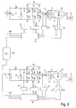
- the invention provides methods and apparatus for adaptively managing the internal combustion engine 300, generator 310, and electric motor 50, 60 for a series type hybrid electric vehicle 10.
- An exemplary embodiment of a series type hybrid electric vehicle 10 according to the invention is controlled so that a generator set 300, 310 of the vehicle 10, including an internal combustion engine 300 connected to a generator 310, reduces the load applied to the internal combustion engine 300 when the internal combustion engine 300 is restarted, lowers the thermal stresses to the internal combustion engine 300 when the engine 300 is turned off and is able to remove excess fuel when turning off the internal combustion engine 300.
- the method further comprises: operating an oil pump to raise the oil pressure of the engine when the engine is off and immediately before the engine is started.
- the pump is integral with the generator.
- the method further comprising: applying an ignition spark in the engine after a predetermined oil pressure is obtained in the internal combustion engine when starting the engine.
- the method further comprises: supplying fuel to the internal combustion engine after an ignition spark has been applied.
- the method further comprises: operating the generator as a motor to start the internal combustion engine; and removing the generator as a motor to start the internal combustion engine after the internal combustion engine has reached a predetermined rotation.
- the method further comprises: raising the temperature of the internal combustion engine before turning on the internal combustion engine.
- the temperature of the internal combustion engine is raised while in an idle mode.
- the method further comprises: determining if the internal combustion engine and generator have exceeded a predetermined energy level while operating in the second and third modes; and lowering an energy level of the internal combustion engine and generator if the predetermined energy level has been exceed.
- the energy level is lowered by reducing a rotation of the internal combustion engine.
- the energy level is lowered by applying a retarder to the internal combustion engine.
- the method further comprises: allowing the engine to idle after a fuel supply has stopped the engine to deplete any unburned fuel and combustible gases from the engine.
- the method further comprises: activating a cooling system to lower the temperature of the internal combustion engine to a predetermined temperature before turning off the engine.
- the method further comprises: shutting off a fuel supplied to the internal combustion engine after the internal combustion engine is below the predetermined temperature level when turning off the engine.
- a series type hybrid electric vehicle 10 includes an internal combustion engine 300 connected to a generator 310, a battery array 30 receiving current at least from the generator 310, at least one electric motor 50, 60 receiving current from the battery array 30, and a controller 200 that selectively operates the engine 300 and generator 310 in various operating modes, including a first mode in which the internal combustion engine 300 and generator 310 are off and the motor 50, 60 propels the vehicle 10 from power stored in the battery array 30, a second mode in which the internal combustion engine 300 and generator 310 are operating without restriction, and a third mode in which the operation of the internal combustion engine 300 and generator 310 are at least partially restricted to limit vehicle discharges.
- the vehicle further comprises: an oil pump selectively operated to raise oil pressure of the engine when the engine is off and immediately before the engine is started.
- the pump is integral with the generator.
- an ignition spark is applied after a predetermined oil pressure is obtained in the internal combustion engine when starting the engine.
- fuel is supplied to the internal combustion engine after an ignition spark has been applied.
- the controller operates the generator as a motor to start the internal combustion engine; and removes the generator as a motor to start the internal combustion engine after the internal combustion engine has reached a predetermined rotation.
- the temperature of the internal combustion engine is raised before turning on the internal combustion engine.
- the temperature of the internal combustion engine is raised while in an idle mode.
- controller determines if the internal combustion engine and generator have exceeded a predetermined energy level while operating in the second and third modes; and lowers an energy level of the internal combustion engine and generator if the predetermined energy level has been exceeded.
- the energy level is lowered by reducing a rotation of the internal combustion engine.
- the energy level is lowered by applying a retarder to the internal combustion engine.
- the controller allows the engine to idle after a fuel supply has stopped the engine to deplete any unburned fuel and combustible gases from the engine.
- the controller activates a cooling system to lower the temperature of the internal combustion engine to a predetermined temperature before turning off the engine.
- the controller turns off the fuel supplied to the internal combustion engine after the internal combustion engine is below the predetermined temperature level when turning off the temperature.
- an exemplary embodiment of a series type hybrid electric vehicle 10 includes a plurality of wheels 11, 12, 13, and 14 and a vehicle chassis 15.
- the wheels 13 and 14 are coupled to electric motors 50 and 60, respectively, through gear boxes 52 and 62, respectively.
- the wheels 13 and 14 are independently mounted to respective suspension components, such as swing arms.
- the wheels 13 and 14 are not coupled together by an axle.
- the wheels 13 and 14 may be coupled together, for example, by an axle.
- the wheels 13 and 14 may be either the front wheels or the rear wheels of the vehicle 10.
- the wheels 11 and 12 are not driven and may be coupled together by an axle.
- the wheels 11 and 12 may also be driven.
- the vehicle 10 is a bus having an occupancy capacity in excess of 100.
- the vehicle may be a bus of a smaller capacity or that the vehicle may be a smaller passenger vehicle, such as a sedan.
- the vehicle may be any size and form currently used or later developed.
- the electric motors 50 and 60 are powered by a battery array 30 and are controlled by motor controllers 51 and 61, respectively.
- the electric motors 50 and 60 are synchronous, permanent magnet DC brushless motors.
- Each electric motor 50 and 60 is rated for 220 Hp and 0-11,000 rpm.
- the maximum combined power output of the electric motors 50 and 60 is thus 440 Hp.
- the permanent magnet DC brushless motors include permanent magnets, such as rare earth magnets, for providing a magnetic field as opposed to AC induction motors which create or induce a magnetic field on the rotating portion of the motor.
- the DC brushless motors are thus inherently more efficient than AC induction motors as no losses occur from inducing the magnetic field.
- the DC brushless motors also have a more useful torque profile, a smaller form factor, and lower weight than AC induction motors.
- the DC brushless motors also require less energy input for an equivalent power output than AC induction motors.
- this invention is not limited to permanent magnet DC brushless motors, and other types of electric motors, such as AC induction motors, can be used.
- the series type hybrid electric vehicle 10 also includes a generator set (genset) 300, 310 including an internal combustion engine 300 and a generator 310 that is driven by the internal combustion engine 300.
- the internal combustion engine 300 may be powered by gasoline, diesel, or compressed natural gas. It should be appreciated, however, that the internal combustion engine 300 may be replaced by a fuel cell, turbine or any other number of alternatives for creating usable electric power.
- the internal combustion engine 300 may be a 2.5 liter Ford LRG-425 engine powered by compressed natural gas.
- the engine 300 is operated to produce 70 Hp. It should be appreciated that the power of the engine 300 may be increased by increasing the RPM of the engine 300 and decreased by decreasing the RPM of the engine 300.
- the performance enhancement factor of the vehicle 10 is 440/70, or at least 6.2.
- Other internal combustion engines can of course be utilized.
- the generator 310 is a DC brushless generator that produces, for example, 240-400 V AC .
- the generator is operated to produce 345 V AC during certain drive modes.
- An output shaft of the internal combustion engine 300 is connected to the generator 310 and the AC voltage of the generator 310 is converted to a DC voltage by a generator controller 320.
- the converted DC voltage charges the battery array 30.
- the battery array may include, for example, 26 deep cycle, lead-acid batteries of 12 volts each connected in series. It should be appreciated, however, that other batteries, such as nickel cadmium, metal hydride or lithium ion, may be used and that any number of batteries can be employed, as space permits.
- the battery array voltage ranges between 240 and 400 V DC .
- An electronic control unit (ECU) 200 includes a programmable logic controller (PLC) 210 and a master control panel (MCP) 220.
- the MCP 220 receives input from various sensors and provides the connection to outputs in the vehicle 10 regarding the information received from the sensors. Some or all of the information is provided to the PLC 210.
- the PLC 210 executes various programs to control, for example, the internal combustion engine 300, the generator 310, the generator controller 320, the electric motors 50 and 60, and the motor controllers 51 and 61, based in part on information received from the MCP 220.
- the vehicle 10 includes a cooling system or cooling systems for the internal combustion engine 300, the generator controller 320, the battery array 30, and the motor controllers 51 and 61.
- the cooling system may be a single system which includes a coolant reservoir, a pump for pumping the coolant through a heat exchanger such as a radiator and a fan for moving air across the heat exchanger or a plurality of cooling systems similarly constructed.
- the ECU 200 controls the cooling systems, including the pumps and the fans, to perform a heat shedding operation in which the heat generated by the engine 300, the controllers 320, 51, and 61, the battery array 30, and various other systems is released to the atmosphere. Any acceptable means and methods for cooling the vehicle components may be utilized.
- the coils of the generator 310 are connected to the generator controller 320.
- the generator controller 320 includes two switching insulated or isolated gate bipolar transistors (IGBT) 330 per phase of the generator 310 and their corresponding diodes.
- the generator controller includes 6 IGBT 330.
- the PLC 210 controls each IGBT 330 of the generator controller 320 to control the conversion of the AC voltage of the generator 310 to the DC voltage for charging the battery array 30.
- the PLC 210 may switch the IGBT 330 off when the SOC of the battery array 30 reaches an upper control limit to stop the conversion of the AC voltage to DC voltage and prevent overcharging of the battery array 30.
- the engine 300 runs continuously during operation of the vehicle 10 and continuously turns the shaft of the generator 310.
- the PLC 210 switches each IGBT 330 on and off via high speed pulse width modulation (PWM) to control charging of the battery array 30.
- PWM pulse width modulation
- the PLC 210 may control the engine 300 by turning the engine 300 on and off to control charging of the battery array 30.
- a control circuit for the electric motors 50 and 60 includes the motor controllers 51 and 61.
- the motor controllers 51 and 61 receive power from the battery array 30 and distribute the power to the electric motors 50 and 60 by switches B1-B6 of pulse width modulation (PWM) inverters 54 and 64.
- PWM pulse width modulation
- the PWM inverters 54 and 64 generate AC current from the DC battery array 30.
- the battery current I B is distributed by the switches B1-B6, for example IGBT, of the PWM inverters 54 and 64 into motor currents I 1 , I 2 , and I 3 for driving the motors 50 and 60.
- the motor controllers 51 and 61 distribute the battery current I B via the switches B1-B6 by factoring feedback from position sensors 53 and 63 and encoders 56 and 66 that determine the timing or pulsing of electromagnets of the motors 50 and 60.
- the pole position sensors 53 and 63 determine the pole positions of the permanent magnets of the motors 50 and 60 and the encoders 56 and 66 determine the phase angle. It should be appreciated that each pair of pole position sensors 53 and 63 and encoders 56 and 66, respectively, may be replaced by a phase position sensor and the phase change frequency may be read to determine the speed of rotation of the electric motors 50 and 60.
- the motor controllers 51 and 61 calculate the motor connector voltages U 12 , U 31 , and U 23 based on the rotary velocity and the known flux value of the motors 50 and 60 between the motor connectors.
- the operation of the inverters 54 and 64 is then determined by the rectified voltages of the diodes of the switches B1-B6 or by the voltage Ui of an intermediate circuit including a capacitor C. If the voltage Ui becomes larger than the battery voltage U B , uncontrolled current may flow to the battery array 30.
- Voltage sensors 55 and 65 determine the voltage Ui and the motor controllers 51 and 61 compare the voltage Ui to the battery voltage U B . If Ui is greater than U B , the motor controllers 51 and 61 activate the switches B1-B6 to cause magnetizing current to flow to the motors 50 and 60 to avoid unnecessary recharging of the battery array 30.
- each motor controller 51 and 61 receives control data from the ECU 200 through a controller area network (CAN).
- CAN controller area network
- the ECU 200 can communicate with the various sensors and the motor controllers 51 and 61 by, for example, DeviceNetTM, an open, global industry standard communication network.
- each motor controller 51 and 61 includes a control unit 101 which includes a field axis current and torque axis current detector 102, a field axis current and torque axis current control unit 103, a field axis current reference control unit 104, a torque axis current reference control unit 105, an rpm calculator 106, a 2/3 phase changer 107, a phase calculator 108 and a PWM control unit 109.
- a control unit 101 which includes a field axis current and torque axis current detector 102, a field axis current and torque axis current control unit 103, a field axis current reference control unit 104, a torque axis current reference control unit 105, an rpm calculator 106, a 2/3 phase changer 107, a phase calculator 108 and a PWM control unit 109.
- the detector 102 calculates the torque axis current I t and the field axis current I f by executing a 3-phase, 2-phase coordinate transfer from the input of (1) current detectors 57 and 67 that measure the 3-phase AC current of the motors 50 and 60 and (2) phase calculator 108 that receives input from the position sensors 53 and 63 and the encoders 56 and 66.
- the field axis current I f is a measure of the current used for winding the motor
- the torque axis current I t is a measure of the back electric current in maintaining the synchronized rotation of the motors 50 and 60 when the rotation of the motors 50 and 60 is reduced.
- the output of detector 102 goes to the field axis current and torque axis current control unit 103.
- the current control unit 103 also receives (1) a field axis current reference value I fref from the field axis current reference control unit 104 and (2) a torque axis current reference value I tref from the torque axis current reference control unit 105.
- the reference control units 104 and 105 determine the current reference values I fref and I tref by comparing a torque reference value T ref (which is determined by the position of an accelerator pedal of the vehicle) with the actual rotational velocity determined by the rpm calculator 106 that receives input from the encoders 56 and 66.
- the 2/3 phase changer 107 receives input from the current control unit 103 and the phase calculator 108, and calculates the 3-phase AC reference values by performing a 2-phase/3-phase coordinate transformation.
- the PWM control unit 109 generates a PWM signal by comparing the 3-phase reference values received from the 2/3 phase changer 107 with a triangular wave signal.
- the PWM control unit 109 communicates this PWM signal to the PWM inverters 54 and 64.
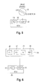
- a master control switch 20 positioned, for example, in an operator area of the vehicle 10, includes an off position, a drive enable position and an engine run position. Any acceptable switch mechanism can be employed.
- the rotary switch 20 in Fig. 5 is merely an example of an acceptable switch.
- the position of the switch 20 is input to the MCP 220.
- the PLC 210 controls the electric motors 50 and 60 to run the vehicle in a driver selected zero emissions mode by drawing power from the battery array 30, i.e., the electric motors 50 and 60 are powered solely by the battery array 30.
- the genset 300, 310 is not operated during the zero emissions mode.
- the range of the vehicle 10 in zero emissions mode is limited as the state of charge (SOC), i.e., the amount of energy stored within a battery, of the battery array 30 will eventually be lowered below a level sufficient to drive the electric motors 50 and 60 to propel the vehicle.
- SOC state of charge
- the ECU 200 instructs the generator 310 to operate as a motor for starting the engine 300.
- the generator 310 receives current from the battery array 30. The current is supplied until the engine 300 reaches a predetermined idling speed and then the current supply is stopped. The engine 300 then drives the generator 310 to charge the battery array 30, as necessary.
- the ECU 200 controls the engine 300 by monitoring the engine speed (rpm) as sensed by a tachometer (not shown) and the fuel mixture as sensed by an oxygen sensor (not shown).
- the ECU 200 may, for example, control a fuel injection amount of the engine 300 and/or the position of a throttle valve of the engine 300.
- the ECU 200 may also monitor engine conditions such as the oil pressure and the coolant temperature as detected by sensors (not shown).
- An automatic zero emission mode is provided by the ECU 200 while in the engine run position when the SOC of the battery array 30 is sufficient or when the sensors of the vehicle 10 sense areas and routes where zero emission modes are required.
- a first driving mode F1 is established by selecting switch 26.
- the first driving mode F1 is established for driving the vehicle at lower speeds under conditions in which the vehicle 10 will start and stop frequently.
- a second driving mode F2 is established by selecting switch 27.
- the second driving mode F2 is established for driving the vehicle at higher speeds and under conditions in which the vehicle is started and stopped less frequently.
- the ECU 200 controls the electric motors 50 and 60 depending on which driving mode is established.
- the maximum power output and rpm of the electric motors 50 and 60 in the second driving mode F2 are higher than the maximum power output and rpm of the motors 50 and 60 in the first driving mode F1.
- the control panel 25 also includes a switch 28 to establish a neutral mode N. In the neutral mode N, the electric motors 50 and 60 are disengaged by the ECU 200. A reverse mode R is established by selecting a switch 29. In the reverse mode R, the electric motors 50 and 60 are controlled to rotate in the opposite direction of the first and second driving modes F1 and F2.
- Power is consumed from the battery array 30 by the electric motors 50 and 60 during acceleration of the vehicle 10 to a cruising speed. As shown in Fig. 7, the vehicle 10 reaches cruising speed at time t 1 which corresponds to a peak power P peak of the electric motors 50 and 60.
- the peak power P peak of the electric motors 50 and 60 is dependent on the driving mode of the vehicle 10 selected by the operator. In the exemplary embodiment of the invention in which the electric motors 50 and 60 are each 220 Hp, the peak power P peak consumed by the electric motors 50 and 60 is 440 Hp.
- the power consumption (traction effort) of the electric motors 50 and 60 during acceleration is represented by the curve below the horizontal axis and the area defined by the curve below the horizontal axis between the times t 0 and t 2 represents the total power consumption of the vehicle 10 during acceleration.
- the ECU 200 controls the motor controllers 51 and 61 to limit the peak power P peak the electric motors 50 and 60 may draw from the battery array 30.
- the traction effort of the electric motors 50 and 60 may be reduced between the time t 1 and a time t 2 , and the power consumption by the electric motors 50 and 60 may also be reduced.
- the cruising speed of the vehicle 10 is maintained between the time t 2 and a time t 3 .
- the genset 300, 310 is operated to produce power P gen higher than the power consumption (traction effort) of the electric motors 50 and 60 necessary to maintain the vehicle's cruising speed.
- the differential in power between the traction effort and the power generated P gen is stored in the battery array 30.
- the power P gen generated by the genset 300, 310 is dependent on the rpm of the engine 300 and a user demand signal sent to the genset 300, 310 that is controlled by the ECU 200.
- the ECU 200 controls the engine 300 to generally maintain the rpm of the engine 300, and the power generated P gen , constant. However, it should be appreciated that the ECU 200 may control the engine 300 to reduce or increase the rpm of the engine 300, and thus the reduce or increase, respectively, the power generated P gen .
- the power generated P gen by the genset 300, 310 may be reduced if the SOC of the battery array 30 approaches an upper control limit at which the battery array 30 may become overcharged.
- the power generated P gen by the genset 300, 310 may be increased if the SOC of the battery array 30 approaches a lower control limit at which the battery array 30 would be unable to drive the electric motors 50 and 60 with enough torque to propel the vehicle 10.
- the power generated P gen is 70 Hp.
- Regenerative braking occurs between the times t 3 and t 4 when the vehicle 10 decelerates after release of the accelerator pedal and when the vehicle 10 travels on a downhill slope at a constant speed.
- the electric motors 50 and 60 function as generators and current is supplied to the battery array 30 by the electric motors 50 and 60.
- the power generated P braking during regenerative braking is stored in the battery array 30.
- the power generated by the genset 300, 310 during maintenance of the cruising speed and the power generated by regenerative braking P braking is represented by the curve above the horizontal axis and the area defined by the curve above the horizontal axis represents the total energy creation and storage of the vehicle 10 during maintenance of the cruising speed and regenerative braking.
- the power P gen of the genset 300, 310 and the regenerative braking power P braking are controlled by the ECU 200 to substantially equal the energy consumption (traction effort) of the electric motors 50 and 60 during acceleration.
- the area defined by the curve below the horizontal axis is equal to the area defined by the curve above the horizontal axis.
- the ECU 200 controls the traction effort of the electric motors 50 and 60 (including the peak power P peak ) and the power generated P gen so that the power generated and the power stored do not exceed the power consumed, and vice versa, so as to maintain the SOC of the battery array 30 within a range of control limits.
- the ECU 200 controls the power generated P gen and the traction effort of the electric motors 50 and 60 so that the ampere hours during energy consumption do not exceed the thermal capacity of the battery array during power creation and storage.
- the genset 300, 310 operates to produce power higher than the power consumption of the electric motors 50 and 60.
- the power output by the genset 300, 310 declines as the SOC of the battery array 30 approaches a high level SOC.
- the battery array 30 is not fully charged, but managed to a SOC level predetermined to maximize the battery life and to accommodate the power requirements of the electric motors 50 and 60.
- the battery array 30 can be maintained at any SOC level less than the maximum SOC level. By keeping the battery array 30 at less than the maximum SOC, the battery array 30 is less likely to experience thermal runaway due to overcharging.
- the MCP 220 can determine the SOC of the battery array 30 over a period of time to determine if there are any trends in the SOC level.
- the trend can be an overall reduction, increase, or maintaining of the SOC of the battery array 30 over a predetermined period of time.
- the MCP 220 can determine an accurate trend because the required energy by the genset 300, 310 does not vary greatly since the genset 300, 310 does not directly drive the vehicle 10.
- the MCP 220 can thus readily determine the trend, and the PLC 210 can adjust the energy requirement of the genset 300, 310 accordingly.
- the vehicle 10 in this exemplary embodiment, has three modes of operation, a zero emissions mode 3, a limited emissions mode 2, and a full emissions mode 1. It should be appreciated that more than three emission modes can be provided, depending, perhaps, on the different environments in which a particular vehicle 10 will be used.
- Zero emission mode 3 refers to the mode of operation of the vehicle 10 in which there are substantially no atmospheric, noise, thermal, or other discharges. It may be desirable for vehicle 10 to operate in the zero emission mode when it is in or adjacent a building or other area with limited air flow or in an area where exhaust gases cause a public health concern.
- one type of environment in which the vehicle 10 may be operated is in a closed route or circuit such as at an airport or a confined shopping area where the vehicle 10 travels the same circuit continuously.
- a closed route or circuit such as at an airport or a confined shopping area where the vehicle 10 travels the same circuit continuously.
- the vehicle 10 may be desirable that the vehicle emit zero emissions when it is in or immediately adjacent a terminal, a rental car facility, a parking garage, etc., i.e., any time the vehicle 10 is in or adjacent a facility with limited air flow or circulation.
- These zero emission environments may not be limited to buildings. It may be desirable for the vehicle 10 to operate at zero emissions even when the vehicle is in an open-air environment if public health is a concern, for example, next to a hospital or other medical facility, in an area where vehicle emissions are of a great concern, etc.
- Vehicle 10 may, of course, be operated in any environment, and its course may vary, i.e., the vehicle 10 may be operated over open roads, without being restricted to a particular circuit or route.
- the intermediate emission mode 2 refers to the mode of operation of the vehicle 10 in which certain or all discharges are restricted or limited.
- the genset 300, 310 does not run at a full operational level in the intermediate emission mode 2.
- One type of environment in which the vehicle 10 may be operated in the intermediate emission mode 2 may be an area bordering a zero emission zone. Also there may be certain environments where certain emissions are prohibited or limited, e.g., a limit on the amount of exhaust gases which are allowed in a particular area for public health reasons, while other discharges (e.g., noise) are not restricted.
- the full emission mode 1 refers to the mode of operation of the vehicle 10 in which the operation of the vehicle 10 is not restricted by any emissions limitations or restrictions.
- the genset 300, 310 can operate at the full operational level without restriction.
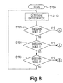
- FIG. 8-11 An exemplary embodiment for controlling the series type hybrid electric vehicle 10 will be explained with reference to Figs. 8-11.
- the control method shown in Figs. 8-11 may be automatically executed at predetermined times or locations during operation of the vehicle 10, or executed manually.
- the control method begins at step S100 and proceeds to step S110 where the MCP 220 determines the emission mode in which vehicle 10 should be operating.
- the emission mode in which the vehicle 10 should be operating may be automatically determined by sensors on the vehicle 10, e.g., a GPS, radio, mechanical trip, mileage counter, etc. mounted on the vehicle 10 which may interact with transmitters along the route traversed by the vehicle 10. It should be appreciated that any automatic means currently available or later developed can be used for the vehicle 10 to determine the location of the vehicle 10, and thus determine what emission mode the vehicle 10 should be in. Also, a visible (e.g., a sign) or an audible signal mechanism could signal to the driver as to the mode the vehicle 10 should be operating in, and the driver could supply this information to the MCP 220.
- a visible e.g., a sign
- an audible signal mechanism could signal to the driver as to the mode the vehicle 10 should be operating in, and the driver could supply this information to the MCP 220.
- step S120 it is determined if the vehicle is in emission mode 1. If the vehicle is in emission mode 1 (S120:Yes), the control method proceeds to step S300 (see Fig. 9). If the vehicle is not in emission mode 1 (S120:No), the control method proceeds to step S130 where it is determined if the vehicle 10 is in emission mode 2. If the vehicle is in emission mode 2 (S130:Yes), the control method also proceeds to step S300.
- step 140 it is determined if the vehicle is in emission mode 3. If the vehicle 10 is not in emission mode 3 (S140:No), the control method returns to step S110 where the MCP 220 again determines what emission mode the vehicle 10 is in. If the vehicle 10 is in emission mode 3 (S140:Yes), the control method proceeds to step S500, which is discussed below.
- step S300 the MCP 220 has determined that the vehicle 10 should be operating in either emission mode 1 or emission mode 2.
- the MCP 220 receives input from a sensor indicating if the internal combustion engine 300 is on. If the internal combustion 300 is on (S330:Yes), the method proceeds to step S400. If the internal combustion engine 300 is off (S300:No), the control method proceeds to step S310 where the PLC 210 instructs the generator 310 to operate as a motor for starting the internal combustion engine 300.
- the PLC 210 also activates an oil pump to increase the oil pressure in the internal combustion engine 300 before it is started by generator 310.
- the pump is an auxiliary oil pump attached to the generator 310.
- the generator 310 also turns on the oil pump.
- an additional pump can also be provided to pump oil into the internal combustion engine 300.
- the additional electrical pump can be a separate pump, which is not attached to the internal combustion engine.
- the control method then proceeds to step S320 where the MCP 220 receives input from a sensor indicating the oil pressure X within the internal combustion engine 300.
- the MCP 220 determines if the oil pressure X is equal to or greater than a predetermined oil pressure X1.
- the predetermined oil pressure X1 is the oil pressure which assures that oil is adequately supplied to the internal combustion engine 300.
- the predetermined oil pressure could be approximately 40 psi.
- other oil pressures may be acceptable, depending on the types of engine and the operating conditions of the engines.
- step S320:No If the MCP 220 determines that the oil pressure X is less than the predetermined oil pressure X1 (S320:No), the control method returns to step S310. If the oil pressure is equal to or greater than the predetermined oil pressure X1, the control method proceeds to step S330 where the PLC 220 instructs the internal combustion engine 300 to start applying an ignition spark. The control method then proceeds to step S340 where the MCP 220 receives input from a sensor indicating whether the spark has been stabilized. If the spark has not been stabilized (S340:No), the control method returns to step S330 where the ignition spark is applied again.
- step S340 If, however, the MCP 220 determines that a stable spark has been achieved, (S340:Yes), the control method proceeds to step S350 where fuel is supplied to the internal combustion engine 300.
- step S360 the MCP 220 receives input from a sensor indicating if the engine 300 has achieved a stable idle.
- a stable idle ignition has been achieved when the MCP 220 determines that the internal combustion engine 300 is able to operate without the use of the generator 310 as a motor. This is normally determined by comparing the rotation of the internal combustion engine 300 with a predetermined rotation, with the predetermined rotation being a rotation at which the engine 300 can sustain operation.
- step 360:No If the rotation of the internal combustion engine 300 is not above the predetermined rotation at step 360 (S360:No), the control method returns to step S350 where more fuel is supplied to the internal combustion engine 300. If, however, the internal combustion engine 300 is above a predetermined rotation (S360:Yes), the control method proceeds to step S370 and the PLC 210 instructs the generator 310 to stop operating as a motor for starting the internal combustion engine 300. At this point, the internal combustion engine 300 is able to operate (rotate) without the assistance of the generator 310.
- this control method and apparatus avoids the application of a large mechanical load to the internal combustion engine 300 upon starting, because a sufficient oil pressure is attained before the spark and fuel are supplied.
- the oil pressure reduces the mechanical load as a sufficient amount of oil creates a smooth transition in restarting the rotation of the internal combustion engine 300.
- the restarting of the genset 300, 310 only has to withstand a relatively low load from the starting of the generator 310 and not a large load from the starting of the internal combustion engine 300.
- step S370 the control method proceeds to step S380 where the MCP 220 receives input from a sensor to determine if the temperature H of the genset 300, 310 is equal to or above a predetermined temperature H1.
- the predetermined temperature H1 is the desired thermal level for operating the genset 300, 310 at full output.
- step S390 the control method proceeds to step S390 where the PLC 210 instructs the genset 300, 310 to move to an idle warm up phase.
- the generator 310 usually reaches an appropriate thermal level to sustain full output faster than the internal combustion engine 300. If the generator reaches an appropriate thermal level before the internal combustion engine 300, the PLC 210 stops the idle-warm up phase for the generator 310 and the generator remains idle, while the engine 200 is still being heated, until the MCP 220 receives input from a sensor associated with the internal combustion engine 300 to indicate that the internal combustion engine has reached an appropriate thermal level to sustain full output.
- the PLC 210 can increase the rate to thermally warm the internal combustion engine 300, as determined by the MCP 220 based on data from sensors, so that both the internal combustion engine 300 and generator 310 reach the appropriate thermal level at substantially the same time.
- the PLC 210 can decrease the rate at which the generator 310 is being heated, based on data from sensors, so that both the internal combustion engine 300 and generator 310 reach the appropriate thermal level at substantially the same time.
- step S400 the MCP 220, as described above, has automatically determined the emission mode in which the vehicle 10 should be operating.
- step S420 the power output by the genset 300, 310 can be maximized.
- the power output by the genset 300, 310 can be maximized as the P gen by the generator 310 can be increased to the current rotation of the internal combustion engine 300 and the rotational speed of the internal combustion engine 300 can be increased to its maximum rotation.
- the genset 300, 310 could go to a normal operation or any other operation to maintain a predetermined SOC of the battery array 30.
- the genset 300, 310 could be desirable for the genset 300, 310 to be operating at full maximum power output when the SOC of the battery array 30 is at a low SOC, if a high power output is required to operate the auxiliary systems of the vehicle, if different routes and/or different times of day vary the average power demands for the battery array 30, or any other situation that would require a rapid charging of the battery array 30.
- step S410 the power output by the genset 300, 310 is minimized.
- the power output of the genset 300, 310 is minimized based on the emission limitations of the environment in which the vehicle 10 is operating.
- the genset 300, 310 can operate to produce power less than the maximum output, but higher than the power consumption of the electric motors 50 and 60, at the same level as the power consumption of the electric motors 50 and 60, or below the power consumption of the electric motors 50 and 60 to reduce the drain on the electrical charge of the battery array 30 to a lower control limit.
- the intermediate mode can have several sub-levels, meeting various emission limitations or restrictions.
- the allowable power output by the genset 300, 310 may vary based on the environment in which vehicle 10 is operating, and may vary at many different levels.
- the PLC 210 when the internal combustion engine 300 is turned on in step S410 and step S420, gradually increases the rotational speed of the internal combustion engine 300.
- the PLC 210 gradually increases the rotational speed, rather than immediately starting the normal operation of the internal combustion engine 300, to further lessen the engine load when starting the internal combustion engine 300.
- step S200 the MCP again receives input from a sensor which measures the energy output E of genset 300, 310, and compares E to a predetermined energy level E1.
- control method proceeds to step S210 where the PLC 210 either reduces the rotation of the internal combustion engine 300, changes the position of the throttle valve of the internal combustion engine 300 to reduce the fuel to engine 300, and/or applies a retarder to slow down the power output of the internal combustion engine 300.
- step S220 the PLC 210 instructs the genset 300, 310 to operate as indicated in step S210 to burn off the excess energy through the internal combustion engine 300.
- excess energy is burned off to reduce the energy level E.
- step S230 the MCP 220 receives input from a sensor to determine if the energy level E is less than the predetermined energy level E1. If the energy level is greater than or equal to the predetermined energy level E1 (5230:Yes), the control method returns to step S210. If the energy level E is less than or equal to the predetermined energy level E1 (S230:No), the control method proceeds to step S250 where the control method ends.
- step S500 the MCP 220 receives input from a sensor to determine if the internal combustion engine 300 is on. If the internal combustion engine is off (S500:Yes), the control method proceeds to step S250, where the control method ends.
- step S510 the PLC 210 switches the internal combustion engine 300 from a power generation mode to an engine idle mode.
- the internal combustion engine 300 stops driving the generator 310.
- the control method then proceeds to step S520 where the PLC 210 activates the cooling system to thermally cool the internal combustion engine 300.
- the control method then proceeds to step S530 where the temperature H of the internal combustion engine 300 is compared to a predetermined temperature H2.
- the predetermined temperature H2 is a predetermined temperature used to prevent thermal shock and a heat soak effect before turning off the internal combustion engine 300.
- the heat soak effect occurs when particular sections of the internal combustion engine 300 are warmer than other sections, with the warmer sections thus warming the entire internal combustion engine.
- step 535 the cooling system remains on until the temperature H of the internal combustion engine 300 is less than the predetermined temperature H2.
- step S540 the PLC 210 shuts off the fuel supplied to the internal combustion engine 300.
- the internal combustion engine 300 remains on after the fuel is shutoff from the internal combustion engine 300 because the remaining fuel and fuel vapors within the internal combustion engine 300 is burned off. Thus, the fuel within the fuel lines and manifolds is removed to prevent backfires and so that unburnt fuel and emissions are emitted.
- step S550 the MCP 220 receives an input from a sensor to determine if the internal combustion engine 300 has stopped. As should be appreciated, the internal combustion engine 300 stops after the fuel and fuel vapors within the internal combustion 300 are burned off. If the MCP 220 determines that the internal combustion engine 300 has stopped (S550:Yes), the control method proceeds to step S560 where the PLC 210 turns off the ignition spark of the internal combustion engine 300.
- step S570 the temperature H of the internal combustion engine, as determined by a sensor, is compared to a predetermined temperature H3.
- the predetermined temperature H3 is lower than the predetermined temperature H2 and is used to uniformly cool the vehicle 10.
- the predetermined temperature H3 is also used to prevent heat from releasing to the atmosphere and to prevent the heat soak after the internal combustion engine 300 has been turned off.
- step S575 the cooling systems remain on.
- the control method When the MCP 220 receives input from the sensors indicating that the temperature H of the internal combustion engine 300 is less than or equal to the predetermined temperature H3, (S570:No), the control method then proceeds to step S580 where the PLC 210 turns off the cooling systems. The control method then proceeds to step S250 where the control method ends.
- the MCP 220 can increase the rotation of the internal combustion engine 300 to increase the thermal output of the internal combustion engine 300.
- the increased thermal output can be used to increase the temperature within the cabin of the vehicle 10.
- the increased thermal output of the internal combustion engine 300 can be used to warm the cabin of the vehicle 10 during cold days or any other time where it is desired to increase the temperature of the cabin of the vehicle 10.
- the internal combustion engine 300 can increase the rotation without increasing the power generated as the IGBT 330 controls the conversion of AC voltage to DC voltage from the generator 310 as described above.
- the vehicle 10 can also use more than one genset 300, 310.
- the additional genset 300, 310 can be used to generate additional energy or thermal output based on the size of the bus, the number of passengers on the bus, different routes used by the vehicle 10, different energy requirements based on the time of day, or any other situation which result in a high energy or thermal output, and thus a high variable genset 300, 310 output.
- the additional genset 300, 310 could be used only when the first genset 300, 310 is not able to maintain the charge of the battery array 30 or thermal output.
- the additional genset 300, 310 can also be used equally with the first genset 300, 310.
- first or additional genset 300, 310 can be smaller and thus have a smaller output than the other genset 300, 310.
- additional genset 300, 310 can be used to supplement the first genset 300, 310.
- this invention covers apparatus and methods to control the vehicle through various emission modes. Moreover, this invention also covers circumstances where a transition period is used before entering the zero emission mode. Thus the transition period for turning off the internal combustion engine can be used before entering the zero emission zone to prevents emission from entering the zero emission zone. Also, as stated, the subject apparatus and method can be utilized by manual activation, as opposed to the use of automatic switch mechanisms.
Landscapes
- Engineering & Computer Science (AREA)
- Chemical & Material Sciences (AREA)
- Combustion & Propulsion (AREA)
- Mechanical Engineering (AREA)
- Transportation (AREA)
- Automation & Control Theory (AREA)
- Life Sciences & Earth Sciences (AREA)
- Sustainable Development (AREA)
- Sustainable Energy (AREA)
- Power Engineering (AREA)
- General Engineering & Computer Science (AREA)
- Human Computer Interaction (AREA)
- Electric Propulsion And Braking For Vehicles (AREA)
- Hybrid Electric Vehicles (AREA)
- Control Of Vehicle Engines Or Engines For Specific Uses (AREA)
Applications Claiming Priority (2)
| Application Number | Priority Date | Filing Date | Title |
|---|---|---|---|
| US764448 | 2001-01-19 | ||
| US09/764,448 US6622804B2 (en) | 2001-01-19 | 2001-01-19 | Hybrid electric vehicle and method of selectively operating the hybrid electric vehicle |
Publications (2)
| Publication Number | Publication Date |
|---|---|
| EP1225073A2 true EP1225073A2 (de) | 2002-07-24 |
| EP1225073A3 EP1225073A3 (de) | 2004-03-17 |
Family
ID=25070759
Family Applications (1)
| Application Number | Title | Priority Date | Filing Date |
|---|---|---|---|
| EP01310176A Withdrawn EP1225073A3 (de) | 2001-01-19 | 2001-12-05 | Hybridfahrzeug und auswählbare Verfahren zu seinem Betrieb |
Country Status (2)
| Country | Link |
|---|---|
| US (4) | US6622804B2 (de) |
| EP (1) | EP1225073A3 (de) |
Cited By (5)
| Publication number | Priority date | Publication date | Assignee | Title |
|---|---|---|---|---|
| WO2006099318A1 (en) * | 2005-03-11 | 2006-09-21 | Solomon Technologies, Inc. | System and method for automating power generation and propulsion management |
| WO2012022455A1 (de) * | 2010-08-16 | 2012-02-23 | Avl List Gmbh | Verfahren zum starten der internen stromerzeugung in einem elektrofahrzeug |
| CN103921739A (zh) * | 2013-01-16 | 2014-07-16 | 通用汽车环球科技运作有限责任公司 | 混合动力电动交通工具中的发热部件的噪声控制 |
| WO2018158571A1 (en) * | 2017-02-28 | 2018-09-07 | Tevva Motors Limited | Range extender |
| WO2022152757A1 (de) * | 2021-01-13 | 2022-07-21 | Obrist Technologies Gmbh | Verfahren zum betreiben eines verbrennungsmotors eines lastkraftfahrzeugs oder omnibusses |
Families Citing this family (125)
| Publication number | Priority date | Publication date | Assignee | Title |
|---|---|---|---|---|
| DE10061659A1 (de) * | 2000-12-11 | 2002-06-20 | Magnet Motor Gmbh | Elektrisches Antriebssystem, insbesondere Fahrzeuge |
| JP3476770B2 (ja) * | 2000-12-18 | 2003-12-10 | 科学技術振興事業団 | 電気自動車の制御装置 |
| US6622804B2 (en) * | 2001-01-19 | 2003-09-23 | Transportation Techniques, Llc. | Hybrid electric vehicle and method of selectively operating the hybrid electric vehicle |
| US6615118B2 (en) * | 2001-03-27 | 2003-09-02 | General Electric Company | Hybrid energy power management system and method |
| US20060005736A1 (en) * | 2001-03-27 | 2006-01-12 | General Electric Company | Hybrid energy off highway vehicle electric power management system and method |
| US7448328B2 (en) * | 2001-03-27 | 2008-11-11 | General Electric Company | Hybrid energy off highway vehicle electric power storage system and method |
| US9151232B2 (en) | 2001-03-27 | 2015-10-06 | General Electric Company | Control system and method |
| US7430967B2 (en) * | 2001-03-27 | 2008-10-07 | General Electric Company | Multimode hybrid energy railway vehicle system and method |
| US7185591B2 (en) * | 2001-03-27 | 2007-03-06 | General Electric Company | Hybrid energy off highway vehicle propulsion circuit |
| US9193268B2 (en) | 2001-03-27 | 2015-11-24 | General Electric Company | Hybrid energy power management system and method |
| JP3767423B2 (ja) * | 2001-06-11 | 2006-04-19 | トヨタ自動車株式会社 | 車両用燃料電池モジュール及び燃料電池自動車 |
| US20050046375A1 (en) * | 2002-07-31 | 2005-03-03 | Maslov Boris A. | Software-based adaptive control system for electric motors and generators |
| US20050052080A1 (en) * | 2002-07-31 | 2005-03-10 | Maslov Boris A. | Adaptive electric car |
| US20040263099A1 (en) * | 2002-07-31 | 2004-12-30 | Maslov Boris A | Electric propulsion system |
| US20050127856A1 (en) * | 2002-07-31 | 2005-06-16 | Wavecrest Laboratories | Low-voltage electric motors |
| JP2004328991A (ja) * | 2003-04-09 | 2004-11-18 | Nissan Motor Co Ltd | 車両の左右輪駆動装置 |
| DE10318738A1 (de) * | 2003-04-25 | 2004-11-11 | Daimlerchrysler Ag | Steuerung eines Elektromotors |
| JP2005023887A (ja) * | 2003-07-04 | 2005-01-27 | Honda Motor Co Ltd | ハイブリッド車両の制御装置 |
| CA2472842C (en) * | 2003-07-22 | 2012-05-29 | Honda Motor Co., Ltd. | Working machine |
| US6876098B1 (en) | 2003-09-25 | 2005-04-05 | The United States Of America As Represented By The Administrator Of The Environmental Protection Agency | Methods of operating a series hybrid vehicle |
| JP3912399B2 (ja) * | 2003-09-29 | 2007-05-09 | 日産自動車株式会社 | 車両用駆動装置 |
| US7224132B2 (en) * | 2004-01-22 | 2007-05-29 | Wavecrest Laboratories, Llc. | Portable range extender operable in automatic and manual modes |
| US7449793B2 (en) | 2004-02-18 | 2008-11-11 | Bluwav Systems, Llc | Portable range extender with autonomous control of starting and stopping operations |
| JP2005297860A (ja) * | 2004-04-14 | 2005-10-27 | Toyota Motor Corp | 車両用電源装置 |
| US7259664B1 (en) * | 2004-06-16 | 2007-08-21 | Chahee Peter Cho | Sensorless fuel level and oil change indicators |
| US7537070B2 (en) * | 2004-06-22 | 2009-05-26 | Bluwav Systems Llc | Autonomous portable range extender |
| US7635932B2 (en) * | 2004-08-18 | 2009-12-22 | Bluwav Systems, Llc | Dynamoelectric machine having heat pipes embedded in stator core |
| US7687945B2 (en) | 2004-09-25 | 2010-03-30 | Bluwav Systems LLC. | Method and system for cooling a motor or motor enclosure |
| EP1794016A1 (de) * | 2004-09-30 | 2007-06-13 | MTD Products Inc. | Hybridnutzfahrzeug |
| US7689331B2 (en) * | 2004-12-01 | 2010-03-30 | Ise Corporation | Method of controlling engine stop-start operation for heavy-duty hybrid-electric and hybrid-hydraulic vehicles |
| US7689330B2 (en) * | 2004-12-01 | 2010-03-30 | Ise Corporation | Method of controlling engine stop-start operation for heavy-duty hybrid-electric and hybrid-hydraulic vehicles |
| US20100145562A1 (en) * | 2004-12-01 | 2010-06-10 | Ise Corporation | Method of Controlling Engine Stop-Start Operation for Heavy-Duty Hybrid-Electric Vehicles |
| US20060137133A1 (en) * | 2004-12-23 | 2006-06-29 | Yik Chi C | Vacuum cleaner |
| US7441616B2 (en) * | 2004-12-27 | 2008-10-28 | Nissan Motor Co., Ltd. | Generated power control system |
| JP2006219082A (ja) * | 2005-02-14 | 2006-08-24 | Hitachi Ltd | 車両用回転電機システム |
| US20060225930A1 (en) * | 2005-04-07 | 2006-10-12 | Schulte Juergen J | Dual axle electric motor drive and method of use |
| US7475747B2 (en) * | 2005-06-03 | 2009-01-13 | Paul J. Plishner | Electric or hybrid vehicle with a spare electric motor power source |
| US7486053B2 (en) * | 2005-06-17 | 2009-02-03 | Hamilton Sundstrand Corporation | Power manager for an electrical power generator |
| US8554877B2 (en) * | 2005-08-19 | 2013-10-08 | Rockwell Automation Technologies, Inc. | Motor drive with integrated server module |
| TWI344258B (en) * | 2005-08-19 | 2011-06-21 | Delta Electronics Inc | Motor driving method and device thereof |
| US20070185969A1 (en) * | 2005-08-19 | 2007-08-09 | Davis Wayne R | Drive with Server |
| WO2007064025A1 (ja) * | 2005-11-30 | 2007-06-07 | Toyota Jidosha Kabushiki Kaisha | 車輪独立駆動式車両の駆動力制御装置 |
| US7479707B2 (en) * | 2006-02-28 | 2009-01-20 | Deere & Company | Method to optimize alternator load capabilities |
| US7543665B2 (en) * | 2006-03-31 | 2009-06-09 | Caterpillar Inc. | Power system |
| US7363995B2 (en) * | 2006-05-01 | 2008-04-29 | American Axle & Manufacturing, Inc. | Overrunning clutch and method of controlling engagement of same |
| US7377343B2 (en) * | 2006-05-01 | 2008-05-27 | American Axle & Manufacturing, Inc. | Centrifugal clutch |
| US7364524B2 (en) * | 2006-05-01 | 2008-04-29 | American Axel & Manufacturing, Inc. | Driveline coupling for electric module |
| US7559390B2 (en) * | 2006-05-01 | 2009-07-14 | American Axle & Manufacturing, Inc. | Electronic all-wheel drive module with overrunning clutch differential |
| US20070251742A1 (en) * | 2006-05-01 | 2007-11-01 | Adams Herbert L Iii | Vehicle with hybrid power train providing part-time all-wheel drive |
| KR100821776B1 (ko) * | 2006-06-09 | 2008-04-11 | 현대자동차주식회사 | 하이브리드 차량에 구비된 메인 배터리의 충방전량 제어방법 |
| EP2620341B1 (de) | 2006-06-26 | 2017-11-29 | GE Hybrid Technologies, LLC | Verfahren, Vorrichtung, Signale und Medien zum Auswählen von Betriebsbedingungen eines Gensatzes |
| US7464780B2 (en) * | 2006-07-20 | 2008-12-16 | Ford Global Technologies, Llc | System and method for recovering regenerative power in a vehicle, and vehicle using the same |
| JP4372775B2 (ja) * | 2006-08-09 | 2009-11-25 | 本田技研工業株式会社 | モータ制御装置 |
| US20080148993A1 (en) * | 2006-12-08 | 2008-06-26 | Tom Mack | Hybrid propulsion system and method |
| WO2009045166A1 (en) * | 2007-10-01 | 2009-04-09 | Singapore Technologies Kinetics Ltd | Radio frequency-based automatic drive switching of hybrid vehicle |
| US8403086B1 (en) * | 2007-10-05 | 2013-03-26 | Leonard Michael Free | System, method and apparatus for supplying supplemental power to an electric vehicle |
| US8198864B2 (en) * | 2007-11-05 | 2012-06-12 | GM Global Technology Operations LLC | Method and system for determining a state of charge of a battery |
| US7928690B2 (en) * | 2007-11-29 | 2011-04-19 | GM Global Technology Operations LLC | Method and system for determining a state of charge of a battery |
| WO2009082808A1 (en) * | 2007-12-28 | 2009-07-09 | Clean Current Power Systems Incorporated | Hybrid electric power system with distributed segmented generator/motor |
| DE102008000579A1 (de) * | 2008-03-10 | 2009-09-17 | Robert Bosch Gmbh | Verfahren und Anordnung zur Ansteuerung eines Fahrzeuges mit Hybridantrieb |
| US8091677B2 (en) * | 2008-03-27 | 2012-01-10 | GM Global Technology Operations LLC | System and method of differentiating rotational speed and torque between wheels of a hybrid vehicle |
| US20110320078A1 (en) * | 2008-06-03 | 2011-12-29 | Mcgill James C | Systems and methods for retrofitting combustible fuel vehicles to a plug-in electric hybrid |
| US7610143B1 (en) | 2008-06-09 | 2009-10-27 | Ford Global Technologies, Llc | Engine autostop and autorestart control |
| US8457727B2 (en) * | 2008-12-19 | 2013-06-04 | Pacesetter, Inc. | Monitoring variation patterns in physiological parameters associated with myocardial instability |
| US8360184B2 (en) * | 2008-07-06 | 2013-01-29 | Paul H. Kydd | Control system for electric hybrid vehicle conversion |
| US8011464B2 (en) * | 2008-07-24 | 2011-09-06 | GM Global Technology Operations LLC | Electric drive system with a selectable one-way clutch |
| EP2933128A1 (de) * | 2008-10-15 | 2015-10-21 | Getrag Ford Transmissions GmbH | Fahrzeug mit antriebsstrang |
| US8430157B1 (en) * | 2009-02-27 | 2013-04-30 | James C. Votaw | Thermal control system |
| US20100280691A1 (en) * | 2009-04-30 | 2010-11-04 | Searete Llc, A Limited Liability Corporation Of The State Of Delaware | Awarding standings to a vehicle based upon one or more fuel utilization characteristics |
| US20100280888A1 (en) * | 2009-04-30 | 2010-11-04 | Searete LLC, a limited libaility corporation of the State of Delaware | Awarding privileges to a vehicle based upon one or more fuel utilization characteristics |
| US20100280885A1 (en) * | 2009-04-30 | 2010-11-04 | Searete Llc, A Limited Liability Corporation Of The State Of Delaware | Awarding privileges to a vehicle based upon one or more fuel utilization characteristics |
| US20100280706A1 (en) * | 2009-04-30 | 2010-11-04 | Searete Llc, A Limited Liability Corporation Of State Of Delaware | Awarding standings to a vehicle based upon one or more fuel utilization characteristics |
| US20100280887A1 (en) * | 2009-04-30 | 2010-11-04 | Searete Llc, A Limited Liability Corporation Of The State Of Delaware | Awarding privileges to a vehicle based upon one or more fuel utilization characteristics |
| US20100280688A1 (en) * | 2009-04-30 | 2010-11-04 | Searete Llc, A Limited Liability Corporation Of The State Of Delaware | Awarding standings to a vehicle based upon one or more fuel utilization characteristics |
| US20100280708A1 (en) * | 2009-04-30 | 2010-11-04 | Searete Llc, A Limited Liability Corporation Of The State Of Delaware | Awarding standings to a vehicle based upon one or more fuel utilization characteristics |
| US20100280692A1 (en) * | 2009-04-30 | 2010-11-04 | Searete Llc, A Limited Liability Corporation Of The State Of Delaware | Awarding standings to a vehicle based upon one or more fuel utilization characteristics |
| US8855907B2 (en) * | 2009-04-30 | 2014-10-07 | Searete Llc | Awarding privileges to a vehicle based upon one or more fuel utilization characteristics |
| US20100280705A1 (en) * | 2009-04-30 | 2010-11-04 | Searete Llc, A Limited Liability Corporation Of The State Of Delaware | Awarding standings to a vehicle based upon one or more fuel utilization characteristics |
| US20100280686A1 (en) * | 2009-04-30 | 2010-11-04 | Searete Llc, A Limited Liability Corporation Of The State Of Delaware | Awarding privileges to a vehicle based upon one or more fuel utilization characteristics |
| US20110106354A1 (en) * | 2009-04-30 | 2011-05-05 | Searete Llc, A Limited Liability Corporation Of The State Of Delaware | Awarding standings to a vehicle based upon one or more fuel utilization characteristics |
| US20110106591A1 (en) * | 2009-04-30 | 2011-05-05 | Searete Llc, A Limited Liability Corporation Of The State Of Delaware | Awarding standings to a vehicle based upon one or more fuel utilization characteristics |
| US20100280690A1 (en) * | 2009-04-30 | 2010-11-04 | Searete Llc, A Limited Liability Corporation Of The State Of Delaware | Awarding standings to a vehicle based upon one or more fuel utilization characteristics |
| US20100280709A1 (en) * | 2009-04-30 | 2010-11-04 | Searete Llc, A Limited Liability Corporation Of The State Of Delaware | Awarding standings to a vehicle based upon one or more fuel utilization characteristics |
| KR20120072372A (ko) | 2009-09-15 | 2012-07-03 | 케이피아이티 커민즈 인포시스템즈 엘티디. | 예측된 주행범위에 근거한 하이브리드 차량에 대한 모터의 지원 |
| WO2011033529A2 (en) | 2009-09-15 | 2011-03-24 | Kpit Cummins Infosystems Ltd. | Motor assistance for a hybrid vehicle based on user input |
| US8423214B2 (en) | 2009-09-15 | 2013-04-16 | Kpit Cummins Infosystems, Ltd. | Motor assistance for a hybrid vehicle |
| JP5914337B2 (ja) | 2009-09-15 | 2016-05-11 | ケーピーアイティ テクノロジーズ リミテッド | 車両をハイブリッド車両に変換する方法 |
| US9187083B2 (en) | 2009-09-16 | 2015-11-17 | Polaris Industries Inc. | System and method for charging an on-board battery of an electric vehicle |
| EP2308708B1 (de) * | 2009-09-16 | 2016-08-17 | swissauto powersport llc | Elektrofahrzeug mit Reichweitenverlängerung |
| US8161720B1 (en) * | 2009-12-03 | 2012-04-24 | Humphrey John L | Grass treatment unit for walk behind greensmower |
| US8364332B2 (en) * | 2010-01-15 | 2013-01-29 | GM Global Technology Operations LLC | Control algorithm for low-voltage circuit in hybrid and conventional vehicles |
| US8104252B1 (en) * | 2010-02-04 | 2012-01-31 | Godley Jr James E | Multi-functional tool heads for lawn mowers and associated method |
| JP6022946B2 (ja) * | 2010-02-26 | 2016-11-09 | セグウェイ・インコーポレイテッド | 車両を制御するための装置及び方法 |
| DE102010003502A1 (de) * | 2010-03-31 | 2011-10-06 | Bayerische Motoren Werke Aktiengesellschaft | Verfahren zum Betrieb eines emissionsfrei betreibbaren Fahrzeugs |
| US8403101B2 (en) * | 2010-09-15 | 2013-03-26 | Deere & Company | User interface for energy sources on a hybrid vehicle |
| DE102011018769A1 (de) * | 2011-04-27 | 2012-10-31 | Daimler Ag | Hybridantriebssteuervorrichtung |
| CA2742011C (en) | 2011-06-02 | 2012-07-17 | Saskatchewan Research Council | Method and system for powering an otto cycle engine using gasoline and compressed natural gas |
| US8935075B2 (en) * | 2011-08-04 | 2015-01-13 | GM Global Technology Operations LLC | Engine start stop inhibit system and method |
| FR2996703B1 (fr) * | 2012-10-10 | 2015-03-20 | Renault Sas | Procede de recuperation d'energie electrique avec lissage de tension sur un reseau electrique embarque |
| US9102334B2 (en) | 2012-10-29 | 2015-08-11 | Deere & Company | Methods and apparatus to control motors |
| US8948946B2 (en) * | 2012-11-29 | 2015-02-03 | GM Global Technology Operations LLC | Hybrid thermal system with device-specific control logic |
| CN103863300B (zh) * | 2012-12-07 | 2016-08-24 | 北汽福田汽车股份有限公司 | 一种增程式电动车的控制方法 |
| US9056556B1 (en) | 2014-02-25 | 2015-06-16 | Elwha Llc | System and method for configuration and management of an energy storage system for a vehicle |
| US9079505B1 (en) | 2014-02-25 | 2015-07-14 | Elwah LLC | System and method for management of a fleet of vehicles having an energy storage system |
| US9878631B2 (en) | 2014-02-25 | 2018-01-30 | Elwha Llc | System and method for predictive control of an energy storage system for a vehicle |
| US9340202B2 (en) | 2014-03-10 | 2016-05-17 | Cummins Inc. | Engine start/stop function management and control architecture |
| US9447764B2 (en) | 2014-07-10 | 2016-09-20 | Cummins Inc. | Internal combustion engine start-stop controls |
| US10300786B2 (en) | 2014-12-19 | 2019-05-28 | Polaris Industries Inc. | Utility vehicle |
| US9862397B2 (en) * | 2015-03-04 | 2018-01-09 | General Electric Company | System and method for controlling a vehicle system to achieve different objectives during a trip |
| JP6160645B2 (ja) * | 2015-03-27 | 2017-07-12 | トヨタ自動車株式会社 | ハイブリッド自動車 |
| CN104879229B (zh) * | 2015-06-02 | 2017-07-04 | 安徽江淮汽车集团股份有限公司 | 一种发动机电子怠速控制方法及控制系统 |
| TWI546682B (zh) | 2015-07-06 | 2016-08-21 | 群暉科技股份有限公司 | 藉助於混和管理路徑來管理一儲存系統之方法與裝置 |
| US9994120B2 (en) * | 2015-09-29 | 2018-06-12 | Ford Global Technologies, Llc | Electrified vehicle method and system for charging during a non-drive cycle |
| US10148202B2 (en) | 2015-10-16 | 2018-12-04 | Kohler Co. | Hybrid device with segmented waveform converter |
| US10778123B2 (en) | 2015-10-16 | 2020-09-15 | Kohler Co. | Synchronous inverter |
| US10063097B2 (en) | 2015-10-16 | 2018-08-28 | Kohler Co. | Segmented waveform converter on controlled field variable speed generator |
| US10148207B2 (en) | 2015-10-16 | 2018-12-04 | Kohler Co. | Segmented waveform converter on controlled field variable speed generator |
| JP2019521028A (ja) | 2016-06-14 | 2019-07-25 | ポラリス インダストリーズ インコーポレーテッド | ハイブリッドユーティリティビークル |
| CN106314072B (zh) * | 2016-08-30 | 2019-04-23 | 浙江吉利动力总成有限公司 | 一种电动汽车增程器热管理系统 |
| KR102370923B1 (ko) * | 2017-09-26 | 2022-03-07 | 현대자동차주식회사 | 공간구분방식 정차제어방법 및 차량 |
| WO2019079000A1 (en) | 2017-10-16 | 2019-04-25 | Massachusetts Institute Of Technology | ACCELERATED OPERATION OF ALCOHOL-FUELED GASOLINE ENGINES |
| US10780770B2 (en) | 2018-10-05 | 2020-09-22 | Polaris Industries Inc. | Hybrid utility vehicle |
| US11370266B2 (en) | 2019-05-16 | 2022-06-28 | Polaris Industries Inc. | Hybrid utility vehicle |
| JP2022013179A (ja) * | 2020-07-03 | 2022-01-18 | トヨタ自動車株式会社 | ハイブリッド車両の制御システム及び制御方法 |
| CN113942491B (zh) * | 2021-11-29 | 2023-10-31 | 中国北方车辆研究所 | 一种串联式混合动力系统及联网混合动力车辆能量管理方法 |
Family Cites Families (74)
| Publication number | Priority date | Publication date | Assignee | Title |
|---|---|---|---|---|
| US4021677A (en) * | 1975-03-03 | 1977-05-03 | Petro-Electric Motors, Ltd. | Hybrid power system |
| FR2377295A1 (fr) | 1977-01-12 | 1978-08-11 | Peugeot | Dispositif de regulation de la source d'energie electrique de bord d'un vehicule electrique hybride |
| DE3433888A1 (de) | 1984-09-14 | 1986-03-27 | Siemens AG, 1000 Berlin und 8000 München | Antriebsanordnung fuer elektrisch angetriebene fahrzeuge |
| US4940114A (en) * | 1989-09-05 | 1990-07-10 | Albrecht Kenneth D | Engine prelubricating system |
| DE4192435C1 (de) | 1990-10-03 | 2002-08-29 | Hitachi Ltd | Steuerung für Elektrofahrzeug |
| IT1241907B (it) | 1990-11-30 | 1994-02-01 | Digitalia S R L In Ragione Del | Metodo e dispositivo per il controllo della trasmissione in veicoli ad alimentazione elettrica |
| JPH05176418A (ja) | 1991-03-25 | 1993-07-13 | Hitachi Ltd | 電気自動車制御装置 |
| IT1246063B (it) * | 1991-04-23 | 1994-11-07 | Iveco Fiat | Gruppo propulsore per un autoveicolo provvisto di mezzi motori azionati per via termica e di mezzi motori azionati per via elettrica |
| EP0596988B1 (de) | 1991-08-01 | 1997-06-04 | Wavedriver Limited | Batteriegespeistes elektrisches Fahrzeug und elektrisches Versorgungssystem |
| JPH05111109A (ja) | 1991-10-08 | 1993-04-30 | Mitsubishi Heavy Ind Ltd | 内燃機関駆動電気式車両の制御方法 |
| US5285862A (en) | 1992-03-16 | 1994-02-15 | Toyota Jidosha Kabushiki Kaisha | Power supply system for hybrid vehicles |
| US5307644A (en) * | 1992-03-26 | 1994-05-03 | Ford Motor Company | Method and electronic device for controlling engine fan |
| JP3551976B2 (ja) * | 1992-04-16 | 2004-08-11 | 株式会社エクォス・リサーチ | ハイブリッド型車両 |
| AU676160B2 (en) | 1992-04-28 | 1997-03-06 | Dynamic Controls Limited | Control means for electrically driven vehicles |
| DE69327072T2 (de) | 1992-05-15 | 2000-07-20 | Mitsubishi Motors Corp | Verfahren zum Betrieb eines hybriden Fahrzeugs |
| WO1994007301A1 (de) | 1992-09-24 | 1994-03-31 | Siemens Aktiengesellschaft | Verfahren und vorrichtung zur regelung eines umrichtergespeisten permanenterregten synchronmotors |
| US5318142A (en) | 1992-11-05 | 1994-06-07 | Ford Motor Company | Hybrid drive system |
| US5291960A (en) * | 1992-11-30 | 1994-03-08 | Ford Motor Company | Hybrid electric vehicle regenerative braking energy recovery system |
| JP3092403B2 (ja) * | 1993-09-06 | 2000-09-25 | 三菱自動車工業株式会社 | ハイブリッド電気自動車 |
| US5512022A (en) | 1993-10-26 | 1996-04-30 | Suzuki; Naruhito | Motor mechanism |
| JP3379613B2 (ja) | 1994-06-30 | 2003-02-24 | 東芝ライテック株式会社 | 蛍光ランプ装置および照明装置 |
| JP3178503B2 (ja) | 1994-07-01 | 2001-06-18 | 株式会社デンソー | ハイブリッド自動車の制御装置 |
| DE19502501C2 (de) | 1995-01-27 | 2000-11-30 | Mannesmann Sachs Ag | Sicherheitsschaltung für Kfz mit Elektrotraktion |
| JPH08289407A (ja) | 1995-02-13 | 1996-11-01 | Nippon Soken Inc | ハイブリッド車の発電制御装置 |
| US5589743A (en) | 1995-03-03 | 1996-12-31 | General Electric Company | Integrated cranking inverter and boost converter for a series hybrid drive system |
| US6116363A (en) * | 1995-05-31 | 2000-09-12 | Frank Transportation Technology, Llc | Fuel consumption control for charge depletion hybrid electric vehicles |
| US5704440A (en) * | 1995-05-31 | 1998-01-06 | New York Institute Of Technology | Energy distribution method for hydrid electric vehicle |
| US5739664A (en) | 1996-02-05 | 1998-04-14 | Ford Global Technologies, Inc. | Induction motor drive controller |
| JP3328509B2 (ja) | 1996-05-29 | 2002-09-24 | 株式会社日立製作所 | 電気車用駆動システム |
| DE69722753D1 (de) | 1996-07-09 | 2003-07-17 | Solaria Res Entpr Ltd | Regelungssystem für einen fremderregten gleichstrommotor |
| JP3097594B2 (ja) * | 1996-07-26 | 2000-10-10 | トヨタ自動車株式会社 | 動力出力装置 |
| CA2182630C (en) | 1996-08-02 | 2003-02-11 | Piotr Drozdz | A control system for a hybrid vehicle |
| DE19633194C2 (de) * | 1996-08-17 | 1998-09-17 | Daimler Benz Ag | Serieller Hybridantrieb, insbesondere für ein Kraftfahrzeug |
| US6073712A (en) | 1997-01-23 | 2000-06-13 | Chrysler Corporation | Method of power output level control for a hybrid power train system |
| US5804935A (en) | 1997-02-06 | 1998-09-08 | Radev; Vladimir | Drive system for electric vehicles |
| JP3164007B2 (ja) * | 1997-02-14 | 2001-05-08 | トヨタ自動車株式会社 | 内燃機関のバルブタイミング調整装置 |
| US5878830A (en) | 1997-02-18 | 1999-03-09 | Meritor Heavy Vehicle Systems, Llc. | Space saving mounting for electrically driven vehicle wheels |
| US5924504A (en) | 1997-02-18 | 1999-07-20 | Meritor Heavy Vehicle Systems, Llc | Suspension drive unit assembly for an electrically driven vehicle |
| JP3775012B2 (ja) * | 1997-08-29 | 2006-05-17 | アイシン・エィ・ダブリュ株式会社 | 車両用ハイブリッド駆動装置 |
| EP0906847A3 (de) | 1997-10-02 | 2001-08-08 | Siemens Aktiengesellschaft | Antriebsvorrichtung für ein Elektrofahrzeug |
| US6367570B1 (en) * | 1997-10-17 | 2002-04-09 | Electromotive Inc. | Hybrid electric vehicle with electric motor providing strategic power assist to load balance internal combustion engine |
| JP3536634B2 (ja) * | 1997-12-25 | 2004-06-14 | 日産自動車株式会社 | ハイブリッド車両の制御装置 |
| JP3533958B2 (ja) | 1997-12-25 | 2004-06-07 | 日産自動車株式会社 | ハイブリッド車両の制御装置 |
| JP3381613B2 (ja) * | 1998-03-20 | 2003-03-04 | 日産自動車株式会社 | ハイブリッド車両の駆動制御装置 |
| JP3425730B2 (ja) * | 1998-03-31 | 2003-07-14 | 本田技研工業株式会社 | ハイブリッド車両の制御装置 |
| US5905349A (en) | 1998-04-23 | 1999-05-18 | Ford Motor Company | Method of controlling electric motor torque in an electric vehicle |
| DE19826551C1 (de) | 1998-06-15 | 1999-11-18 | Siemens Ag | Steuerungssystem für ein aus mindestens einem Energiespeicher und einer Energiequelle bestehendes Hybridsystem |
| US6464026B1 (en) * | 1998-10-09 | 2002-10-15 | John Horsley | Control system for parallel hybrid vehicle |
| JP3719339B2 (ja) * | 1998-11-09 | 2005-11-24 | 日産自動車株式会社 | 内燃機関の可変動弁制御装置 |
| JP3300295B2 (ja) | 1998-12-07 | 2002-07-08 | 本田技研工業株式会社 | ハイブリッド車両の制御装置 |
| JP3803205B2 (ja) * | 1998-12-28 | 2006-08-02 | 本田技研工業株式会社 | ハイブリッド自動車 |
| US6142757A (en) * | 1999-03-23 | 2000-11-07 | Emerson Electric Co. | Integral oil pump |
| JP3494074B2 (ja) | 1999-05-18 | 2004-02-03 | トヨタ自動車株式会社 | 動力出力装置およびその制御方法、並びにハイブリッド車両 |
| JP2001193661A (ja) * | 1999-06-08 | 2001-07-17 | Denso Corp | 作動油供給システムおよびその制御方法 |
| JP3542932B2 (ja) | 1999-08-04 | 2004-07-14 | 本田技研工業株式会社 | ハイブリッド車両の減速回生/充電の許可判定方法および装置 |
| JP3880752B2 (ja) | 1999-08-06 | 2007-02-14 | 本田技研工業株式会社 | エンジン自動始動停止制御装置 |
| JP3566151B2 (ja) | 1999-10-04 | 2004-09-15 | 本田技研工業株式会社 | ハイブリッド自動車のモータ制御装置 |
| JP3352987B2 (ja) | 1999-12-20 | 2002-12-03 | 本田技研工業株式会社 | ハイブリッド車両の制御装置 |
| US6242873B1 (en) | 2000-01-31 | 2001-06-05 | Azure Dynamics Inc. | Method and apparatus for adaptive hybrid vehicle control |
| JP3912475B2 (ja) * | 2000-02-24 | 2007-05-09 | 三菱ふそうトラック・バス株式会社 | ハイブリッド電気自動車の発電制御装置 |
| JP2001268719A (ja) * | 2000-03-23 | 2001-09-28 | Toyota Motor Corp | ハイブリッド車両のバッテリ充電制御装置 |
| JP3909641B2 (ja) * | 2000-04-05 | 2007-04-25 | スズキ株式会社 | ハイブリッド車両の制御装置 |
| US6405818B1 (en) | 2000-04-11 | 2002-06-18 | Ford Global Technologies, Inc. | Hybrid electric vehicle with limited operation strategy |
| US6356042B1 (en) * | 2000-07-05 | 2002-03-12 | Gurinder S. Kahlon | Engine shut off system for a hybrid electric vehicle |
| US6333620B1 (en) * | 2000-09-15 | 2001-12-25 | Transportation Techniques Llc | Method and apparatus for adaptively controlling a state of charge of a battery array of a series type hybrid electric vehicle |
| JP3832237B2 (ja) | 2000-09-22 | 2006-10-11 | 日産自動車株式会社 | ハイブリッド車の制御装置 |
| US6441574B1 (en) | 2000-10-27 | 2002-08-27 | Ford Motor Company | Energy control strategy for a hybrid electric vehicle |
| US6449537B1 (en) | 2000-10-27 | 2002-09-10 | Ford Motor Company | Energy control strategy for a hybrid electric vehicle |
| US6543565B1 (en) | 2000-11-10 | 2003-04-08 | Ford Motor Company | Method and system for collecting regenerative braking energy in a parallel hybrid electric vehicle |
| US6573675B2 (en) * | 2000-12-27 | 2003-06-03 | Transportation Techniques Llc | Method and apparatus for adaptive energy control of hybrid electric vehicle propulsion |
| US6483198B2 (en) * | 2001-01-19 | 2002-11-19 | Transportation Techniques Llc | Hybrid electric vehicle having a selective zero emission mode, and method of selectively operating the zero emission mode |
| US6622804B2 (en) * | 2001-01-19 | 2003-09-23 | Transportation Techniques, Llc. | Hybrid electric vehicle and method of selectively operating the hybrid electric vehicle |
| US6487477B1 (en) * | 2001-05-09 | 2002-11-26 | Ford Global Technologies, Inc. | Strategy to use an on-board navigation system for electric and hybrid electric vehicle energy management |
| JP3910122B2 (ja) * | 2002-08-30 | 2007-04-25 | ジヤトコ株式会社 | 車両用変速システムのエンジン出力トルク制御装置 |
-
2001
- 2001-01-19 US US09/764,448 patent/US6622804B2/en not_active Expired - Lifetime
- 2001-12-05 EP EP01310176A patent/EP1225073A3/de not_active Withdrawn
-
2003
- 2003-07-18 US US10/621,606 patent/US6877576B2/en not_active Expired - Lifetime
- 2003-07-18 US US10/621,410 patent/US7017542B2/en not_active Expired - Lifetime
-
2005
- 2005-12-08 US US11/296,420 patent/US7121234B2/en not_active Expired - Fee Related
Non-Patent Citations (1)
| Title |
|---|
| None |
Cited By (10)
| Publication number | Priority date | Publication date | Assignee | Title |
|---|---|---|---|---|
| WO2006099318A1 (en) * | 2005-03-11 | 2006-09-21 | Solomon Technologies, Inc. | System and method for automating power generation and propulsion management |
| WO2012022455A1 (de) * | 2010-08-16 | 2012-02-23 | Avl List Gmbh | Verfahren zum starten der internen stromerzeugung in einem elektrofahrzeug |
| CN103153684A (zh) * | 2010-08-16 | 2013-06-12 | 李斯特内燃机及测试设备公司 | 用于在电动汽车中启动内部发电机的方法 |
| CN103153684B (zh) * | 2010-08-16 | 2016-01-20 | 李斯特内燃机及测试设备公司 | 用于在电动汽车中启动内部发电机的方法 |
| CN103921739A (zh) * | 2013-01-16 | 2014-07-16 | 通用汽车环球科技运作有限责任公司 | 混合动力电动交通工具中的发热部件的噪声控制 |
| CN103921739B (zh) * | 2013-01-16 | 2016-08-17 | 通用汽车环球科技运作有限责任公司 | 混合动力电动交通工具中的发热部件的噪声控制 |
| WO2018158571A1 (en) * | 2017-02-28 | 2018-09-07 | Tevva Motors Limited | Range extender |
| GB2562438A (en) * | 2017-02-28 | 2018-11-14 | Tevva Motors Ltd | Range Extender |
| GB2562438B (en) * | 2017-02-28 | 2019-07-10 | Tevva Motors Ltd | Range Extender |
| WO2022152757A1 (de) * | 2021-01-13 | 2022-07-21 | Obrist Technologies Gmbh | Verfahren zum betreiben eines verbrennungsmotors eines lastkraftfahrzeugs oder omnibusses |
Also Published As
| Publication number | Publication date |
|---|---|
| EP1225073A3 (de) | 2004-03-17 |
| US20040026142A1 (en) | 2004-02-12 |
| US7017542B2 (en) | 2006-03-28 |
| US20060106524A1 (en) | 2006-05-18 |
| US20040007404A1 (en) | 2004-01-15 |
| US7121234B2 (en) | 2006-10-17 |
| US6877576B2 (en) | 2005-04-12 |
| US20020096375A1 (en) | 2002-07-25 |
| US6622804B2 (en) | 2003-09-23 |
Similar Documents
| Publication | Publication Date | Title |
|---|---|---|
| US6622804B2 (en) | Hybrid electric vehicle and method of selectively operating the hybrid electric vehicle | |
| US6483198B2 (en) | Hybrid electric vehicle having a selective zero emission mode, and method of selectively operating the zero emission mode | |
| US6333620B1 (en) | Method and apparatus for adaptively controlling a state of charge of a battery array of a series type hybrid electric vehicle | |
| US6573675B2 (en) | Method and apparatus for adaptive energy control of hybrid electric vehicle propulsion | |
| US7122979B2 (en) | Method and apparatus for selective operation of a hybrid electric vehicle in various driving modes | |
| CN108688642B (zh) | 自主车辆恒定速度控制系统 | |
| US5973460A (en) | Power output apparatus and method of controlling the same | |
| US10160307B2 (en) | System and method for controlling motor temperature for green car | |
| US6098734A (en) | Hybrid powered automobile with controller | |
| US10618399B2 (en) | Front-engine extended range electric passenger vehicle | |
| EP2808213A1 (de) | Hybridfahrzeugverwaltungssystem, hybridfahrzeugsteuerungsvorrichtung und hybridfahrzeugsteuerungsverfahren | |
| US10723344B2 (en) | Hybrid vehicle and control device mounted thereon | |
| CN108068796B (zh) | 控制车辆的驱动电动机的系统和方法 | |
| US10583827B2 (en) | Hybrid vehicle and control device mounted thereon | |
| US20190168741A1 (en) | Hybrid vehicle and control device mounted thereon | |
| WO2009067810A1 (en) | Apparatus, method and memory for improving the performance and charging of hybrid electric vehicles | |
| JP2973657B2 (ja) | シリーズハイブリッド車における電力配分装置 | |
| JP2004076687A (ja) | 排気/電動過給式ハイブリッド車 | |
| Schier et al. | Methodical approach for designing electric propulsion systems containing two motors | |
| Krishna et al. | Plug in Hybrid Vehicle-A Simulation Study | |
| Čeřovský et al. | Power electronics in automotive hybrid drives | |
| Gebrehiwot et al. | Range extenders for electric vehicles | |
| CN106476637A (zh) | 深混混合动力汽车、电源、驱动控制系统及控制方法 | |
| Gugale et al. | Rule based energy management strategy for a parallel mild hybrid electric vehicle | |
| Jefferies et al. | The petro-electric drive train |
Legal Events
| Date | Code | Title | Description |
|---|---|---|---|
| PUAI | Public reference made under article 153(3) epc to a published international application that has entered the european phase |
Free format text: ORIGINAL CODE: 0009012 |
|
| AK | Designated contracting states |
Kind code of ref document: A2 Designated state(s): AT BE CH CY DE DK ES FI FR GB GR IE IT LI LU MC NL PT SE TR |
|
| AX | Request for extension of the european patent |
Free format text: AL;LT;LV;MK;RO;SI |
|
| PUAL | Search report despatched |
Free format text: ORIGINAL CODE: 0009013 |
|
| AK | Designated contracting states |
Kind code of ref document: A3 Designated state(s): AT BE CH CY DE DK ES FI FR GB GR IE IT LI LU MC NL PT SE TR |
|
| AX | Request for extension of the european patent |
Extension state: AL LT LV MK RO SI |
|
| 17P | Request for examination filed |
Effective date: 20040906 |
|
| AKX | Designation fees paid |
Designated state(s): AT BE CH CY DE DK ES FI FR GB GR IE IT LI LU MC NL PT SE TR |
|
| 17Q | First examination report despatched |
Effective date: 20050124 |
|
| STAA | Information on the status of an ep patent application or granted ep patent |
Free format text: STATUS: THE APPLICATION IS DEEMED TO BE WITHDRAWN |
|
| 18D | Application deemed to be withdrawn |
Effective date: 20050805 |