EP1222677B1 - Source ionique a flux electronique - Google Patents
Source ionique a flux electronique Download PDFInfo
- Publication number
- EP1222677B1 EP1222677B1 EP00982966A EP00982966A EP1222677B1 EP 1222677 B1 EP1222677 B1 EP 1222677B1 EP 00982966 A EP00982966 A EP 00982966A EP 00982966 A EP00982966 A EP 00982966A EP 1222677 B1 EP1222677 B1 EP 1222677B1
- Authority
- EP
- European Patent Office
- Prior art keywords
- electron
- electron beam
- ion source
- vacuum
- axis
- Prior art date
- Legal status (The legal status is an assumption and is not a legal conclusion. Google has not performed a legal analysis and makes no representation as to the accuracy of the status listed.)
- Expired - Lifetime
Links
Images


Classifications
-
- H—ELECTRICITY
- H01—ELECTRIC ELEMENTS
- H01J—ELECTRIC DISCHARGE TUBES OR DISCHARGE LAMPS
- H01J27/00—Ion beam tubes
- H01J27/02—Ion sources; Ion guns
- H01J27/16—Ion sources; Ion guns using high-frequency excitation, e.g. microwave excitation
- H01J27/18—Ion sources; Ion guns using high-frequency excitation, e.g. microwave excitation with an applied axial magnetic field
Definitions
- the invention relates to an electron impact ion source according to the preamble of claim 1.
- the electron impact ion source allows the generation of highly charged ions, their extraction, serves as a source of UV, VUV, infrared rays and highly charged ions of characteristic X-rays.
- EBIT E Lectron B eam I on T rap
- MA Levine RE Marrs
- JR Henderson DA Knapp
- MB Schneider Physica Scripta, T22 (1988) 157 in which multiply-charged ions are generated in an axisymmetric high-density electron beam which is accelerated by a system of consecutive drift tubes under ultra-high vacuum conditions and focused by superconductive home-coil coils.
- the system consists of an electron gun, several cylindrical drift tubes, an electron collector, an extractor, a focusing magnet system and a system for creating ultra-high vacuum conditions in the plant.
- the electron beam generates in the middle part of the system an ion trap, which holds the ions in the radial direction by their space charge forces.
- the obtained highly charged ions can be extracted from the ion trap along the trap axis by lowering the trap potential at the last drift tube.
- characteristic x-ray radiation and other long-wave electromagnetic radiation emitted by the stored ions are emitted in the meridian plane of the magnet system and perpendicular to the source axis.
- the maximum achievable ionic charge is a function of the ionization factor j ⁇ , ie the product of the electron current density j and the ion residence time ⁇ in the electron beam of the trap.
- the process limiting the achievement of highest charge states is essentially the process of transhipment of multiple charged ions to residual gas atoms. Therefore, devices that generate highly charged ions based on the described method must be Forming a high-density electron beam under ultra-high vacuum conditions.
- cryogenic technology in connection with superconducting technology is used in EBIT plants.
- Superconducting Helmholtz coils with magnetic field inductions of 3T to 5T are used here to focus the electron beam over the length of the ion trap, which does not exceed 25 mm in known systems.
- the current density of the electron beam over the case length is 2,000-5,000 A / cm 2 for a total length of the electron-optical system (cathode-electron collector) of more than 30 cm.
- the cryogenic system fulfills in addition to the Kryostat ist the superconducting Helmholtz coils at a temperature of 4.2 K, the function of an efficient cryopump in the range of the ion trap to create a vacuum of ⁇ 10 -11 to 10 -12 Torr.
- MTCRO-EBIT As in H. Khodja, JP Briand; Physica Scripta, T71 (1997) 113 described.
- the basic idea of the design of these plants is that a compact, industrially manufactured klystron is used to generate an ion trap of the EBIT type.
- the focusing magnetic field which limits the radial dimensions of the electron beam in the region of the ion trap, is generated by two C-shaped permanent magnets, which provide a magnetic induction of strength 0.25 T.
- the original cathode of the klystron with a maximum emissivity of 2.5 A / cm 2 is used.
- the ultra-high vacuum in the system is achieved after heating at 300 ° C according to standard technology with the combination of a turbomolecular and an ion getter pump.
- Ar 16+ ions were detected after an ionization time of 1.2 s, ie an ionization factor of about 1.10 20 cm -2 was achieved, which corresponds to an electron current density of 14 A / cm 2 .
- This system has a low electron current density in the beam (100 times less than for superconducting EBIT). Associated with this is a limitation to relatively low Tonenladungszupoint as Ar 16+.
- the unsuitable choice of a cathode with comparatively low emissivity and, associated therewith, the use of an electron gun with a relatively large electrostatic divergence of the electron beam is another decisive disadvantage.
- a minimum value for the aberrations is possible in the case of paraxial and laminar flows, ie for an electron gun with minimal divergence (compression) of the electron beam and thus for a maximally efficient cathode, ie for a cathode with maximum emission density.
- the object of the invention is to provide an effective electron impact ion source (WEBIT) without any cryogenic components and without superconducting technique for the preservation highly charged ions, X-ray and VUV spectroscopy on these ions and the extraction of the highly charged ions from the trap for a variety of scientific, technological and technical applications.
- WEBIT electron impact ion source
- the object is achieved in conjunction with the features mentioned in the preamble of claim 1, characterized in that the device for axially symmetrical focusing of the electron beam consists of at least two oppositely radially magnetized ring structures and each of the ring structures surrounds the electron beam, and two oppositely radially magnetized ring structures are connected to form a uniform magnetic system by magnetic conductors, wherein the closing magnetic field the residence area of the ions in the trap penetrates.
- magnetized permanent magnet blocks are assembled into ring structures and enclosed by magnetic conductors of soft magnetic material, so that there is a radial magnetization.
- magnetized permanent magnet blocks cuboid of hard magnetic materials such as Sm 5 Co or NdFeB, which can be produced efficiently the ring structures.
- the opening and closing of the ion trap advantageously consists of a three-part drift tube mounted on a high-voltage insulator. At the middle part of a controllable acceleration potential and the two outer parts is set an adjustable trap potential.
- the central part of the drift tube is provided with a number of slots or other suitable openings running along the axial electron beam, which allow efficient pumping in the region of the ion trap.
- a vacuum recipient is provided with four flanges in which two opposing flanges form a first axis and two further flanges form a second axis, with first and second axes intersecting on the first axis electron gun, drift tube, electron collector and extractor are arranged in this order, and along the second axis to a flange, a high-voltage bushing for positioning the drift tube in the course of the first axis and at the other flange, a vacuum pump is connected.
- Other solutions with more or less flanges are possible.
- the magnetic conductors advantageously pierce the vacuum recipient parallel to the first axis on both sides of the second axis and form a seating for the rings there.
- the protruding into the vacuum recipient part of the magnetic conductor is angled in a 1-shape and magnetically short-circuited with the drift tube.
- the advantage of the invention is that highly charged ions can be generated efficiently without cryogenic technology.
- FIG. 1 the invention is shown schematically.
- electron gun 3 with cathode 14 three drift tubes 4 , 15 , 4 , an electron collector 5 , and an extractor 6 are arranged in this order.
- the ion trap is formed by the three drift tubes 4 , 15 , 4 .
- Two counter-radially magnetized ring structures 2 enclose the axis 16 at the input and output of the drift tube structure 4 , 15 and thus the producible electron beam.
- the ring structures 2 contain a number of permanent magnet blocks 8 with which the ring structures 2 receive a radial magnetization.
- inner pole shoes are arranged with which closed magnetic circuits 13 are generated via the drift tube structure 4 , 15 .
- an electron impact ion source consisting of a vacuum recipient 1 , a magnetically focussing system 2 , an electron gun 3 , a drift tube structure 4 , 15 mounted on a high voltage insulator, which under certain circumstances may dispense with the high voltage insulator, an electron collector 5 and an extractor 6 exists.
- a vacuum recipient 1 pole pieces 7 of soft magnetic material for field formation in the region of the ion trap are mounted in its interior.
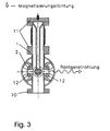
- the magnetic field is generated by two ring structures 2 of radially magnetized permanent magnet blocks 8 , which, as shown in FIG Fig. 4 are connected to each other by a system of magnetic conductors 7.9 made of soft magnetic material.
- the individual magnetic elements have the shape of simple cuboid, making it possible without difficulty to use modern hard magnetic materials such as Sm 5 Co or NdFeB.
- the ring structures 2 are located outside of the vacuum recipient 1 and can therefore be dismantled during the time of a heating of the device to obtain ultrahigh vacuums. This special feature of the system makes it possible to dispense with temperature limitations in the annealing process because of the relatively low Curie temperatures of modern hard magnetic materials.
- Flanges 10 for the coupling of the system to the system for generating the required vacuum, the isolated vacuum feedthrough 11 to the drift tubes 4,15 and spectroscopic window 12 for the spectroscopy of the characteristic X-rays or VUV radiation, which is formed in the ion-charged electron beam are in the meridian plane of the device. Therefore, the distances between the location of the formation of the characteristic X-ray radiation or the VUV radiation and possible detectors and the distances to the required vacuum pumps can be minimized. This has the consequence that the system has a maximum large solid angle (and thus maximum detection efficiency) in the registration of the characteristic X-ray radiation or VUV radiation and a maximum pumping speed at the vacuum generation.
- the electron gun 3 differs by its geometric dimensions, in particular by the cathode diameter, which is chosen with the aim to reduce the angular divergence of the electron beam and to achieve a paraxial current.
- the compression level of the electron beam in the electron gun 3 is 4 (ie, the ratio of the cathode radius to the radius of the electron beam in the cross-over is 2).
- the values given were obtained for a Brillouin field value of 250 mT and for a cathode emissivity of 25 A / cm 2 .
- Table I shows the ions obtained with the electron impact ion source of the present invention.
- Table I element ordinal Maximum state of charge * argon 18 17 krypton 36 34 xenon 54 44 cerium 58 48 iridium 77 67 mercury 80 70 * ) confirmed by X-ray spectroscopy at an electron energy of 15 keV
Landscapes
- Chemical & Material Sciences (AREA)
- Engineering & Computer Science (AREA)
- Combustion & Propulsion (AREA)
- Electron Sources, Ion Sources (AREA)
- Dental Preparations (AREA)
- Luminescent Compositions (AREA)
- Other Investigation Or Analysis Of Materials By Electrical Means (AREA)
- Particle Accelerators (AREA)
Claims (8)
- Source ionique à flux électronique pour générer des ions fortement chargés, composée- d'un canon à électrons avec une cathode et une anode pour générer et accélérer des électrons, la cathode présentant une émissivité ≥ 25 A/cm2,- d'un dispositif pour focaliser le faisceau d'électrons de manière axialement symétrique,- de moyens pour introduire des substances ionisables dans un piège à ions pouvant être ouvert et fermé dans la région du faisceau d'électrons focalisé de manière axialement symétrique,- d'un dispositif pour détruire les électrons après la traversée du piège à ions,- ainsi que d'un dispositif servant à produire un vide autour du faisceau d'électrons focalisé de manière axialement symétrique et du piège à ions qui s'y trouve, un vide de 10-7 à 10-11 Torr étant réglable dans la région de séjour des ions pendant le fonctionnement de la source ionique à flux électronique,caractérisée en ce que- le dispositif pour focaliser le faisceau d'électrons de manière axialement symétrique est composé d'au moins deux structures annulaires (2) magnétisées radialement en sens contraires et chacune des structures annulaires (2) entoure le faisceau d'électrons,- deux structures annulaires (2) magnétisées radialement en sens contraires sont chaque fois reliées à un système magnétique unitaire par des conducteurs magnétiques (7,9), le champ magnétique qui se ferme traversant la région de séjour des ions dans le piège à ions.
- Source ionique à flux électronique selon la revendication 1, caractérisée en ce que les structures annulaires (2) magnétisées radialement sont formées par des blocs d'aimants permanents (8) et reliées par les conducteurs magnétiques (7,9) à un circuit magnétique (13), les conducteurs magnétiques (7,9) étant formés d'un matériau magnétique doux.
- Source ionique à flux électronique selon la revendication 2, caractérisée en ce que les blocs d'aimants permanents (8) magnétisés sont composés de parallélépipèdes en matériaux magnétiques durs tels que Sm5Co ou NdFeB.
- Source ionique à flux électronique selon l'une des revendications 1 à 3, caractérisée en ce que les structures annulaires (2) magnétisées radialement sont disposées de manière amovible à l'extérieur du dispositif servant à produire un vide.
- Source ionique à flux électronique selon l'une des revendications 1 à 5, caractérisée en ce que le piège à ions pouvant être ouvert et fermé est composé d'un tube de dérive en trois parties (4, 15, 4) monté sur un isolateur haute tension, un potentiel d'accélération commandable pouvant être appliqué à la partie centrale (15) et un potentiel de piège réglable aux deux parties extérieures.
- Source ionique à flux électronique selon la revendication 5, caractérisée en ce que le tube de dérive central (15) est pourvu d'une pluralité de trous oblongs s'étendant le long du faisceau d'électrons central pour produire un vide dans la zone d'ionisation.
- Source ionique à flux électronique selon l'une des revendications 1 à 6, caractérisée en ce qu'il est prévu un récipient à vide (1) avec quatre brides (10), dans lequel deux brides opposées forment un premier axe (16) et deux autres brides forment un deuxième axe (17), premier et deuxième axes (16, 17) se croisant, canon à électrons (3), tubes de dérive (4, 15, 4), collecteur d'électrons (5) et extracteur (6) étant disposés dans cet ordre sur le premier axe (16), et, le long du deuxième axe (17), une traversée haute tension (11) pour positionner les tubes de dérive (4, 15, 4) le long du premier axe (16) pouvant être raccordée à une bride et une pompe à vide à l'autre bride (10).
- Source ionique à flux électronique selon la revendication 7, caractérisée en ce que les conducteurs magnétiques (7) transpercent parallèlement au premier axe (16) le récipient à vide (1) des deux côtés du deuxième axe (17) et forment un siège pour les structures annulaires (2), et la partie des conducteurs magnétiques (7) pénétrant dans le récipient à vide (1) est coudée en L et court-circuitée magnétiquement avec les tubes de dérive (4).
Applications Claiming Priority (3)
| Application Number | Priority Date | Filing Date | Title |
|---|---|---|---|
| DE19949978A DE19949978A1 (de) | 1999-10-08 | 1999-10-08 | Elektronenstoßionenquelle |
| DE19949978 | 1999-10-08 | ||
| PCT/DE2000/003525 WO2001027964A2 (fr) | 1999-10-08 | 2000-10-06 | Source ionique a flux electronique |
Publications (2)
| Publication Number | Publication Date |
|---|---|
| EP1222677A2 EP1222677A2 (fr) | 2002-07-17 |
| EP1222677B1 true EP1222677B1 (fr) | 2010-02-17 |
Family
ID=7925926
Family Applications (1)
| Application Number | Title | Priority Date | Filing Date |
|---|---|---|---|
| EP00982966A Expired - Lifetime EP1222677B1 (fr) | 1999-10-08 | 2000-10-06 | Source ionique a flux electronique |
Country Status (7)
| Country | Link |
|---|---|
| US (1) | US6717155B1 (fr) |
| EP (1) | EP1222677B1 (fr) |
| JP (1) | JP4886138B2 (fr) |
| AT (1) | ATE458260T1 (fr) |
| AU (1) | AU1992701A (fr) |
| DE (3) | DE19949978A1 (fr) |
| WO (1) | WO2001027964A2 (fr) |
Families Citing this family (12)
| Publication number | Priority date | Publication date | Assignee | Title |
|---|---|---|---|---|
| DE10113064B4 (de) * | 2001-03-15 | 2004-05-19 | Lzh Laserzentrum Hannover E.V. | Verfahren und Einrichtung zur Erzeugung von UV-Strahlung, insbesondere von EUV-Strahlung |
| US7081711B2 (en) * | 2003-10-28 | 2006-07-25 | Applied Pulsed Power, Inc. | Inductively generated streaming plasma ion source |
| FR2874125B1 (fr) * | 2004-08-05 | 2006-11-24 | Centre Nat Rech Scient Cnrse | Piege a ions a aimant longitudinal et spectrometre de masse utilisant un tel aimant |
| US8334506B2 (en) | 2007-12-10 | 2012-12-18 | 1St Detect Corporation | End cap voltage control of ion traps |
| US7973277B2 (en) | 2008-05-27 | 2011-07-05 | 1St Detect Corporation | Driving a mass spectrometer ion trap or mass filter |
| DE102010030372B4 (de) | 2010-06-22 | 2012-02-16 | Dreebit Gmbh | Vorrichtung zur Strukturierung von Festkörperflächen mit Ionenstrahlen aus einem Ionenstrahlspektrum |
| DE202010009379U1 (de) | 2010-06-22 | 2010-09-02 | Dreebit Gmbh | Vorrichtung zur Strukturierung von Festkörperflächen mit Ionenstrahlen aus einem Ionenstrahlspektrum |
| JP6218403B2 (ja) * | 2013-03-15 | 2017-10-25 | 株式会社マーストーケンソリューション | 電界放射型電子銃を備えたx線管及びそれを用いたx線検査装置 |
| US9984847B2 (en) | 2013-03-15 | 2018-05-29 | Mars Tohken Solution Co., Ltd. | Open-type X-ray tube comprising field emission type electron gun and X-ray inspection apparatus using the same |
| US10297413B2 (en) | 2015-03-10 | 2019-05-21 | North-Western International Cleaner Production Centre | Method and device for the production of highly charged ions |
| DE102015104213A1 (de) | 2015-03-20 | 2016-09-22 | Dreebit Gmbh | Vorrichtung und Verfahren zur Erzeugung und Aussendung eines ladungs- und massenseparierten Ionenstrahls variabler Energie |
| DE102016110495B4 (de) | 2016-06-07 | 2018-03-29 | Vacom Vakuum Komponenten & Messtechnik Gmbh | Vorrichtung und Verfahren zum Erzeugen, Speichern und Freisetzen von Ionen aus einer umgebenden Restgasatmosphäre |
Family Cites Families (14)
| Publication number | Priority date | Publication date | Assignee | Title |
|---|---|---|---|---|
| US2507652A (en) * | 1940-10-04 | 1950-05-16 | Cornell Res Foundation Inc | Ion source |
| GB1237028A (en) * | 1969-04-28 | 1971-06-30 | Mullard Ltd | Ion source |
| US4105916A (en) * | 1977-02-28 | 1978-08-08 | Extranuclear Laboratories, Inc. | Methods and apparatus for simultaneously producing and electronically separating the chemical ionization mass spectrum and the electron impact ionization mass spectrum of the same sample material |
| US4247804A (en) * | 1979-06-04 | 1981-01-27 | Hughes Aircraft Company | Cold cathode discharge device with grid control |
| US4579144A (en) * | 1983-03-04 | 1986-04-01 | Uti Instrument Company | Electron impact ion source for trace analysis |
| US4707637A (en) * | 1986-03-24 | 1987-11-17 | Hughes Aircraft Company | Plasma-anode electron gun |
| DE4324233C1 (de) * | 1993-07-20 | 1995-01-19 | Bruker Franzen Analytik Gmbh | Verfahren zur Auswahl der Reaktionspfade in Ionenfallen |
| GB9409953D0 (en) * | 1994-05-17 | 1994-07-06 | Fisons Plc | Mass spectrometer and electron impact ion source therefor |
| JP2642881B2 (ja) * | 1994-09-28 | 1997-08-20 | 東京大学長 | 低速多価イオンによる超高感度水素検出法 |
| JP3779373B2 (ja) * | 1996-04-22 | 2006-05-24 | 株式会社ムサシノエンジニアリング | 真空蒸着装置 |
| US6115452A (en) * | 1998-01-08 | 2000-09-05 | The Regents Of The University Of California | X-ray radiography with highly charged ions |
| US6291820B1 (en) * | 1999-01-08 | 2001-09-18 | The Regents Of The University Of California | Highly charged ion secondary ion mass spectroscopy |
| US6288394B1 (en) * | 1999-03-02 | 2001-09-11 | The Regents Of The University Of California | Highly charged ion based time of flight emission microscope |
| CA2305938C (fr) * | 2000-04-10 | 2007-07-03 | Vladimir I. Gorokhovsky | Methode et appareillage de depot d'arc cathodique filtre |
-
1999
- 1999-10-08 DE DE19949978A patent/DE19949978A1/de not_active Withdrawn
-
2000
- 2000-10-06 DE DE10083121T patent/DE10083121D2/de not_active Expired - Lifetime
- 2000-10-06 AT AT00982966T patent/ATE458260T1/de not_active IP Right Cessation
- 2000-10-06 DE DE50015866T patent/DE50015866D1/de not_active Expired - Lifetime
- 2000-10-06 EP EP00982966A patent/EP1222677B1/fr not_active Expired - Lifetime
- 2000-10-06 AU AU19927/01A patent/AU1992701A/en not_active Abandoned
- 2000-10-06 JP JP2001530888A patent/JP4886138B2/ja not_active Expired - Fee Related
- 2000-10-06 WO PCT/DE2000/003525 patent/WO2001027964A2/fr active Application Filing
- 2000-10-06 US US10/110,261 patent/US6717155B1/en not_active Expired - Lifetime
Non-Patent Citations (1)
| Title |
|---|
| OVSYANNIKOV VP AND ZSCHORNACK G: "First investigations of a warm electron beam ion trap for the production of highly charged ions", REVIEW OF SCIENTIFIC INSTRUMENTS, vol. 70, no. 6, 15 February 1999 (1999-02-15), pages 2646 - 2651, XP001022986 * |
Also Published As
| Publication number | Publication date |
|---|---|
| US6717155B1 (en) | 2004-04-06 |
| JP4886138B2 (ja) | 2012-02-29 |
| WO2001027964A3 (fr) | 2002-03-14 |
| DE10083121D2 (de) | 2002-04-25 |
| EP1222677A2 (fr) | 2002-07-17 |
| WO2001027964A2 (fr) | 2001-04-19 |
| JP2003511843A (ja) | 2003-03-25 |
| DE50015866D1 (de) | 2010-04-01 |
| AU1992701A (en) | 2001-04-23 |
| DE19949978A1 (de) | 2001-05-10 |
| ATE458260T1 (de) | 2010-03-15 |
Similar Documents
| Publication | Publication Date | Title |
|---|---|---|
| EP1222677B1 (fr) | Source ionique a flux electronique | |
| DE10014034C2 (de) | Plasma-Beschleuniger-Anordnung | |
| DE2264436A1 (de) | Verfahren zum zerstaeuben von material von zwei ausgangselektroden auf eine traegerflaeche | |
| DE2039832A1 (de) | Verfahren und Vorrichtung zum Beschleunigen von Teilchen | |
| DE60307609T2 (de) | Vorrichtung zur begrenzung eines plasmas in einem volumen | |
| EP1269020A2 (fr) | Dispositif accelerateur de plasma | |
| DE3424449A1 (de) | Quelle fuer negative ionen | |
| DE102017113979A1 (de) | Vorrichtung zum Erzeugen beschleunigter Elektronen | |
| DE1218078B (de) | Vorrichtung zum Erzeugen und Einschliessen eines Plasmas | |
| WO2017198256A1 (fr) | Dispositif d'amplification d'instabilites de micro-paquets d'électrons | |
| WO1994003919A1 (fr) | Procede de production de faisceaux de n'importe quels ions hautement charges, de faible energie cinetique et dispositif de mise en ×uvre dudit procede | |
| DE19933762C2 (de) | Gepulste magnetische Öffnung von Elektronen-Zyklotron-Resonanz-Jonenquellen zur Erzeugung kurzer, stromstarker Pulse hoch geladener Ionen oder von Elektronen | |
| DE2712829C3 (de) | Ionenquelle | |
| DE2228117A1 (de) | Hohlkathoden-duoplasmatron-ionenquelle | |
| DE10010706A1 (de) | Hohlkathoden-Sputter-Ionenquelle zur Erzeugung von Ionenstrahlen hoher Intensität | |
| CH650104A5 (de) | Mit bombardierung durch elektronen arbeitende ionenquelle. | |
| DE2020998C3 (de) | Verfahren und Vorrichtung zum Trennen von Isotopen durch Zentrifugieren | |
| DE102014211694B4 (de) | Röntgenröhre | |
| DE1102302B (de) | Vorrichtung mit magnetischen Spiegeln zur Erzeugung hoher Plasmatemperaturen | |
| DE1489020C (de) | Beschleuniger fur geladene Teilchen | |
| DE102010012048B4 (de) | Hochfrequenz-Elektronenquelle und rezirkulierender Beschleuniger mit selbiger | |
| AT268463B (de) | Elektrisches Entladungsgefäß | |
| DE10357499A1 (de) | Ionendetektor | |
| Kidera et al. | Present status of the Riken accelerator research facility (RARF) | |
| Ardenne et al. | Electron gun for high radiant power |
Legal Events
| Date | Code | Title | Description |
|---|---|---|---|
| PUAI | Public reference made under article 153(3) epc to a published international application that has entered the european phase |
Free format text: ORIGINAL CODE: 0009012 |
|
| 17P | Request for examination filed |
Effective date: 20020503 |
|
| AK | Designated contracting states |
Kind code of ref document: A2 Designated state(s): AT BE CH CY DE DK ES FI FR GB GR IE IT LI LU MC NL PT SE |
|
| AX | Request for extension of the european patent |
Free format text: AL;LT;LV;MK;RO;SI |
|
| 17Q | First examination report despatched |
Effective date: 20090127 |
|
| GRAP | Despatch of communication of intention to grant a patent |
Free format text: ORIGINAL CODE: EPIDOSNIGR1 |
|
| GRAS | Grant fee paid |
Free format text: ORIGINAL CODE: EPIDOSNIGR3 |
|
| GRAA | (expected) grant |
Free format text: ORIGINAL CODE: 0009210 |
|
| AK | Designated contracting states |
Kind code of ref document: B1 Designated state(s): AT BE CH CY DE DK ES FI FR GB GR IE IT LI LU MC NL PT SE |
|
| REG | Reference to a national code |
Ref country code: GB Ref legal event code: FG4D Free format text: NOT ENGLISH |
|
| REG | Reference to a national code |
Ref country code: CH Ref legal event code: EP |
|
| REG | Reference to a national code |
Ref country code: IE Ref legal event code: FG4D Free format text: LANGUAGE OF EP DOCUMENT: GERMAN |
|
| REF | Corresponds to: |
Ref document number: 50015866 Country of ref document: DE Date of ref document: 20100401 Kind code of ref document: P |
|
| REG | Reference to a national code |
Ref country code: CH Ref legal event code: NV Representative=s name: FREI PATENTANWALTSBUERO AG |
|
| REG | Reference to a national code |
Ref country code: NL Ref legal event code: VDEP Effective date: 20100217 |
|
| PG25 | Lapsed in a contracting state [announced via postgrant information from national office to epo] |
Ref country code: PT Free format text: LAPSE BECAUSE OF FAILURE TO SUBMIT A TRANSLATION OF THE DESCRIPTION OR TO PAY THE FEE WITHIN THE PRESCRIBED TIME-LIMIT Effective date: 20100617 Ref country code: ES Free format text: LAPSE BECAUSE OF FAILURE TO SUBMIT A TRANSLATION OF THE DESCRIPTION OR TO PAY THE FEE WITHIN THE PRESCRIBED TIME-LIMIT Effective date: 20100528 |
|
| PG25 | Lapsed in a contracting state [announced via postgrant information from national office to epo] |
Ref country code: FI Free format text: LAPSE BECAUSE OF FAILURE TO SUBMIT A TRANSLATION OF THE DESCRIPTION OR TO PAY THE FEE WITHIN THE PRESCRIBED TIME-LIMIT Effective date: 20100217 |
|
| REG | Reference to a national code |
Ref country code: IE Ref legal event code: FD4D |
|
| PG25 | Lapsed in a contracting state [announced via postgrant information from national office to epo] |
Ref country code: CY Free format text: LAPSE BECAUSE OF FAILURE TO SUBMIT A TRANSLATION OF THE DESCRIPTION OR TO PAY THE FEE WITHIN THE PRESCRIBED TIME-LIMIT Effective date: 20100217 Ref country code: GR Free format text: LAPSE BECAUSE OF FAILURE TO SUBMIT A TRANSLATION OF THE DESCRIPTION OR TO PAY THE FEE WITHIN THE PRESCRIBED TIME-LIMIT Effective date: 20100518 Ref country code: IE Free format text: LAPSE BECAUSE OF FAILURE TO SUBMIT A TRANSLATION OF THE DESCRIPTION OR TO PAY THE FEE WITHIN THE PRESCRIBED TIME-LIMIT Effective date: 20100217 Ref country code: NL Free format text: LAPSE BECAUSE OF FAILURE TO SUBMIT A TRANSLATION OF THE DESCRIPTION OR TO PAY THE FEE WITHIN THE PRESCRIBED TIME-LIMIT Effective date: 20100217 Ref country code: SE Free format text: LAPSE BECAUSE OF FAILURE TO SUBMIT A TRANSLATION OF THE DESCRIPTION OR TO PAY THE FEE WITHIN THE PRESCRIBED TIME-LIMIT Effective date: 20100217 |
|
| PLBE | No opposition filed within time limit |
Free format text: ORIGINAL CODE: 0009261 |
|
| STAA | Information on the status of an ep patent application or granted ep patent |
Free format text: STATUS: NO OPPOSITION FILED WITHIN TIME LIMIT |
|
| 26N | No opposition filed |
Effective date: 20101118 |
|
| PG25 | Lapsed in a contracting state [announced via postgrant information from national office to epo] |
Ref country code: DK Free format text: LAPSE BECAUSE OF FAILURE TO SUBMIT A TRANSLATION OF THE DESCRIPTION OR TO PAY THE FEE WITHIN THE PRESCRIBED TIME-LIMIT Effective date: 20100217 |
|
| PG25 | Lapsed in a contracting state [announced via postgrant information from national office to epo] |
Ref country code: IT Free format text: LAPSE BECAUSE OF FAILURE TO SUBMIT A TRANSLATION OF THE DESCRIPTION OR TO PAY THE FEE WITHIN THE PRESCRIBED TIME-LIMIT Effective date: 20100217 |
|
| BERE | Be: lapsed |
Owner name: TECHNISCHE UNIVERSITAT DRESDEN Effective date: 20101031 |
|
| PG25 | Lapsed in a contracting state [announced via postgrant information from national office to epo] |
Ref country code: MC Free format text: LAPSE BECAUSE OF NON-PAYMENT OF DUE FEES Effective date: 20101031 |
|
| PG25 | Lapsed in a contracting state [announced via postgrant information from national office to epo] |
Ref country code: BE Free format text: LAPSE BECAUSE OF NON-PAYMENT OF DUE FEES Effective date: 20101031 |
|
| REG | Reference to a national code |
Ref country code: AT Ref legal event code: MM01 Ref document number: 458260 Country of ref document: AT Kind code of ref document: T Effective date: 20101006 |
|
| PG25 | Lapsed in a contracting state [announced via postgrant information from national office to epo] |
Ref country code: AT Free format text: LAPSE BECAUSE OF NON-PAYMENT OF DUE FEES Effective date: 20101006 |
|
| PG25 | Lapsed in a contracting state [announced via postgrant information from national office to epo] |
Ref country code: LU Free format text: LAPSE BECAUSE OF NON-PAYMENT OF DUE FEES Effective date: 20101006 |
|
| REG | Reference to a national code |
Ref country code: FR Ref legal event code: PLFP Year of fee payment: 17 |
|
| REG | Reference to a national code |
Ref country code: FR Ref legal event code: PLFP Year of fee payment: 18 |
|
| PGFP | Annual fee paid to national office [announced via postgrant information from national office to epo] |
Ref country code: GB Payment date: 20170814 Year of fee payment: 18 Ref country code: FR Payment date: 20170825 Year of fee payment: 18 Ref country code: CH Payment date: 20170912 Year of fee payment: 18 |
|
| PGFP | Annual fee paid to national office [announced via postgrant information from national office to epo] |
Ref country code: DE Payment date: 20170811 Year of fee payment: 18 |
|
| REG | Reference to a national code |
Ref country code: CH Ref legal event code: PCAR Free format text: NEW ADDRESS: POSTFACH, 8032 ZUERICH (CH) |
|
| REG | Reference to a national code |
Ref country code: DE Ref legal event code: R119 Ref document number: 50015866 Country of ref document: DE |
|
| REG | Reference to a national code |
Ref country code: CH Ref legal event code: PL |
|
| GBPC | Gb: european patent ceased through non-payment of renewal fee |
Effective date: 20181006 |
|
| PG25 | Lapsed in a contracting state [announced via postgrant information from national office to epo] |
Ref country code: DE Free format text: LAPSE BECAUSE OF NON-PAYMENT OF DUE FEES Effective date: 20190501 |
|
| PG25 | Lapsed in a contracting state [announced via postgrant information from national office to epo] |
Ref country code: CH Free format text: LAPSE BECAUSE OF NON-PAYMENT OF DUE FEES Effective date: 20181031 Ref country code: LI Free format text: LAPSE BECAUSE OF NON-PAYMENT OF DUE FEES Effective date: 20181031 Ref country code: FR Free format text: LAPSE BECAUSE OF NON-PAYMENT OF DUE FEES Effective date: 20181031 |
|
| PG25 | Lapsed in a contracting state [announced via postgrant information from national office to epo] |
Ref country code: GB Free format text: LAPSE BECAUSE OF NON-PAYMENT OF DUE FEES Effective date: 20181006 |