EP1211770B1 - Traverse profilée - Google Patents
Traverse profilée Download PDFInfo
- Publication number
- EP1211770B1 EP1211770B1 EP01811171A EP01811171A EP1211770B1 EP 1211770 B1 EP1211770 B1 EP 1211770B1 EP 01811171 A EP01811171 A EP 01811171A EP 01811171 A EP01811171 A EP 01811171A EP 1211770 B1 EP1211770 B1 EP 1211770B1
- Authority
- EP
- European Patent Office
- Prior art keywords
- profile
- fastening
- post
- abutment
- strip
- Prior art date
- Legal status (The legal status is an assumption and is not a legal conclusion. Google has not performed a legal analysis and makes no representation as to the accuracy of the status listed.)
- Expired - Lifetime
Links
Images


Classifications
-
- H—ELECTRICITY
- H02—GENERATION; CONVERSION OR DISTRIBUTION OF ELECTRIC POWER
- H02B—BOARDS, SUBSTATIONS OR SWITCHING ARRANGEMENTS FOR THE SUPPLY OR DISTRIBUTION OF ELECTRIC POWER
- H02B1/00—Frameworks, boards, panels, desks, casings; Details of substations or switching arrangements
- H02B1/26—Casings; Parts thereof or accessories therefor
- H02B1/30—Cabinet-type casings; Parts thereof or accessories therefor
-
- H—ELECTRICITY
- H02—GENERATION; CONVERSION OR DISTRIBUTION OF ELECTRIC POWER
- H02G—INSTALLATION OF ELECTRIC CABLES OR LINES, OR OF COMBINED OPTICAL AND ELECTRIC CABLES OR LINES
- H02G3/00—Installations of electric cables or lines or protective tubing therefor in or on buildings, equivalent structures or vehicles
- H02G3/02—Details
- H02G3/04—Protective tubing or conduits, e.g. cable ladders or cable troughs
- H02G3/0462—Tubings, i.e. having a closed section
- H02G3/0487—Tubings, i.e. having a closed section with a non-circular cross-section
-
- H—ELECTRICITY
- H02—GENERATION; CONVERSION OR DISTRIBUTION OF ELECTRIC POWER
- H02B—BOARDS, SUBSTATIONS OR SWITCHING ARRANGEMENTS FOR THE SUPPLY OR DISTRIBUTION OF ELECTRIC POWER
- H02B1/00—Frameworks, boards, panels, desks, casings; Details of substations or switching arrangements
- H02B1/01—Frameworks
- H02B1/013—Profiles for cabinet frames
Definitions
- the invention relates to a post section for connecting posts with transverse webs, in particular for installation scaffolding in building services, according to the preamble of claim 1, and a set of post profiles according to the preamble of claim 12.
- the frame consists of four vertical frame legs. These bear on two mutually perpendicular inner edge sides each have a number of openings in a predetermined pitch. In these openings each connecting rails are attached, which connect two frame legs. These connecting rails are used to hold horizontal and vertical plates, which together form a cabinet.
- Perforated fastened connecting struts and shelves etc can not be mounted horizontally. Therefore, for example, from the EP 0 795 943 A1 It is known that when constructing an installation cabinet, first a foot part is fastened to the floor with the aid of a spirit level. The posts are then placed on connecting links on the foot part, directed vertically with the aid of a spirit level and then fixed to the ceiling with height-adjustable ceiling connection elements.
- a disadvantage of such a cabinet system is that a foot part is needed, which must be attached horizontally. For example, the foot part has to be donated with wedge wedges and then screwed to the floor. Such an alignment of the foot part is time-consuming. Poor orientation of the foot causes the holes in the posts to be poorly aligned overall.
- cutting two perforated posts requires two cuts each. With a first cuts must be ensured that the perforation is arranged at a defined distance to abinneden post end so that the holes of the rows of holes of different posts each have equal distances from the foot part. With the second cut, the post is cut to length according to the dimension. Becomes the second cut executed so that it is the first cut for the next post to be cut off from the profile, so the differences in mass between the post height and room height must be compensated by a telescopic extendable ceiling connection part.
- a hollow profile known which is particularly suitable for the construction of modular cabinet systems, console and table units.
- This has a hollow chamber, which is surrounded by angled profile pages. Furthermore, mounting holes and a sealing bar are available.
- this hollow profile at least one T-slot for receiving fastening elements and / or individual installations of angled profile sides is formed.
- Each groove forms a vertical slot in a groove leg, which is aligned or parallel with one side of the hollow chamber.
- the frame body of the cable holding frame is formed of vertical posts and horizontal webs therebetween.
- the webs are fastened between the posts by means of bolts passing through the posts.
- At the post hook-shaped longitudinal grooves are formed, in which engages a retaining profile.
- the retaining profile is pressed with a pressing against the post screw in the retaining profile in the longitudinal grooves.
- a high-altitude spaulders of posts from this post profile should be obsolete.
- the completion of individual compartments of the cabinets should be done with partitions between the posts. It should be possible to leave individual, selectable pages or even all pages without a dividing wall open.
- the post profile is intended to allow free space in the installation of installation cabinets and shafts.
- the installation of this installation scaffolding should be independent of the rest of the construction process, eg already in the shell I, can be performed.
- the installation should be so simple that it can be performed by the installer.
- a first and a second fastening strip are formed parallel to the profile longitudinal axis. These fastening strips each have a fastening side.
- a crosspiece can be attached to this attachment side at various positions with a fastening means and therefore adjustable parallel to the profile longitudinal axis.
- a perpendicular to the attachment side is directed transversely to the longitudinal direction of the crosspiece and transversely to the profile longitudinal axis.
- the mounting sides are in a 360 ° integer dividing angle, in particular 90 degrees.
- the fixing strips e.g. in that they are designed in the form of a C-groove or a T-rib, a clamping attachment which is infinitely variable parallel to the longitudinal axis of the profile. Thanks to this infinitely variable adjustability of the crossbars, the posts do not have to be mounted at the same level, but only have to be placed vertically.
- a front stop for striking an end face of the crosspiece is also formed parallel to the fastening strips. This end stop protrudes beyond the attachment side of the fastening strip. This allows an angle-rigid attachment of transverse webs to the post profiles with only a punctiform attachment, e.g. by tightening a bolt through a hole in the crossbar in a clamp in the C-groove shaped mounting strip.
- Post profile allows the construction of wall-mounted installation scaffolding, which can be set up independently of the construction process and in the room.
- transverse webs at least one Boothnsteg below (base) and a Boothnsteg top (camber) are provided. With these width bridges and posts whole fronts, eg door fronts, can be created. With additional depth bars, again at least one down and one up and connected post installation frames for cabinets and manholes can be created in niches or freestanding.
- the width webs and depth webs advantageously have holes on which installations can be attached.
- fastening profiles for installation installation are advantageously used as transverse webs. This makes the wallless Installation scaffolding immediately ready for installation.
- a preferred for transverse webs fastening profile is in the EP-B-0 555 187 described.
- At the post profile is advantageously formed at least one insertion for insertion of a partition in the post profile.
- the insertion is expediently oriented such that a partition wall inserted therein extends parallel to a transverse web attached to a fastening strip. Thanks to such Einstecknuten partitions must be inserted only in the profiles. No screws or rivets are needed to attach a bulkhead.
- the rigidity of the installation framework is given by the connection between crosspiece and post, so that the partitions are not necessary. They can be inserted where they are for other reasons, e.g. Range separation, foreclosure, are expedient.
- the partitions are expediently omitted where installations such as cables or pipes lead out of the installation framework or where a building wall is present. Thus, cutouts for cable bushings in the partitions can be avoided.
- the insertion is advantageously arranged on the side opposite the fastening side of the fastening strip in the immediate vicinity of this
- an opening is advantageously provided, which is dimensioned for insertion of a flat bar in the profile longitudinal direction in a profile end. Since no height adjustment of the profile posts on the site is no longer necessary, this opening allows the use of simple flat iron or flat iron angles for attaching the posts to a floor and to a ceiling.
- the opening is expediently dimensioned such that the flat iron is displaceable therein, but clamped therein in each displacement position. Therefore, the flat iron does not have to be held in the correct position during the assembly of a post, so that a worker alone can set a post, align it vertically and fix it in this position. Smaller inaccuracies can usually be corrected at least at the top of a post by bending the flat iron. Such attachment of the posts favors a freestanding installation. Walls are not required for the stability of the scaffolds formed from the posts and transverse webs.
- a fastening strip which is formed by a C-shaped groove.
- Commercially available clamping pieces can be inserted in C-slots and clamped therein.
- a C-groove has two supports for parts to be attached, which ensures a rigid connection and a high friction between the post and this part.
- a front-side profile part forms the front stop for a transverse web attached to a front fastening strip.
- transverse webs are in particular a base and a lintel element, which determine the width of the installation framework and therefore are also called width webs.
- the other end stop is formed on the opposite side of the fastening side of this front attachment bar.
- a first fastening strip is arranged on the profile such that its fastening side is accessible from the front of the cabinet. It is used to fasten installation elements such as fuse boxes, distribution boxes and other inserts.
- the second fastening strip is arranged inside the cabinet.
- the stop for to be fastened from the front width webs is formed by a profile part which projects towards the front. This profile part is advantageous a shot hollow profile. This provides the post profile a high flexural rigidity and forms a visible support for door elements between two such posts.
- Such post profiles for posts in cabinet or channel fronts may be asymmetrical.
- An asymmetrical post is suitable for corner posts.
- a left and right corner posts from the same profile can be produced because the profile has no predetermined direction with respect to the top and bottom.
- width webs forming part of the profile is advantageously formed a screw-in.
- lateral cladding walls are festschraubbar.
- the profile can also be formed symmetrically, so that the one stop for parts to be abutted from the front parts forming profile part lies on the plane of symmetry and forms on its two sides such a stop.
- a post of such a symmetrical profile has on both sides of the projecting profile part a fastening strip and is suitable to be arranged as a center post between two adjacent cabinet or channel doors.
- a cladding of lying on the symmetry axis post part can be achieved by a clip-on profile.
- a groove for a sealing profile is formed on the mullion profile for front posts between the front fastening strip and the stop formed by the front profile part. This allows the insertion of a rubber seal and thus a largely air-, odor- and dust-tight sealing a cabinet door or channel front.
- At least one insertion groove for a partition wall is peripherally formed on the profile.
- an insertion is advantageously formed on the plane of symmetry.
- This insertion is aligned parallel to the attachment side of the mounting bar for the depth of the installation framework determining transverse webs, thereby allowing the insertion of perpendicular to the cabinet or channel front partition walls behind these transverse webs.
- the partition walls can be inserted as outer wall units or as inner partitions. So that such an inserted partition does not sink down in the grooves, can below a angle-shaped cross bar or an angle section are attached to the cross bar, wherein a leg of the cross bar or angle profile crosses the plane of the partition. The partition is in succession on this leg.
- a mullion profile set with at least two different profiles each having formed therein a first and a second fastening strip, which fastening strips each have a mounting side and with a fastening means allow parallel to the profile longitudinal axis adjustable attachment of a transverse web on this mounting side, the mounting sides transverse to The longitudinal direction of the crosspiece and are directed transversely to the profile longitudinal axis and in a 360 ° integer dividing angle, in particular 90 degrees to each other, allow the mounting strips according to the invention a parallel to the profile longitudinal axis infinitely adjustable clamp attachment and is parallel to the fixing strips each an end stop for striking a front side of a Crosspiece formed.
- a front-side profile part forms the end stop for a transverse web attached to a front fastening strip, in particular for a base element and a lintel element, and the other end stop is formed on the side of this front fastening strip opposite the fastening side.
- a first asymmetric profile only one side of the front end stop forming profile part is directed to the front side fastening strip formed in a second profile are formed on both sides of symmetrically two such fastening strips.
- This profile set can be used to create fronts with several fields. It can be made with these two profiles and cabinets and channels with side and back parts, which cabinets or channels have two opposite fronts and therefore can be accessed from two opposite sides.
- a third profile for the rear corner post and a fourth profile for the rear intermediate post In the third profile, an angle wall is formed between two fastening strips, which forms with its convex side end stops for attached to this mounting strips crossbars.
- a third and a fourth fastening strip is additionally provided, which are arranged mirror-symmetrically to the first two fastening strips. The two middle attachment strips lay back to back together.
- An insertion groove for a partition wall in the region of the intermediate posts is advantageously formed on the axis of symmetry and placed laterally on the fastening strips.
- the invention also relates to posts with a selected post height from an inventive post profile.
- the post height of the post is particularly matched to a ceiling height in a building with at least one floor. Under room height is understood in most cases, the ceiling height of the load-bearing raw floor without a coating or underlay floor to the raw ceiling, because such scaffolds are usually mounted on the shell and are provided only after completion of installation with cladding elements and doors or covers.
- the post can be made in one piece, or be composed of two pieces. Assembling posts has the advantage that profile sections that result when the posts are cut to length can each be used for the next post. Thereby, section losses can be minimized and the profiles in a basic transport length of e.g. 3m are related.
- a kit therefore consists of a mentioned post profile set, profiles for the production of transverse webs and fasteners for attaching the transverse webs to the post.
- profiles for the production of transverse webs in addition to those in the EP-B-0 555 187 described primarily in question below.
- Lintel area advantageously consist of a right angle beveled, C-shaped sheet metal profile, which is provided with a rectangular hole pattern.
- the rectangular hole grid allows the use of cage nuts.
- a second round-hole grid is provided, which allows the direct attachment of self-tapping screws on the crosspiece. These holes are punched in the sheet of the profile.
- kit advantageously consists of at least 2 posts already cut to their intended purpose and at least one upper and one lower crossbar.
- the kit for an installation scaffold can consist of 4 pre-cut posts, 4 width bridges and 4 depth bridges.
- For Hofeldrigen cabinets or channels corresponding numbers of posts and transverse webs are provided.
- tailor-made partition walls, in particular for insertion into the post profiles can be included.
- At least one closure element in particular a pivotable in the assembled state door, for substantially closing an opening formed between two posts from certain for a front post profiles included.
- a media channel in a building which is closed at least on one side by at least two posts and at least one closure element between the two posts, if the posts are formed from an inventive post profile.
- the term media channel is understood to mean an installation niche accessible via at least one side which is closed with removable closure elements, in particular such an installation shaft.
- the closure elements can be doors, so that even a media cabinet can be the talk.
- Installation shafts are usually continuous over more than one floor.
- Under media channel is understood here but also a cabinet, which is intended for installations such as fire extinguishers, heating distribution, fuse boxes, data processing equipment, etc., and is not part of a continuous installation shaft in the strict sense.
- the use of a post from a post profile according to the invention in a support frame of a media channel is claimed.
- the post profiles also allow for an advantageous method of establishing a media channel.
- posts are cut to length according to the clear floor height of a profile inserted into the post end post holder, a first post in the desired position and fixed its post holder to the floor and ceiling.
- transverse webs are fastened with their ends to the fastened and an adjacent to this post and fastened the post holder of this adjacent post after the parallel alignment of the post to the floor and ceiling.
- the transverse webs are moved in the fixing strips to the intended location and fixed there.
- FIG. 1 shows a cross section through a corner of a cabinet with a corner post from an inventive front corner post section 11.
- the front corner post section 11 has a directed to the front side 13 of the cabinet insert-fixing strip 15.
- insert-fixing strip 15 a variety of inserts 17 can be attached. Shown is an insert plate 17 for receiving a heating distribution. Such inserts can be fastened with screws 19 and clamping pieces 21 in the C-groove-shaped insert-fixing strip 15 in any position.
- the attachment strip may also have a different shape and the attachment thereto adapted to take place. It is essential that the mounting bar allows a continuous stepless displacement of compatible with them fasteners.
- the insert-fixing strip 15 is arranged at a distance to a protruding to the front side 13 base stop 25.
- the base stop 25 is formed by the outer wall of a hollow profile part 26 of the front Eckpfosten profile 11.
- At this base stop 25 proposes a base 23.
- a seal groove 27 open towards the front side 13 is formed.
- a rubber profile seal 29 is inserted therein.
- a door 31 closing off the opening between the shown and an adjacent post is pivoted in the base element 23 about the point 33 (and also analogously in the lintel element).
- the insert fixing strip 15 is arranged on the opening side of the base stop 25. The distance between the insert fixing strip 15 from the base stop 25 is dimensioned such that the screws 19 fastened in the insert fastening strip 15 are accessible even when the door 31 is open.
- a depth bar fastening strip 35 is formed on the side facing away from the front side 13 of the front corner post section 11.
- the depth bar fastening strip 35 is exactly the same design as the insert-fixing strip 15. However, it is rotated in comparison with the insert-fixing strip 15 by 90 ° and arranged directly on the hollow profile part 26. Your attachment side is directed to the insert mounting strip 15 out. Therefore, a crosspiece 37, which determines the depth of the cabinet, from the opening in the cabinet front forth behind the insert-fixing strip 15 to the depth bar mounting bar 35 can be fastened.
- a front stop 39 is formed for the front side of the crosspiece 37 attached thereto. The end stop 39 is formed on the back of the sealing groove 27 forming profile part.
- the distance of the end stop 39 from the axis of the depth bar fastening strip 35 is aligned to a grid of a present in the transverse web 37 perforation, the loss of section when cutting the transverse webs 37 is taken into account by an endless profile.
- An outer side wall 45 is formed by a sheet metal part which encompasses the hollow profile. It is bolted to the post section 11.
- two openings 47 are formed, in each of which a post holder can be inserted from a flat iron from the front side of the post.
- Such a post holder 49 is in FIG. 2 shown. It consists, for example, of a rectangularly bent flat iron with three screw holes for attachment to the floor or to the ceiling of a building.
- FIG. 2 shows the front corner post 11 corresponding front center post 51.
- the profile of this front center post is mirror-symmetrical to a plane through the Einstecknut 41, or to the median plane of the hollow profile. Accordingly, on both sides of the base stop 25 forming profile part, here the hollow profile part 26 of the post profile, in each case an insert-fixing strip 15,15 'and a sealing groove 27,27' is formed.
- the insertion groove 41 is formed by the two ridges of the two symmetrically arranged depth ridge fastening strips 35 and 35 '.
- the front mullion profile 51 is designed in cross section corresponding cross-shaped. In an axis parallel to the front are from left to right an insert-fixing strip 15 ', a spacer of the profile, a sealing groove 27' and arranged on the plane of symmetry hollow profile part 26, which the plane formed by the attachment sides of the insert-fixing strips 15 and 15th 'and the spacers on the front side 13 projects beyond and on both sides of a base stop 25,25' forms.
- the depth of the base stop is matched to the depth of the width bridge 91 which is screwed to the insert fixing strip 15 and to the depth of the door 31.
- FIG. 3 shows the rear corner post 53.
- the profile of the rear corner post 53 has two at right angles to each other fixing strips 35,55 for the depth-determining crossbar 37 (depth bar) and a cabinet width or channel width determining crosspiece 57 (width bridge).
- an angle wall 59 is formed on the profile.
- the end stops 39 for the transverse webs 37 and 57 which are perpendicular to the mounting sides of the adjacent fastening strips 35,55.
- the end faces 87 of the transverse webs 37, 57 bear against the end stops 39 over their entire surface.
- an opening 47 for a post holder 49 is formed on the angle wall 59.
- Respectively to the back of the fastening strips 35 and 55 are subsequently formed two insertion grooves 41 and 61 for a side partition wall 43 and a back partition 63, respectively.
- the back of the mounting groove 35,55 forms together with a rib parallel to the post profile 53, the insertion 41.61.
- Adjacent to the depth bar fastening strip 35 a screw groove 65 is formed.
- matching thread-cutting screws are screwed.
- a screw 67 is in Fig. 3 a retaining plate 69 attached to the post section 53, in which retaining plate 69, the cabinet lining side wall 45 is inserted.
- the post profile 53 is not symmetrical. It is still useful for both left and right rear corner posts, as can be arranged symmetrically to each other by upside down posts a post two posts. However, the profile could be designed symmetrically by providing two openings 47 and two helical grooves.
- FIG. 4 a post profile 71 is shown for a rear center post. This is designed mirror-symmetrically and has four mounting strips. It is essentially a symmetrical doubling of the rear corner post profile 53, wherein the depth bar fastening strips 35, 35 'are arranged back to back and define therebetween the insertion groove 41 for the side partition wall 43. Only the screw groove 65 has been omitted.
- Insertion groove 61 shown for the back partition 63 In the corner profile 53, the insertion groove 61 extends over the entire width of the width-web fastening strip 55 and the insertion groove 61 defining rib also extends over this same width.
- the rib and correspondingly the insertion groove 61 in the center post profile 71 is shorter than the wall formed by the back of the fastening strip 55, so that a back partition can be placed on the back of the fastening strip 55 and then slid into the insertion groove 61.
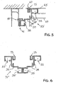
- FIGS. 5 and 6 Variants 53 ', 71' are shown to the rear post sections 53,71.
- an insertion groove 61 for the back partition 63 has been dispensed with. It is for a screw groove 73, or 73 'is provided, in which the back-partition wall 63' is screwed with a screw 67.
- the profiles can also be varied in this sense. So is in FIG. 7 a front corner profile 11 'is shown, which has no hollow profile part 26 in a modification of the profile 11. This is in addition to the insert-fixing strip 15, a helical groove formed. Inserts can therefore be fastened alternatively in the insert fixing strip 15 or the screw groove 75.
- the screw groove 75 can also serve, for example, for fastening labeling panels.
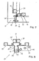
- FIG. 8 a front center post 13 'is shown, whose profile has only one opening 47 for a post holder 49 and therefore is not completely symmetrical.
- this front mullion profile 13 'and the front wall 77 of the hollow profile member 26 is set back relative to the base stops 25,25' forming walls.
- the profile 13 'the profile 13 is the same.
- a clamping U-profile 79 is provided to cover the hollow profile part 26, . This is supplied along with the doors 31 and other trim elements 45 at a relatively late time with a selectable surface. .
- the arrangement of a front stop 25,25 ', 39 for the front side of a crosspiece 37, 57 at a distance from the axis of a C-groove 15,35,55 on a post section 11,51,53,71 is a rigid angle mounting an angularly cut transverse web 37.57 on the C-groove with only a single screw 19 possible. Thanks to the arrangement of two mutually perpendicular C-grooves 15,35,55 with such end stops 25,39 A profile can be created with this profile as a post media channels in the simplest way. For this purpose, posts from such a profile 11,51,53,71 by means of transverse webs 37,57, preferably from mounting rails for attachment of cables, pipes and tubes, connected to each other.
- FIG. 9 a cross bar 81 is shown, as it is usually arranged to build the installation framework at the ends of the inventive posts.
- Figure 9.1 is a view in FIG. 9.2 a supervision and in Figure 9.3 a cross section through the profile of the crosspiece shown.
- the profile of the cross bar 81 is C-shaped formed from a sheet metal, cut to a right angle and has on the three closed sides of the C holes 83 in which installations can be attached.
- FIG. 10 a width bridge 91 is shown for the base or frontal area of the front.
- FIG. 10.1 is a view in Figure 10.2 a supervision and in FIG. 10.3 a cross section through the profile of the width web 91 shown.
- the illustrated width bridge 91 for the front is largely formed as the other transverse webs 81, but has according to the greater depth of the stop 25 on the post 51 a greater depth 89 than the crosspiece 81 for the depth webs and the width webs for the back of the installation framework on (Comparisons FIG. 9 ). This greater depth is not essential.
- the deeper Boothnstegprofil is also C-shaped from a sheet metal and has in the closed sides of the C each holes for attachment to the post and in the middle a hole for the attachment of a cover.
- FIG. 11 Such a shaft is shown over three floors.
- recesses 95 are provided through which the installation lines extend from one floor to the other.
- distributors 97 can be arranged.
- the installation shafts can be different installations be installed side by side, eg telephone, computer and power. But also plumbing, heating pipes, ventilation pipes, etc. can be accommodated in such installation shafts.
- the shaft shown is shown in front of a building wall as a plaster shaft from an installation framework with inventive posts.
- the different media in different areas in the shaft out, for example, on the left side panel EDP, rear power, and right phone.
- the installation framework can also be mounted in a three-sided masonry shaft, which is a flush installation according FIG. 12 results.
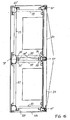
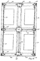
- FIG. 12 is a doubt-proof flush-mounted installation cabinet. From two posts with the profile 11 and a post with the profile 51 and four width bars 91 a front is formed. The remaining parts of the installation framework are used for installation and can be omitted, for example, in a simple wall cabinet.
- FIG. 12 is shown over several floors through installation shaft. Accordingly, recesses 95 are provided in the floor and ceiling 93. In the shaft is mounted between the floor and ceiling installation framework with two panels attached.
- This installation framework consists of three prefabricated elements; An installation ladder to be arranged on the left side from a front corner post 11 and a rear corner post 53, one lower and one upper depth web 81 and a number of transverse webs 37 of a combination rail profile for fastening both pipe clamps and cable ties; a central installation ladder comprising a front 51 a rear center post 71, connected to two upper and two lower depth webs 81, and a plurality of transverse webs 37 of a combination rail, on one side or on both sides of the installation ladder, as needed; and a third installation conductor, which corresponds to the first and is to be arranged on the right.
- These installation ladders are connected to front and rear width webs 81 below and above and to a number of combination rails 57 on the rear wall of the manhole.
- the installation of the installation framework takes place before the introduction of the underlay floor 99.
- the lower width webs 91 are therefore covered by the underlay floor 99.
- the plaster on the walls is removed (see also FIG. 13 ). This ensures a match between Wandfrow and cabinet front.
- To The cabinet front is placed on the installation framework for the installation of the cables on the installation framework and the completion of the underlay floor and wall plaster.
- the posts are clad with cladding panels in a desired color.
- a plinth panel and a lintel are used and in each field a door is hung
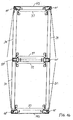
- FIG. 13 is a cross section through such a shaft shown.
- the profiles used are slightly different from the profiles in FIGS. 1 to 4 , thus, the insertion grooves 41 "and 61" are minimized, a screw-in groove 101 is formed on the front profiles 11 "and only one opening 47 is provided for inserting a flat iron angle Ribs are partially removed when the flat iron is inserted, so that a snug fit is achieved even with slight thickness variations in the flat iron used.
- FIG. 13 shown installation shaft is provided both laterally and on the rear wall with transverse webs 37, 57.
- VL flow
- VL flow
- FIG. 14 is an electric riser zone shown.
- the low power installation 105 is arranged on the left side, the power installation 107 on the rear, and the telephone installation 109 on the right.
- a distribution cabinet 111 is hung from the front into the installation framework.
- Sheet metal lining 113 attached to the posts 11 "and 53".
- FIG. 15 is a freestanding, zweeldriger installation cabinet with two doors 115 shown. This is not only the side of a sheet metal paneling attached, but also the back of the rear posts 53 "and 71".
- FIG. 16 In this front door and rear door 115 can be attached.
- the installations are only to be attached to the side installation ladders. But it can be unilaterally or bilaterally distribution boxes or fuse boards etc. attached.
- FIG. 17 Finally, a two-sided and on each side doubtful, freestanding installation cabinet is shown. It is essentially made up of two installation frames, like one in FIG. 15 is shown, composed. The two scaffolds are joined back to back. A field or compartment of the cabinet is shielded with partitions 43 opposite the other compartments. This allows the shielding of computer equipment, for example, against the influences of neighboring power lines, etc.
Landscapes
- Engineering & Computer Science (AREA)
- Power Engineering (AREA)
- Architecture (AREA)
- Civil Engineering (AREA)
- Structural Engineering (AREA)
- Assembled Shelves (AREA)
- Furniture Connections (AREA)
- Mutual Connection Of Rods And Tubes (AREA)
- Transplanting Machines (AREA)
- Medicines Containing Plant Substances (AREA)
Claims (15)
- Profilé de montant (11, 51, 53, 71) pour des montants qui doivent être reliés avec des étais transversaux (37, 57, 81, 91), avec au moins une première latte de fixation (par exemple 15, 55) et une seconde latte de fixation (par exemple 35) qui y sont formées, parallèlement à l'axe longitudinal du profilé, lesquelles lattes de fixation (15, 35, 55) se trouvent l'une par rapport à l'autre dans un angle qui divise 360° en nombres entiers, en particulier un angle de 90 degrés, et qui permettent une fixation réglable parallèlement à l'axe longitudinal du profilé d'un étai transversal (37, 57, 81, 91) sur un côté de fixation de la latte de fixation, une perpendiculaire au côté de fixation étant orientée respectivement transversalement par rapport au sens longitudinal d'un étai transversal (37, 57, 81, 91) qui doit y être fixé, caractérisé en ce que les lattes de fixation (15, 35, 55) permettent une fixation réglable en continu parallèlement à l'axe longitudinal du profilé et que respectivement une butée frontale (25, 39) est configurée sur le profilé de montant parallèlement aux lattes de fixation (15, 35, 55) pour faire buter un côté frontal (87) d'un étai transversal (37, 57, 81, 91) de telle manière que respectivement un étai transversal (37, 57, 81, 91) est fixé sur chacune des deux lattes de fixation (15, 35, 55) à la même hauteur et peut buter avec son côté frontal (87) contre la butée frontale respective (25, 39).
- Profilé de montant selon la revendication 1, caractérisé par au moins une gorge d'emboîtement (41, 61) pour emboîter une paroi de séparation (43, 63) dans le profilé de montant, laquelle gorge d'emboîtement (41, 61) est orientée de telle manière qu'une paroi de séparation (43, 63) qui y est emboîtée se trouve parallèlement à un étai transversal (37, 57, 81, 91) qui est fixé à une latte de fixation (35, 55).
- Profilé de montant selon la revendication 2, caractérisé en ce que la gorge d'emboîtement (41, 61) est placée sur le côté de la latte de fixation (35, 55) qui est opposé au côté de fixation au voisinage direct de celle-ci.
- Profilé de montant selon l'une des revendications 1 à 3, caractérisé par une section de profilé avec au moins une ouverture (47) dimensionnée pour emboîter un plat (49) dans le sens longitudinal du profilé dans une extrémité du profilé.
- Profilé de montant selon la revendication 4, caractérisé en ce qu'au moins une nervure, qui est déformable par l'emboîtement du plat, est configurée dans cette ouverture.
- Profilé de montant selon l'une des revendications 1 à 5, caractérisé en ce que la latte de fixation (15, 35, 55) est formée par une gorge en forme de C.
- Profilé de montant selon l'une des revendications 1 à 6, caractérisé en ce qu'une paroi coudée (49) est configurée entre deux lattes de fixation (35, 55), paroi coudée qui forme avec son côté convexe des butées frontales (39) pour des étais transversaux (37, 57, 81, 91) fixés à ces lattes de fixation (35, 55).
- Profilé de montant selon l'une des revendications 1 à 6, caractérisé en ce qu'une partie de profilé (26) qui fait saillie sur le devant par un côté de fixation d'une latte de fixation côté frontal (15) forme la butée frontale (25) pour un étai transversal fixé à cette latte de fixation côté frontal (15), en particulier pour un élément de socle (23) et un élément de linteau, et que l'autre butée frontale (39) est configurée sur le profilé de montant (11, 51) sur le côté de cette latte de fixation côté frontal (15) qui est opposé au côté de fixation.
- Profilé de montant selon la revendication 8, caractérisé en ce qu'une gorge (27) est configurée pour un profilé d'étanchéité entre la latte de fixation côté frontal (15) et la butée frontale (25) formée par la partie de profilé côté frontal (26).
- Profilé de montant selon l'une des revendications 1 à 9 en relation avec la revendication 2, caractérisé en ce qu'au moins une gorge d'emboîtement (41, 61) est configurée pour une paroi de séparation de manière périphérique sur le profilé (11, 53, 71) de telle manière qu'une paroi de séparation plane qui y est emboîtée est orientée parallèlement au sens d'un étai transversal fixé au profilé.
- Profilé de montant selon l'une des revendications 1 à 10 en relation de la revendication 2, caractérisé en ce que le profilé (51, 51', 71, 71') est configuré substantiellement symétrique miroir et qu'une gorge d'emboîtement est configurée sur le plan de symétrie.
- Set de profilés de montant avec au moins deux profilés différents (11, 51) avec au moins une première latte de fixation (par exemple 15, 55) et une seconde latte de fixation (par exemple 35) qui y sont formées, parallèlement à l'axe longitudinal du profilé, lesquelles lattes de fixation (15, 35, 55) se trouvent l'une par rapport à l'autre dans un angle qui divise 360° en nombres entiers, en particulier un angle de 90 degrés, et qui permettent une fixation réglable parallèlement à l'axe longitudinal du profilé d'un étai transversal (37, 57, 81, 91) sur un côté de fixation de la latte de fixation, une perpendiculaire au côté de fixation étant orientée respectivement transversalement par rapport au sens longitudinal d'un étai transversal (37, 57, 81, 91) qui doit y être fixé et transversalement par rapport à l'axe longitudinal du profilé, caractérisé en ce que les lattes de fixation (15, 35, 55) permettent une fixation par serrage réglable en continu parallèlement à l'axe longitudinal du profilé et que respectivement une butée frontale (25, 39) est configurée sur le profilé de montant parallèlement aux lattes de fixation (15, 35, 55) pour faire buter un côté frontal (87) d'un étai transversal (37, 57, 81, 91) de telle manière que respectivement un étai transversal (37, 57, 81, 91) est fixé sur chacune des deux lattes de fixation (15, 35, 55) à la même hauteur et peut buter avec son côté frontal (87) contre la butée frontale respective (25, 39), une partie de profilé côté frontal (26) formant la butée frontale (25) pour un étai transversal (91) qui doit être fixé sur une latte de fixation côté frontal (15) et l'autre butée frontale (39) étant configurée sur le côté de cette latte de fixation côté frontal (15) qui est opposé au côté de fixation et que, pour un premier profilé (11), une latte de fixation (15) est configurée uniquement d'un côté sur la partie de profilé (26) qui forme la butée frontale côté frontal (25) et que, pour le second profilé (51), deux lattes de fixation (15, 15') sont configurées symétriquement des deux côtés sur la partie de profilé (26) qui forme la butée frontale côté frontal.
- Set de profilés de montant selon la revendication 12, caractérisé par un troisième profilé de montant (53) avec deux lattes de fixation (35, 55) qui présente, entre les deux lattes de fixation (35, 55), une paroi coudée (59) qui forme avec son côté convexe des butées frontales (39) pour des étais transversaux (37, 57, 81, 91) fixés à ces lattes de fixation (35, 55) et par un quatrième profilé de montant (71) correspondant à un troisième profilé de montant (53) doublé substantiellement en symétrie miroir avec une troisième latte de fixation supplémentaire (35') et une quatrième latte de fixation supplémentaire (55') sur une seconde paroi coudée (59'), lesquelles lattes de fixation supplémentaires (35', 55') et laquelle seconde paroi coudée (59') sont placées symétriques miroir par rapport aux deux premières lattes de fixation (35, 55) et à la première paroi coudée (59).
- Set de construction constitué par un jeu de profilés de montant selon l'une des revendications 12 ou 13, de profilés pour fabriquer des étais transversaux (37, 57, 81, 91) et des moyens de fixation (19, 21) pour fixer les étais transversaux (37, 57, 81, 91) sur les profilés de montant (11, 51, 53, 71).
- Set de construction selon la revendication 14, caractérisé par des montants (11, 51, 53, 71) et des étais transversaux (37, 57, 81,91) raccourcis et éventuellement par des parois de séparation (43, 63) découpées sur mesure ainsi qu'au moins un élément de fermeture (31) pour fermer autant que possible une ouverture formée entre deux montants.
Applications Claiming Priority (2)
| Application Number | Priority Date | Filing Date | Title |
|---|---|---|---|
| CH23482000 | 2000-12-04 | ||
| CH02348/00A CH695753A5 (de) | 2000-12-04 | 2000-12-04 | Pfostenprofil. |
Publications (2)
| Publication Number | Publication Date |
|---|---|
| EP1211770A1 EP1211770A1 (fr) | 2002-06-05 |
| EP1211770B1 true EP1211770B1 (fr) | 2008-09-10 |
Family
ID=4568706
Family Applications (1)
| Application Number | Title | Priority Date | Filing Date |
|---|---|---|---|
| EP01811171A Expired - Lifetime EP1211770B1 (fr) | 2000-12-04 | 2001-12-03 | Traverse profilée |
Country Status (4)
| Country | Link |
|---|---|
| EP (1) | EP1211770B1 (fr) |
| AT (1) | ATE408255T1 (fr) |
| CH (1) | CH695753A5 (fr) |
| DE (1) | DE50114301D1 (fr) |
Families Citing this family (1)
| Publication number | Priority date | Publication date | Assignee | Title |
|---|---|---|---|---|
| CN110313718B (zh) * | 2019-07-01 | 2024-07-26 | 贵州锦程铝业科技有限公司 | 一种应用于柜体的铝合金型材 |
Family Cites Families (2)
| Publication number | Priority date | Publication date | Assignee | Title |
|---|---|---|---|---|
| DE9207806U1 (de) * | 1992-06-10 | 1992-08-27 | Knürr-Mechanik für die Elektronik AG, 8000 München | Hohlprofil |
| DE4445403B4 (de) * | 1993-12-27 | 2006-04-06 | Mirai Industry Co, Ltd. | Kabelgestell und Kabelgestellhalter |
-
2000
- 2000-12-04 CH CH02348/00A patent/CH695753A5/de not_active IP Right Cessation
-
2001
- 2001-12-03 AT AT01811171T patent/ATE408255T1/de active
- 2001-12-03 EP EP01811171A patent/EP1211770B1/fr not_active Expired - Lifetime
- 2001-12-03 DE DE50114301T patent/DE50114301D1/de not_active Expired - Lifetime
Also Published As
| Publication number | Publication date |
|---|---|
| DE50114301D1 (de) | 2008-10-23 |
| ATE408255T1 (de) | 2008-09-15 |
| CH695753A5 (de) | 2006-08-15 |
| EP1211770A1 (fr) | 2002-06-05 |
Similar Documents
| Publication | Publication Date | Title |
|---|---|---|
| DE69316247T2 (de) | Arbeitsraumtrennwandsystem | |
| DE10136681C2 (de) | Rahmengestell | |
| DE3726255C2 (de) | Trennwand | |
| DE2908153C2 (fr) | ||
| DE69701988T2 (de) | Versetzbares trennwandsystem | |
| EP1870529B1 (fr) | Mur/ensemble de coffre pour une construction de cadre | |
| DE19960535A1 (de) | Trennwandaufbau | |
| EP1211770B1 (fr) | Traverse profilée | |
| DE9203467U1 (de) | Bauelementsatz und daraus hergestellte Zellenanordnung | |
| DE19712345A1 (de) | Wandsystem, insbesondere für Präsentationsstände | |
| DE69724026T2 (de) | Ausbaubare Schaltschrank mit integriertem Sockel | |
| DE8709026U1 (de) | Fachwerk für Decken und Wände | |
| DE1591623B1 (de) | Schrank fuer Geraete der Nachrichtentechnik | |
| DE102017120254A1 (de) | Winkelelement und Laibungsverkleidung mit einem Winkelelement | |
| AT405200B (de) | Vorgesetzte wandverkleidungen, verfahren zu deren herstellung und montageprofil hiefür | |
| DE102015108401A1 (de) | Mobile modulare Trennwand | |
| DE4236763A1 (en) | Soundproof cubicle with self-supporting frame - has Z=section uprights and cross-members with flanges at right angles to web and has panels filling in spaces supported by sealing components | |
| WO2011131641A1 (fr) | Ensemble armoire encastré | |
| DE29904707U1 (de) | Rahmengestell für einen Schrank | |
| DE10328405B4 (de) | Schaltschrank | |
| DE10235918B4 (de) | Montagesystem für Möbel und Verfahren zur Montage von Möbeln | |
| DE3600933A1 (de) | Zerlegbare stellwand, insbesondere fuer ausstellungen | |
| EP0213451B1 (fr) | Rail pour une construction de support d'un bardage de mur ou plafond | |
| DE3426831A1 (de) | Aus vorgefertigten wand- und deckentafeln bestehendes raumbausystem fuer schiffe und aehnliche baukoerper | |
| EP4130405A1 (fr) | Système de construction préfabriquée |
Legal Events
| Date | Code | Title | Description |
|---|---|---|---|
| PUAI | Public reference made under article 153(3) epc to a published international application that has entered the european phase |
Free format text: ORIGINAL CODE: 0009012 |
|
| AK | Designated contracting states |
Kind code of ref document: A1 Designated state(s): AT BE CH CY DE DK ES FI FR GB GR IE IT LI LU MC NL PT SE TR |
|
| AX | Request for extension of the european patent |
Free format text: AL;LT;LV;MK;RO;SI |
|
| 17P | Request for examination filed |
Effective date: 20021004 |
|
| AKX | Designation fees paid |
Designated state(s): AT BE CH CY DE DK ES FI FR GB GR IE IT LI LU MC NL PT SE TR |
|
| RAP1 | Party data changed (applicant data changed or rights of an application transferred) |
Owner name: GANTENBEIN, ULRICH |
|
| RIN1 | Information on inventor provided before grant (corrected) |
Inventor name: GANTENBEIN, ULRICH |
|
| GRAP | Despatch of communication of intention to grant a patent |
Free format text: ORIGINAL CODE: EPIDOSNIGR1 |
|
| GRAS | Grant fee paid |
Free format text: ORIGINAL CODE: EPIDOSNIGR3 |
|
| GRAA | (expected) grant |
Free format text: ORIGINAL CODE: 0009210 |
|
| AK | Designated contracting states |
Kind code of ref document: B1 Designated state(s): AT BE CH CY DE DK ES FI FR GB GR IE IT LI LU MC NL PT SE TR |
|
| REG | Reference to a national code |
Ref country code: GB Ref legal event code: FG4D Free format text: NOT ENGLISH |
|
| REG | Reference to a national code |
Ref country code: CH Ref legal event code: EP |
|
| REG | Reference to a national code |
Ref country code: IE Ref legal event code: FG4D Free format text: LANGUAGE OF EP DOCUMENT: GERMAN |
|
| REF | Corresponds to: |
Ref document number: 50114301 Country of ref document: DE Date of ref document: 20081023 Kind code of ref document: P |
|
| REG | Reference to a national code |
Ref country code: CH Ref legal event code: NV Representative=s name: RIEDERER HASLER & PARTNER PATENTANWAELTE AG |
|
| PG25 | Lapsed in a contracting state [announced via postgrant information from national office to epo] |
Ref country code: FI Free format text: LAPSE BECAUSE OF FAILURE TO SUBMIT A TRANSLATION OF THE DESCRIPTION OR TO PAY THE FEE WITHIN THE PRESCRIBED TIME-LIMIT Effective date: 20080910 |
|
| NLV1 | Nl: lapsed or annulled due to failure to fulfill the requirements of art. 29p and 29m of the patents act | ||
| REG | Reference to a national code |
Ref country code: IE Ref legal event code: FD4D |
|
| PG25 | Lapsed in a contracting state [announced via postgrant information from national office to epo] |
Ref country code: IE Free format text: LAPSE BECAUSE OF FAILURE TO SUBMIT A TRANSLATION OF THE DESCRIPTION OR TO PAY THE FEE WITHIN THE PRESCRIBED TIME-LIMIT Effective date: 20080910 Ref country code: ES Free format text: LAPSE BECAUSE OF FAILURE TO SUBMIT A TRANSLATION OF THE DESCRIPTION OR TO PAY THE FEE WITHIN THE PRESCRIBED TIME-LIMIT Effective date: 20081221 |
|
| PG25 | Lapsed in a contracting state [announced via postgrant information from national office to epo] |
Ref country code: NL Free format text: LAPSE BECAUSE OF FAILURE TO SUBMIT A TRANSLATION OF THE DESCRIPTION OR TO PAY THE FEE WITHIN THE PRESCRIBED TIME-LIMIT Effective date: 20080910 Ref country code: PT Free format text: LAPSE BECAUSE OF FAILURE TO SUBMIT A TRANSLATION OF THE DESCRIPTION OR TO PAY THE FEE WITHIN THE PRESCRIBED TIME-LIMIT Effective date: 20090210 |
|
| BERE | Be: lapsed |
Owner name: GANTENBEIN, ULRICH Effective date: 20081231 |
|
| PLBE | No opposition filed within time limit |
Free format text: ORIGINAL CODE: 0009261 |
|
| STAA | Information on the status of an ep patent application or granted ep patent |
Free format text: STATUS: NO OPPOSITION FILED WITHIN TIME LIMIT |
|
| PG25 | Lapsed in a contracting state [announced via postgrant information from national office to epo] |
Ref country code: MC Free format text: LAPSE BECAUSE OF NON-PAYMENT OF DUE FEES Effective date: 20081231 Ref country code: DK Free format text: LAPSE BECAUSE OF FAILURE TO SUBMIT A TRANSLATION OF THE DESCRIPTION OR TO PAY THE FEE WITHIN THE PRESCRIBED TIME-LIMIT Effective date: 20080910 |
|
| 26N | No opposition filed |
Effective date: 20090611 |
|
| PG25 | Lapsed in a contracting state [announced via postgrant information from national office to epo] |
Ref country code: BE Free format text: LAPSE BECAUSE OF NON-PAYMENT OF DUE FEES Effective date: 20081231 |
|
| PG25 | Lapsed in a contracting state [announced via postgrant information from national office to epo] |
Ref country code: SE Free format text: LAPSE BECAUSE OF FAILURE TO SUBMIT A TRANSLATION OF THE DESCRIPTION OR TO PAY THE FEE WITHIN THE PRESCRIBED TIME-LIMIT Effective date: 20081210 |
|
| PG25 | Lapsed in a contracting state [announced via postgrant information from national office to epo] |
Ref country code: LU Free format text: LAPSE BECAUSE OF NON-PAYMENT OF DUE FEES Effective date: 20081203 Ref country code: CY Free format text: LAPSE BECAUSE OF FAILURE TO SUBMIT A TRANSLATION OF THE DESCRIPTION OR TO PAY THE FEE WITHIN THE PRESCRIBED TIME-LIMIT Effective date: 20080910 |
|
| PG25 | Lapsed in a contracting state [announced via postgrant information from national office to epo] |
Ref country code: TR Free format text: LAPSE BECAUSE OF FAILURE TO SUBMIT A TRANSLATION OF THE DESCRIPTION OR TO PAY THE FEE WITHIN THE PRESCRIBED TIME-LIMIT Effective date: 20080910 |
|
| PG25 | Lapsed in a contracting state [announced via postgrant information from national office to epo] |
Ref country code: GR Free format text: LAPSE BECAUSE OF FAILURE TO SUBMIT A TRANSLATION OF THE DESCRIPTION OR TO PAY THE FEE WITHIN THE PRESCRIBED TIME-LIMIT Effective date: 20081211 |
|
| REG | Reference to a national code |
Ref country code: FR Ref legal event code: PLFP Year of fee payment: 15 |
|
| REG | Reference to a national code |
Ref country code: FR Ref legal event code: PLFP Year of fee payment: 16 |
|
| PGFP | Annual fee paid to national office [announced via postgrant information from national office to epo] |
Ref country code: DE Payment date: 20161213 Year of fee payment: 16 Ref country code: GB Payment date: 20161222 Year of fee payment: 16 |
|
| PGFP | Annual fee paid to national office [announced via postgrant information from national office to epo] |
Ref country code: FR Payment date: 20161222 Year of fee payment: 16 Ref country code: AT Payment date: 20161222 Year of fee payment: 16 |
|
| PGFP | Annual fee paid to national office [announced via postgrant information from national office to epo] |
Ref country code: IT Payment date: 20161223 Year of fee payment: 16 |
|
| REG | Reference to a national code |
Ref country code: DE Ref legal event code: R119 Ref document number: 50114301 Country of ref document: DE |
|
| REG | Reference to a national code |
Ref country code: AT Ref legal event code: MM01 Ref document number: 408255 Country of ref document: AT Kind code of ref document: T Effective date: 20171203 |
|
| GBPC | Gb: european patent ceased through non-payment of renewal fee |
Effective date: 20171203 |
|
| REG | Reference to a national code |
Ref country code: FR Ref legal event code: ST Effective date: 20180831 |
|
| PG25 | Lapsed in a contracting state [announced via postgrant information from national office to epo] |
Ref country code: IT Free format text: LAPSE BECAUSE OF NON-PAYMENT OF DUE FEES Effective date: 20171203 Ref country code: FR Free format text: LAPSE BECAUSE OF NON-PAYMENT OF DUE FEES Effective date: 20180102 Ref country code: DE Free format text: LAPSE BECAUSE OF NON-PAYMENT OF DUE FEES Effective date: 20180703 |
|
| PG25 | Lapsed in a contracting state [announced via postgrant information from national office to epo] |
Ref country code: AT Free format text: LAPSE BECAUSE OF NON-PAYMENT OF DUE FEES Effective date: 20171203 Ref country code: GB Free format text: LAPSE BECAUSE OF NON-PAYMENT OF DUE FEES Effective date: 20171203 |
|
| PGFP | Annual fee paid to national office [announced via postgrant information from national office to epo] |
Ref country code: CH Payment date: 20201222 Year of fee payment: 20 |
|
| REG | Reference to a national code |
Ref country code: CH Ref legal event code: PL |