EP1870529B1 - Mur/ensemble de coffre pour une construction de cadre - Google Patents
Mur/ensemble de coffre pour une construction de cadre Download PDFInfo
- Publication number
- EP1870529B1 EP1870529B1 EP07105718A EP07105718A EP1870529B1 EP 1870529 B1 EP1870529 B1 EP 1870529B1 EP 07105718 A EP07105718 A EP 07105718A EP 07105718 A EP07105718 A EP 07105718A EP 1870529 B1 EP1870529 B1 EP 1870529B1
- Authority
- EP
- European Patent Office
- Prior art keywords
- wall
- cupboard
- profile
- upright
- forming
- Prior art date
- Legal status (The legal status is an assumption and is not a legal conclusion. Google has not performed a legal analysis and makes no representation as to the accuracy of the status listed.)
- Active
Links
- 238000010276 construction Methods 0.000 title abstract description 18
- 239000000463 material Substances 0.000 claims description 9
- 239000002023 wood Substances 0.000 claims description 8
- 239000010440 gypsum Substances 0.000 claims description 4
- 229910052602 gypsum Inorganic materials 0.000 claims description 4
- 238000009432 framing Methods 0.000 claims 2
- 238000009434 installation Methods 0.000 description 4
- 230000015572 biosynthetic process Effects 0.000 description 3
- 239000003063 flame retardant Substances 0.000 description 3
- 239000002184 metal Substances 0.000 description 3
- 239000011094 fiberboard Substances 0.000 description 2
- 238000005192 partition Methods 0.000 description 2
- 238000005253 cladding Methods 0.000 description 1
- 238000003780 insertion Methods 0.000 description 1
- 230000037431 insertion Effects 0.000 description 1
Images


Classifications
-
- E—FIXED CONSTRUCTIONS
- E04—BUILDING
- E04B—GENERAL BUILDING CONSTRUCTIONS; WALLS, e.g. PARTITIONS; ROOFS; FLOORS; CEILINGS; INSULATION OR OTHER PROTECTION OF BUILDINGS
- E04B2/00—Walls, e.g. partitions, for buildings; Wall construction with regard to insulation; Connections specially adapted to walls
- E04B2/74—Removable non-load-bearing partitions; Partitions with a free upper edge
- E04B2/7407—Removable non-load-bearing partitions; Partitions with a free upper edge assembled using frames with infill panels or coverings only; made-up of panels and a support structure incorporating posts
- E04B2/7453—Removable non-load-bearing partitions; Partitions with a free upper edge assembled using frames with infill panels or coverings only; made-up of panels and a support structure incorporating posts with panels and support posts, extending from floor to ceiling
- E04B2/7457—Removable non-load-bearing partitions; Partitions with a free upper edge assembled using frames with infill panels or coverings only; made-up of panels and a support structure incorporating posts with panels and support posts, extending from floor to ceiling with wallboards attached to the outer faces of the posts, parallel to the partition
-
- A—HUMAN NECESSITIES
- A47—FURNITURE; DOMESTIC ARTICLES OR APPLIANCES; COFFEE MILLS; SPICE MILLS; SUCTION CLEANERS IN GENERAL
- A47B—TABLES; DESKS; OFFICE FURNITURE; CABINETS; DRAWERS; GENERAL DETAILS OF FURNITURE
- A47B47/00—Cabinets, racks or shelf units, characterised by features related to dismountability or building-up from elements
-
- E—FIXED CONSTRUCTIONS
- E04—BUILDING
- E04B—GENERAL BUILDING CONSTRUCTIONS; WALLS, e.g. PARTITIONS; ROOFS; FLOORS; CEILINGS; INSULATION OR OTHER PROTECTION OF BUILDINGS
- E04B2/00—Walls, e.g. partitions, for buildings; Wall construction with regard to insulation; Connections specially adapted to walls
- E04B2/74—Removable non-load-bearing partitions; Partitions with a free upper edge
- E04B2002/7483—Details of furniture, e.g. tables or shelves, associated with the partitions
Definitions
- the invention relates to a wall / cabinet assembly with a frame construction with horizontal frame profiles, in particular standardized UW profiles, and vertical upright profiles and associated side wall elements.
- Drywall walls are generally known from the prior art, which consist of a frame construction and drywall panels fastened thereto, in particular plasterboard panels screwed thereto.
- the frame construction consists essentially of vertical upright profiles, in particular standardized CW profiles, which are inserted and connected to horizontal frame profiles, in particular standardized UW profiles, above and below.
- Each stand profile has a c-shaped cross-section and each frame profile has a u-shaped.
- Such drywall are used as walls, stems and panels.
- the present invention based on the object to provide a wall / cabinet assembly with a frame construction, in particular a drywall, a pretext and / or a panel, which is characterized by a simple and quick installation.
- a new wall construction / furniture element that combines the functions of the upright profile within a drywall and a side wall of a cabinet in itself. It thus eliminates the assembly steps of the separate installation of the stator profile and then attaching the side wall element in the drywall. This happens now simply by the pivoting of the side wall element with its stand profile between the frame profiles on the wall and ceiling.
- the side wall element has a stator part and a cabinet part, adjoins the stator part, the stator profile, and the stator profile is spaced with its stator part via an incision of the cabinet part.
- commercial frame profiles can be used, which do not have to be adapted to the side wall elements.
- the side wall element has a side wall part and a cabinet part, and the upright profile projects beyond the cupboard part at both ends. Even so, commercially available frame profiles can be used. In this case, then projects the stand profile at both ends on the cabinet part by means of a guide member and on the cabinet part a foot is attached.
- the upright profile has a greater wall thickness than the side wall element.
- a further increase in stability and better attachment of drywall panels results from the fact that the stand profile in Extending laterally outwardly in both directions with respect to the sidewall member.
- the upright profile extends laterally outwards in one direction with respect to the side wall element.
- a cabinet projecting from the wall into a room in one direction is achieved by arranging the stand profile on a longitudinal edge of the side wall element.
- a cabinet that projects in both directions from the created wall / cabinet assembly is achieved in that the stand profile is arranged with the stator part in the central region of the side wall member.
- Preferred materials for the upright profile and the side wall element are wood-based materials or fire-retardant gypsum fiber boards.
- the wall / cabinet assembly defines two spaced and held by UW frame profiles side wall panels a cabinet interior and thus form a cabinet with a wall construction.
- This cabinet gets its back wall through the closed by a drywall panel wall surface.
- the wall / cabinet assembly thus forms the vertical construction of a stud wall and / or wall and thus a cabinet in a wall.
- the cabinet has a rear wall, which is formed by a drywall of a drywall, and the side wall elements emerge from the drywall.
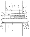
- FIG. 1 a perspective view of a frame construction 1 of a wall / cabinet assembly 2 is shown.
- the frame structure 1 consists essentially of an upper horizontal U-shaped frame profile 3o, in particular a standardized UW profile which is fixed to a ceiling 4, and an oppositely arranged lower frame profile 3u, which is also designed in particular as a standardized UW profile and is fixed on a floor 5.
- Each of the frame profiles 3o, 3u has two legs 3b, which are aligned parallel to one another and vertically aligned in the installed state and are held together at one end via a base part 3c to the U-profile.
- the legs 3b are at a distance a (see FIG. 2 ) spaced apart from each other and thus define laterally an opening 3a.
- the openings 3a of the upper and lower frame profiles 3o, 3u are facing each other in the installed state and bounded laterally by legs 3b.
- 3u stator profiles 6 are inserted into the openings 3a of the upper and lower frame profiles and connected thereto.
- the stand profile 6 is part of a side wall element 7 of the wall / cabinet assembly. 2
- FIG. 1 In the FIG. 1 are a total of three side wall elements 7 shown with the help of which now a wall / cabinet assembly 2 with two cabinets 10 can be constructed.
- the side wall elements 7 bound each laterally two cabinet interior spaces 10i.
- the rear wall of the cabinets 10 is formed by a fixed to the frame profiles 3 a, 3 u and the stator profiles 6 drywall 14, in particular plasterboard. Also, the cabinets 10 can be closed at the front via doors 15. It is also possible to run these as open shelves. In both cases, 7 floors not shown can be fastened between the side wall elements. In order to secure these shelves and the doors to the side wall elements 7 there rows of holes 8 are provided which serve to receive floor supports or for fastening hinges. The formation and alignment of such rows of holes 8 is well known in the art.
- FIG. 1 It can be seen that with the wall / cabinet assembly 2 with its frame structure 1 complete partitions can be realized or the wall / cabinet assembly 2 can also be combined with normal drywall. Then joins, for example, to the left side wall element 7, a drywall with conventional stand profiles made of sheet metal, in particular standardized CW profiles on. Also, the wall / cabinet assembly 2 may begin directly against a wall and extend therefrom at an angle, preferably at right angles.
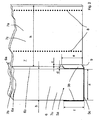
- FIG. 2 is a perspective enlargement of FIG. 1 from the region of the lower end 7u of a side wall element 7 in combination with the lower frame profile 3u shown. From this figure, details of the structure of the side wall member 7 and its connection to the lower frame profile 3u can be seen.
- the side wall member 7 consists of a rectangular and flat side wall plate 7 a, which is provided with the rows of holes 8 and merges into the upright profile 6.
- the side wall plate 7a thus has a cabinet part 7c and a stator part 7b.
- the cabinet part 7c of the side wall panel 7a limits the cabinet interior 10i laterally and thus its width corresponds to a kind of useful depth h, of which still the space for the drywall 14, which forms the rear wall of the cabinet 11 would deduct.
- a strip 6a is laterally applied to the side wall plate 7a, so that the actual upright profile is given a square-shaped cross-section which is sandwiched by the first strip 6a, the upright part 7b of the side wall plate 7a and the further strip 6a.
- the width b of the bars is chosen so that these in approximately corresponds to the distance a between the legs 3b of the lower frame profile 3o.
- the stator profiles 6 can be inserted into the frame profiles 3o, 3u, it is necessary that in the side wall plate 7a a recess 9 is provided, the width c at least wider than the thickness d of the legs 3b of the frame profiles 3o, 3u.
- the width c is twice the thickness d.
- the incision 9 it is necessary for the incision 9 to have a length e which is at least slightly greater than the height f of the legs 3b of the frame profiles 3o, 3u.
- the incision 9 connects directly to the upright profile 6 with its wall surface 6b and thus the incision 9 separates the upright profile 6 from the cupboard part 7c of the side wall plate 7a.
- the legs 3b of the frame profiles 3o, 3u facing wall surface 6b of the stator profile 6 is thus aligned with the cut surface of the incision 9 and the stator part 7b forms another part of the wall surface 6b of the stator profile 6.
- the stator profile 6 in the opening 3a of the frame profile 3o , 3u are plugged without the side wall plate 7a of the side wall member 7 is placed on the upper edge of one of the two legs 3b of the lower frame profile 3u.
- FIG. 3 a perspective view of a lower end 7u of a side wall member 7, wherein the stand profile 6 and the side wall plate 7a are configured in a second embodiment.
- the upright profile 6 is formed as a cuboid square timber with a groove 6c, in which the inner end 7c of the side wall plate 7a is inserted and connected there.
- the insertion depth g is equal to the depth of the groove c and matched with the position of the recess 9 in the side wall plate 7a.
- the recess 9 aligned with the wall surface 6b of the stator profile 6.
- the width b of the stator profile 6 is substantially equal to the distance a of the legs 3b match.
- FIG. 4 is a perspective view of the side wall element 7 after FIG. 2 shown in a third embodiment.
- This side wall element 7 differs from the side wall element 7 accordingly FIG. 1 in that the upright profile 6 is arranged in the middle region of the side wall plate 7a.
- the to Formation of the upright profile 6 required strips 6a are thus fixed in the central region on the outer sides of the side wall panel 7a.
- a lower cabinet or an accessible from both opposite sides of the wall / cabinet assembly 2 cabinet 10 can be realized.
- a wall / cabinet assembly 2 with two back-to-back cabinets 10 to realize.
- the wall / cabinet assembly 2 may have different depths of use h.
- the upright profile 6 is made only with a single bar 6a, so that the side wall element 7 can connect flush to the wall.
- the wall components 2 i. the uprights 6 and side wall elements 7, wood materials, plasterboard and / or similar materials are used.
- the side wall elements 7 and the stator profiles 6 are made of fire-retardant gypsum fiber boards, for which there is a corresponding fire protection record.
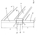
- FIG. 5 Fig. 12 is a perspective detail view of the portion of a lower end 7u of a side wall member 7 in a fourth embodiment.
- This fourth embodiment differs substantially from the previous embodiments, in that the formation of the incision 9 has been dispensed with.
- the lower and the upper frame profile 3o, 3u was formed as a wood construction part.
- This frame profile 3o, 3u also has two legs 3b and a base part 3c and an opening 3a. Due to the use of wood as a material, the legs 3b and the base part 3c have larger wall thicknesses.
- the side wall member 7 has no incision between the stator part 7b and the cabinet part 7c.
- the width b of the stator profile 6 corresponds to the width k of the frame profile 3o, 3u. So that the side wall element 7 reaches a sufficient stability, a foot 11 is arranged below the side wall plate 7a. The foot 11 is arranged in the stand profile 6 facing away from the region of the side wall plate 7a and adjustable in height to compensate for unevenness of the bottom 5 can.
- a downwardly outstanding guide element 12 is fastened in the form of a sheet metal bracket whose width I of the width a (see FIG. 5 ) corresponds to the opening 3a.
- the length of the guide element 12 corresponds approximately to the depth f of the opening 3a, but may also be shorter, since its function is in the horizontal orientation of the stator profile 6 to the lower frame section 3u.
- FIG. 6 is a perspective view of the lower end of a side wall member 7 after FIG. 5 shown.
- the guide element 12 is a sheet metal bracket which has a pointed shape and is fastened by its ends to the upright part 7b of the side wall panel 7a.
- the strips 6a are divided into two strips 6a, which form a further groove 13 whose width corresponds to the width of the opening 3a.
Landscapes
- Engineering & Computer Science (AREA)
- Architecture (AREA)
- Electromagnetism (AREA)
- Civil Engineering (AREA)
- Structural Engineering (AREA)
- Physics & Mathematics (AREA)
- Assembled Shelves (AREA)
- Residential Or Office Buildings (AREA)
- Bathtubs, Showers, And Their Attachments (AREA)
- Panels For Use In Building Construction (AREA)
- Distribution Board (AREA)
- Furniture Connections (AREA)
- Load-Bearing And Curtain Walls (AREA)
Claims (14)
- Agencement formant Cloison/Placard (2), ledit agencement possédant une structure formant cadre (1) d'une cloison, notamment une cloison en plaque de plâtre, qui comprend des profilés de cadre horizontaux (3o, 3u), notamment des profilés en U normalisées, et des profilés verticaux formant montants (6), les profilés de cadre (3o, 3u) et les profilés formant montants (6) pouvant être dotés d'une plaque (14) de façon à former une cloison, caractérisé en ce que le profilé formant montant (6) est assemblé à un élément formant paroi latérale (7) d'un placard (10) respectivement d'une étagère pour former un élément de construction, et en ce que l'élément formant paroi latérale (7) s'étend depuis la structure formant cadre (1).
- Agencement formant Cloison/Placard selon la revendication 1, caractérisé en ce que le profilé formant montant (6) est assemblé à l'élément formant paroi latérale (7) pour former un élément de construction de manière à effectuer un montage commun.
- Agencement formant Cloison/Placard selon la revendication 1 ou 2, caractérisé en ce que le profilé formant montant (6) est fabriqué à partir de matériaux dérivés du bois et de panneaux de fibres de plâtre.
- Agencement formant Cloison/Placard selon l'une des revendications 1 à 3, caractérisé en ce que l'élément formant paroi latérale (7) comporte une partie côté montant (7b) et une partie côté placard (7c), en ce que le profilé formant montant (6) se raccorde à la partie côté montant (7b), et en ce que le profilé formant montant (6) est espacé, avec sa partie côté montant (7b), de la partie côté placard (7a) par une encoche (9).
- Agencement formant Cloison/Placard selon l'une des revendications 1 à 4, caractérisé en ce que l'élément formant paroi latérale (7) comporte une partie côté paroi latérale (7b) et une partie côté placard (7c), et en ce que le profilé formant montant (6) fait dépasse la partie côté placard (7a) aux deux extrémités.
- Agencement formant Cloison/Placard selon la revendication 5, caractérisé en ce que le profilé formant montant (6) dépasse la partie côté placard (7c) aux deux extrémités au moyen d'un élément de guidage (12), et en ce qu'un pied (11) est fixé à la partie côté placard (7c).
- Agencement formant Cloison/Placard selon l'une des revendications 4 à 6, caractérisé en ce que le profilé formant montant (6) a une épaisseur de paroi (i) qui est supérieure à l'épaisseur de paroi (j) de l'élément formant paroi latérale (7).
- Agencement formant Cloison/Placard selon la revendication 7, caractérisé en ce que le profilé formant montant (6) s'étend latéralement vers l'extérieur dans les deux directions par référence à l'élément formant paroi latérale (7).
- Agencement formant Cloison/Placard selon la revendication 7, caractérisé en ce que le profilé formant montant (6) s'étend latéralement vers l'extérieur dans une seule direction par référence à l'élément formant paroi latérale (7).
- Agencement formant Cloison/Placard selon l'une des revendications 1 à 9, caractérisé en ce que le profilé formant montant (6) est disposé au niveau d'un bord longitudinal de l'élément formant paroi latérale (7).
- Agencement formant Cloison/Placard selon l'une des revendications 1 à 9, caractérisé en ce que le profilé formant montant (6) est disposé, avec la partie côté montant (7b), dans la région médiane de l'élément formant paroi latérale (7).
- Agencement formant Cloison/Placard selon l'une des revendications 1 à 11, caractérisé en ce que le profilé formant montant (6) et l'élément formant paroi latérale (7) sont fabriqués à partir de matériaux dérivé du bois et de plaques de fibres de plâtre ignifuges.
- Agencement formant Cloison/Placard selon l'une des revendications 1 à 12, caractérisé en ce que deux éléments formant parois latérales (7), espacés l'un de l'autre, délimitent un espace intérieur de placard (10i) et forment ainsi un placard (11) dans une construction murale.
- Agencement formant Cloison/Placard selon l'une des revendications 1 à 13, caractérisé en ce que le placard (11) comporte une paroi arrière qui est formée par un panneau de plaque de plâtre (14) d'une cloison en plaque de plâtre, et en ce que les éléments formant parois latérales (7) font saillie de la cloison en plaque de plâtre.
Priority Applications (1)
| Application Number | Priority Date | Filing Date | Title |
|---|---|---|---|
| PL07105718T PL1870529T3 (pl) | 2006-06-22 | 2007-04-05 | Zabudowa ściana/szafa z konstrukcją ramową |
Applications Claiming Priority (2)
| Application Number | Priority Date | Filing Date | Title |
|---|---|---|---|
| DE202006009713 | 2006-06-22 | ||
| DE202006016408 | 2006-10-26 |
Publications (2)
| Publication Number | Publication Date |
|---|---|
| EP1870529A1 EP1870529A1 (fr) | 2007-12-26 |
| EP1870529B1 true EP1870529B1 (fr) | 2009-06-03 |
Family
ID=38566775
Family Applications (1)
| Application Number | Title | Priority Date | Filing Date |
|---|---|---|---|
| EP07105718A Active EP1870529B1 (fr) | 2006-06-22 | 2007-04-05 | Mur/ensemble de coffre pour une construction de cadre |
Country Status (6)
| Country | Link |
|---|---|
| US (1) | US20080001511A1 (fr) |
| EP (1) | EP1870529B1 (fr) |
| AT (1) | ATE433020T1 (fr) |
| DE (1) | DE502007000812D1 (fr) |
| ES (1) | ES2328082T3 (fr) |
| PL (1) | PL1870529T3 (fr) |
Cited By (1)
| Publication number | Priority date | Publication date | Assignee | Title |
|---|---|---|---|---|
| WO2011131641A1 (fr) | 2010-04-20 | 2011-10-27 | Trel Systems Ag | Ensemble armoire encastré |
Families Citing this family (5)
| Publication number | Priority date | Publication date | Assignee | Title |
|---|---|---|---|---|
| US8813980B1 (en) | 2009-12-09 | 2014-08-26 | Real Closet, Inc. | Twin beam shelf |
| US8833572B1 (en) * | 2009-12-21 | 2014-09-16 | Real Closet, Inc. | Upright extender system |
| US8662323B1 (en) * | 2009-12-21 | 2014-03-04 | Real Closet, Inc. | Wall support shelf kit |
| JP6256823B2 (ja) * | 2013-08-02 | 2018-01-10 | パナソニックIpマネジメント株式会社 | 収納装置 |
| WO2021039411A1 (fr) * | 2019-08-30 | 2021-03-04 | 積水ハウス株式会社 | Étagère de stockage de séparation et bâtiment |
Family Cites Families (18)
| Publication number | Priority date | Publication date | Assignee | Title |
|---|---|---|---|---|
| US3042978A (en) * | 1959-11-06 | 1962-07-10 | Miller Herman Inc | Storage |
| US3471978A (en) * | 1966-10-31 | 1969-10-14 | Streater Ind Inc | Display fixturing |
| GB1281570A (en) * | 1969-04-30 | 1972-07-12 | Papsco Building Products Inc | Partition wall construction |
| DE1940125A1 (de) * | 1969-08-07 | 1970-11-05 | Lust Kg Ernst | Schrankbauwand in Skelettbauweise und Gebaeude zum Einbau dieser Schrankwand |
| US3602159A (en) * | 1969-08-18 | 1971-08-31 | Howard J Marschak | Display rack |
| US3685234A (en) * | 1970-11-05 | 1972-08-22 | Nels Nelsson | Bracket standard and partition member retainer |
| CH614365A5 (en) * | 1976-03-10 | 1979-11-30 | Josephine Pfaehler | Cabinet-like furniture unit made in cellular construction |
| US4034463A (en) * | 1976-05-13 | 1977-07-12 | Ryan Robert E | Method of vertical display of wall paneling |
| US4265502A (en) * | 1977-06-27 | 1981-05-05 | American Seating Company | Panel wall systems with modular component build-up |
| US4459790A (en) * | 1983-08-04 | 1984-07-17 | The Columbus Show Case Company | Wall panel locking mechanism |
| US5405017A (en) * | 1993-03-02 | 1995-04-11 | Batesville Casket Company, Inc. | Modular casket display system |
| US5477971A (en) * | 1994-04-29 | 1995-12-26 | L&P Property Management Company | Gondola rack modular stacking system |
| GB2322145B (en) * | 1997-02-18 | 2000-10-25 | Sgb Services Plc | Improvements in or relating to a structural arrangement |
| US6230907B1 (en) * | 1998-02-28 | 2001-05-15 | Stuart Shelving, Llc | Shelving system |
| US6029832A (en) * | 1998-06-08 | 2000-02-29 | Fisher Hamilton Inc. | Frame assembly |
| US6659295B1 (en) * | 1999-03-26 | 2003-12-09 | L&P Property Management Company | Adjustable shelving/display system |
| US6427857B1 (en) * | 1999-03-26 | 2002-08-06 | The Mead Corporation | Expandable display apparatus and methods |
| US6585118B2 (en) * | 2000-03-20 | 2003-07-01 | Douglas E. Kellogg | Display system for death care merchandise |
-
2007
- 2007-04-05 AT AT07105718T patent/ATE433020T1/de active
- 2007-04-05 ES ES07105718T patent/ES2328082T3/es active Active
- 2007-04-05 EP EP07105718A patent/EP1870529B1/fr active Active
- 2007-04-05 DE DE502007000812T patent/DE502007000812D1/de active Active
- 2007-04-05 PL PL07105718T patent/PL1870529T3/pl unknown
- 2007-06-21 US US11/766,474 patent/US20080001511A1/en not_active Abandoned
Cited By (1)
| Publication number | Priority date | Publication date | Assignee | Title |
|---|---|---|---|---|
| WO2011131641A1 (fr) | 2010-04-20 | 2011-10-27 | Trel Systems Ag | Ensemble armoire encastré |
Also Published As
| Publication number | Publication date |
|---|---|
| US20080001511A1 (en) | 2008-01-03 |
| ES2328082T3 (es) | 2009-11-06 |
| EP1870529A1 (fr) | 2007-12-26 |
| DE502007000812D1 (de) | 2009-07-16 |
| PL1870529T3 (pl) | 2009-11-30 |
| ATE433020T1 (de) | 2009-06-15 |
Similar Documents
| Publication | Publication Date | Title |
|---|---|---|
| DE3726255C2 (de) | Trennwand | |
| DE102008012144B4 (de) | Haltebeschlag und Bodenbelag | |
| EP1870529B1 (fr) | Mur/ensemble de coffre pour une construction de cadre | |
| EP1840288B1 (fr) | Agencement destiné au stockage d'objets à l'aide d'éléments de construction dans un mur constitué d'éléments préfabriqués et son procédé de fixation | |
| AT506281B1 (de) | Anordnung zur raumteilung | |
| EP2476811B1 (fr) | Elément de liaison | |
| CH711428B1 (de) | Modulares System für Schränke und/oder Regale. | |
| EP2694753B1 (fr) | Système d'habillage de paroi | |
| EP2561157B1 (fr) | Ensemble armoire encastré | |
| EP2083127B1 (fr) | Tête de liaison et système destiné à l'établissement de structures | |
| DE102006020259A1 (de) | Verbindungsvorrichtung zum Verbinden von zwei Bauteilen | |
| CH656413A5 (de) | Wandelement. | |
| EP2486825B1 (fr) | Agencement de fixation | |
| EP1000568B1 (fr) | Parois de placard pour construction de systèmes | |
| DE202004008478U1 (de) | Möbel, insbesondere Schrank- oder Regalmöbel | |
| DE29904707U1 (de) | Rahmengestell für einen Schrank | |
| DE10235918B4 (de) | Montagesystem für Möbel und Verfahren zur Montage von Möbeln | |
| DE10135112B4 (de) | Konstruktionssystem zur Herstellung von Baugruppen, wie Wand-,Boden-oder Deckenkonstruktionen | |
| EP4289310A1 (fr) | Élément de montage pour stocker des objets dans une cloison de construction sèche et agencement doté de celui-ci | |
| DE102017008020B4 (de) | Modulare Wand | |
| EP4411085A1 (fr) | Agencement doté d'éléments de construction agencés dans une cloison sèche et procédé de fixation associé | |
| DE29901547U1 (de) | Abdeckleiste für plattenförmige Bauelemente | |
| EP1211770B1 (fr) | Traverse profilée | |
| DE102022131160A1 (de) | Einbauelement zur Aufbewahrung von Gegenständen in einer Trockenbauwand und Anordnung hiermit | |
| DE29719761U1 (de) | Vorrichtung zum lösbaren Verbinden von Wandelementen |
Legal Events
| Date | Code | Title | Description |
|---|---|---|---|
| PUAI | Public reference made under article 153(3) epc to a published international application that has entered the european phase |
Free format text: ORIGINAL CODE: 0009012 |
|
| AK | Designated contracting states |
Kind code of ref document: A1 Designated state(s): AT BE BG CH CY CZ DE DK EE ES FI FR GB GR HU IE IS IT LI LT LU LV MC MT NL PL PT RO SE SI SK TR |
|
| AX | Request for extension of the european patent |
Extension state: AL BA HR MK YU |
|
| 17P | Request for examination filed |
Effective date: 20080527 |
|
| 17Q | First examination report despatched |
Effective date: 20080630 |
|
| AKX | Designation fees paid |
Designated state(s): AT BE BG CH CY CZ DE DK EE ES FI FR GB GR HU IE IS IT LI LT LU LV MC MT NL PL PT RO SE SI SK TR |
|
| AXX | Extension fees paid |
Extension state: MK Payment date: 20080527 Extension state: HR Payment date: 20080527 Extension state: AL Payment date: 20080527 Extension state: BA Payment date: 20080527 Extension state: RS Payment date: 20080527 |
|
| GRAP | Despatch of communication of intention to grant a patent |
Free format text: ORIGINAL CODE: EPIDOSNIGR1 |
|
| GRAS | Grant fee paid |
Free format text: ORIGINAL CODE: EPIDOSNIGR3 |
|
| GRAA | (expected) grant |
Free format text: ORIGINAL CODE: 0009210 |
|
| AK | Designated contracting states |
Kind code of ref document: B1 Designated state(s): AT BE BG CH CY CZ DE DK EE ES FI FR GB GR HU IE IS IT LI LT LU LV MC MT NL PL PT RO SE SI SK TR |
|
| AX | Request for extension of the european patent |
Extension state: AL BA HR MK RS |
|
| REG | Reference to a national code |
Ref country code: GB Ref legal event code: FG4D Free format text: NOT ENGLISH |
|
| REG | Reference to a national code |
Ref country code: CH Ref legal event code: EP |
|
| REG | Reference to a national code |
Ref country code: IE Ref legal event code: FG4D Free format text: LANGUAGE OF EP DOCUMENT: GERMAN |
|
| REF | Corresponds to: |
Ref document number: 502007000812 Country of ref document: DE Date of ref document: 20090716 Kind code of ref document: P |
|
| REG | Reference to a national code |
Ref country code: SE Ref legal event code: TRGR |
|
| REG | Reference to a national code |
Ref country code: CH Ref legal event code: NV Representative=s name: ALDO ROEMPLER PATENTANWALT |
|
| PG25 | Lapsed in a contracting state [announced via postgrant information from national office to epo] |
Ref country code: FI Free format text: LAPSE BECAUSE OF FAILURE TO SUBMIT A TRANSLATION OF THE DESCRIPTION OR TO PAY THE FEE WITHIN THE PRESCRIBED TIME-LIMIT Effective date: 20090603 Ref country code: LT Free format text: LAPSE BECAUSE OF FAILURE TO SUBMIT A TRANSLATION OF THE DESCRIPTION OR TO PAY THE FEE WITHIN THE PRESCRIBED TIME-LIMIT Effective date: 20090603 |
|
| REG | Reference to a national code |
Ref country code: ES Ref legal event code: FG2A Ref document number: 2328082 Country of ref document: ES Kind code of ref document: T3 |
|
| PG25 | Lapsed in a contracting state [announced via postgrant information from national office to epo] |
Ref country code: SI Free format text: LAPSE BECAUSE OF FAILURE TO SUBMIT A TRANSLATION OF THE DESCRIPTION OR TO PAY THE FEE WITHIN THE PRESCRIBED TIME-LIMIT Effective date: 20090603 Ref country code: LV Free format text: LAPSE BECAUSE OF FAILURE TO SUBMIT A TRANSLATION OF THE DESCRIPTION OR TO PAY THE FEE WITHIN THE PRESCRIBED TIME-LIMIT Effective date: 20090603 |
|
| REG | Reference to a national code |
Ref country code: PL Ref legal event code: T3 |
|
| REG | Reference to a national code |
Ref country code: IE Ref legal event code: FD4D |
|
| PG25 | Lapsed in a contracting state [announced via postgrant information from national office to epo] |
Ref country code: IS Free format text: LAPSE BECAUSE OF FAILURE TO SUBMIT A TRANSLATION OF THE DESCRIPTION OR TO PAY THE FEE WITHIN THE PRESCRIBED TIME-LIMIT Effective date: 20091003 Ref country code: RO Free format text: LAPSE BECAUSE OF FAILURE TO SUBMIT A TRANSLATION OF THE DESCRIPTION OR TO PAY THE FEE WITHIN THE PRESCRIBED TIME-LIMIT Effective date: 20090603 Ref country code: IE Free format text: LAPSE BECAUSE OF FAILURE TO SUBMIT A TRANSLATION OF THE DESCRIPTION OR TO PAY THE FEE WITHIN THE PRESCRIBED TIME-LIMIT Effective date: 20090603 Ref country code: EE Free format text: LAPSE BECAUSE OF FAILURE TO SUBMIT A TRANSLATION OF THE DESCRIPTION OR TO PAY THE FEE WITHIN THE PRESCRIBED TIME-LIMIT Effective date: 20090603 |
|
| PG25 | Lapsed in a contracting state [announced via postgrant information from national office to epo] |
Ref country code: SK Free format text: LAPSE BECAUSE OF FAILURE TO SUBMIT A TRANSLATION OF THE DESCRIPTION OR TO PAY THE FEE WITHIN THE PRESCRIBED TIME-LIMIT Effective date: 20090603 |
|
| RAP2 | Party data changed (patent owner data changed or rights of a patent transferred) |
Owner name: TREL SYSTEMS AG |
|
| PG25 | Lapsed in a contracting state [announced via postgrant information from national office to epo] |
Ref country code: PT Free format text: LAPSE BECAUSE OF FAILURE TO SUBMIT A TRANSLATION OF THE DESCRIPTION OR TO PAY THE FEE WITHIN THE PRESCRIBED TIME-LIMIT Effective date: 20091003 Ref country code: BG Free format text: LAPSE BECAUSE OF FAILURE TO SUBMIT A TRANSLATION OF THE DESCRIPTION OR TO PAY THE FEE WITHIN THE PRESCRIBED TIME-LIMIT Effective date: 20090903 |
|
| PLBE | No opposition filed within time limit |
Free format text: ORIGINAL CODE: 0009261 |
|
| STAA | Information on the status of an ep patent application or granted ep patent |
Free format text: STATUS: NO OPPOSITION FILED WITHIN TIME LIMIT |
|
| REG | Reference to a national code |
Ref country code: GB Ref legal event code: 732E Free format text: REGISTERED BETWEEN 20100318 AND 20100324 |
|
| PG25 | Lapsed in a contracting state [announced via postgrant information from national office to epo] |
Ref country code: DK Free format text: LAPSE BECAUSE OF FAILURE TO SUBMIT A TRANSLATION OF THE DESCRIPTION OR TO PAY THE FEE WITHIN THE PRESCRIBED TIME-LIMIT Effective date: 20090603 |
|
| REG | Reference to a national code |
Ref country code: NL Ref legal event code: SD Effective date: 20100412 |
|
| 26N | No opposition filed |
Effective date: 20100304 |
|
| REG | Reference to a national code |
Ref country code: CH Ref legal event code: PUE Owner name: TREL SYSTEMS AG Free format text: AMLANG, PIERRE#KELLERMANNSTRASSE 10#46236 BOTTROP (DE) -TRANSFER TO- TREL SYSTEMS AG#JUERGEN-VON-MANGER-STRASSE 3#44627 HERNE (DE) |
|
| PG25 | Lapsed in a contracting state [announced via postgrant information from national office to epo] |
Ref country code: GR Free format text: LAPSE BECAUSE OF FAILURE TO SUBMIT A TRANSLATION OF THE DESCRIPTION OR TO PAY THE FEE WITHIN THE PRESCRIBED TIME-LIMIT Effective date: 20090904 |
|
| PG25 | Lapsed in a contracting state [announced via postgrant information from national office to epo] |
Ref country code: MC Free format text: LAPSE BECAUSE OF NON-PAYMENT OF DUE FEES Effective date: 20100430 |
|
| PG25 | Lapsed in a contracting state [announced via postgrant information from national office to epo] |
Ref country code: IT Free format text: LAPSE BECAUSE OF NON-PAYMENT OF DUE FEES Effective date: 20100405 |
|
| PG25 | Lapsed in a contracting state [announced via postgrant information from national office to epo] |
Ref country code: MT Free format text: LAPSE BECAUSE OF FAILURE TO SUBMIT A TRANSLATION OF THE DESCRIPTION OR TO PAY THE FEE WITHIN THE PRESCRIBED TIME-LIMIT Effective date: 20090603 |
|
| PGFP | Annual fee paid to national office [announced via postgrant information from national office to epo] |
Ref country code: LU Payment date: 20110429 Year of fee payment: 5 |
|
| PGFP | Annual fee paid to national office [announced via postgrant information from national office to epo] |
Ref country code: CZ Payment date: 20110601 Year of fee payment: 5 |
|
| PGFP | Annual fee paid to national office [announced via postgrant information from national office to epo] |
Ref country code: CH Payment date: 20120420 Year of fee payment: 6 Ref country code: TR Payment date: 20120402 Year of fee payment: 6 Ref country code: BE Payment date: 20120418 Year of fee payment: 6 |
|
| PG25 | Lapsed in a contracting state [announced via postgrant information from national office to epo] |
Ref country code: CY Free format text: LAPSE BECAUSE OF FAILURE TO SUBMIT A TRANSLATION OF THE DESCRIPTION OR TO PAY THE FEE WITHIN THE PRESCRIBED TIME-LIMIT Effective date: 20090603 |
|
| PGFP | Annual fee paid to national office [announced via postgrant information from national office to epo] |
Ref country code: SE Payment date: 20120418 Year of fee payment: 6 |
|
| PG25 | Lapsed in a contracting state [announced via postgrant information from national office to epo] |
Ref country code: HU Free format text: LAPSE BECAUSE OF FAILURE TO SUBMIT A TRANSLATION OF THE DESCRIPTION OR TO PAY THE FEE WITHIN THE PRESCRIBED TIME-LIMIT Effective date: 20091204 |
|
| PGFP | Annual fee paid to national office [announced via postgrant information from national office to epo] |
Ref country code: ES Payment date: 20120424 Year of fee payment: 6 |
|
| PG25 | Lapsed in a contracting state [announced via postgrant information from national office to epo] |
Ref country code: CZ Free format text: LAPSE BECAUSE OF NON-PAYMENT OF DUE FEES Effective date: 20120405 |
|
| PGFP | Annual fee paid to national office [announced via postgrant information from national office to epo] |
Ref country code: AT Payment date: 20120411 Year of fee payment: 6 |
|
| PGFP | Annual fee paid to national office [announced via postgrant information from national office to epo] |
Ref country code: GB Payment date: 20130418 Year of fee payment: 7 |
|
| PGFP | Annual fee paid to national office [announced via postgrant information from national office to epo] |
Ref country code: FR Payment date: 20130515 Year of fee payment: 7 Ref country code: IT Payment date: 20130419 Year of fee payment: 7 Ref country code: PL Payment date: 20130402 Year of fee payment: 7 Ref country code: NL Payment date: 20130418 Year of fee payment: 7 |
|
| BERE | Be: lapsed |
Owner name: TREL SYSTEMS A.G. Effective date: 20130430 |
|
| REG | Reference to a national code |
Ref country code: CH Ref legal event code: PL |
|
| REG | Reference to a national code |
Ref country code: SE Ref legal event code: EUG |
|
| REG | Reference to a national code |
Ref country code: AT Ref legal event code: MM01 Ref document number: 433020 Country of ref document: AT Kind code of ref document: T Effective date: 20130430 |
|
| PG25 | Lapsed in a contracting state [announced via postgrant information from national office to epo] |
Ref country code: SE Free format text: LAPSE BECAUSE OF NON-PAYMENT OF DUE FEES Effective date: 20130406 Ref country code: CH Free format text: LAPSE BECAUSE OF NON-PAYMENT OF DUE FEES Effective date: 20130430 Ref country code: LI Free format text: LAPSE BECAUSE OF NON-PAYMENT OF DUE FEES Effective date: 20130430 Ref country code: AT Free format text: LAPSE BECAUSE OF NON-PAYMENT OF DUE FEES Effective date: 20130430 Ref country code: BE Free format text: LAPSE BECAUSE OF NON-PAYMENT OF DUE FEES Effective date: 20130430 |
|
| PG25 | Lapsed in a contracting state [announced via postgrant information from national office to epo] |
Ref country code: LU Free format text: LAPSE BECAUSE OF NON-PAYMENT OF DUE FEES Effective date: 20120405 |
|
| REG | Reference to a national code |
Ref country code: ES Ref legal event code: FD2A Effective date: 20140612 |
|
| PG25 | Lapsed in a contracting state [announced via postgrant information from national office to epo] |
Ref country code: ES Free format text: LAPSE BECAUSE OF NON-PAYMENT OF DUE FEES Effective date: 20130406 |
|
| REG | Reference to a national code |
Ref country code: NL Ref legal event code: V1 Effective date: 20141101 |
|
| GBPC | Gb: european patent ceased through non-payment of renewal fee |
Effective date: 20140405 |
|
| REG | Reference to a national code |
Ref country code: FR Ref legal event code: ST Effective date: 20141231 |
|
| PG25 | Lapsed in a contracting state [announced via postgrant information from national office to epo] |
Ref country code: GB Free format text: LAPSE BECAUSE OF NON-PAYMENT OF DUE FEES Effective date: 20140405 |
|
| PG25 | Lapsed in a contracting state [announced via postgrant information from national office to epo] |
Ref country code: FR Free format text: LAPSE BECAUSE OF NON-PAYMENT OF DUE FEES Effective date: 20140430 Ref country code: NL Free format text: LAPSE BECAUSE OF NON-PAYMENT OF DUE FEES Effective date: 20141101 |
|
| PG25 | Lapsed in a contracting state [announced via postgrant information from national office to epo] |
Ref country code: IT Free format text: LAPSE BECAUSE OF NON-PAYMENT OF DUE FEES Effective date: 20140405 |
|
| PGFP | Annual fee paid to national office [announced via postgrant information from national office to epo] |
Ref country code: DE Payment date: 20150430 Year of fee payment: 9 |
|
| REG | Reference to a national code |
Ref country code: PL Ref legal event code: LAPE |
|
| PG25 | Lapsed in a contracting state [announced via postgrant information from national office to epo] |
Ref country code: PL Free format text: LAPSE BECAUSE OF NON-PAYMENT OF DUE FEES Effective date: 20140405 |
|
| PG25 | Lapsed in a contracting state [announced via postgrant information from national office to epo] |
Ref country code: TR Free format text: LAPSE BECAUSE OF NON-PAYMENT OF DUE FEES Effective date: 20130405 |
|
| REG | Reference to a national code |
Ref country code: DE Ref legal event code: R119 Ref document number: 502007000812 Country of ref document: DE |
|
| PG25 | Lapsed in a contracting state [announced via postgrant information from national office to epo] |
Ref country code: DE Free format text: LAPSE BECAUSE OF NON-PAYMENT OF DUE FEES Effective date: 20161101 |