EP1211553A2 - Verfahren und Vorrichtung zur Modulation von unpolarisiertem Licht - Google Patents
Verfahren und Vorrichtung zur Modulation von unpolarisiertem Licht Download PDFInfo
- Publication number
- EP1211553A2 EP1211553A2 EP01125612A EP01125612A EP1211553A2 EP 1211553 A2 EP1211553 A2 EP 1211553A2 EP 01125612 A EP01125612 A EP 01125612A EP 01125612 A EP01125612 A EP 01125612A EP 1211553 A2 EP1211553 A2 EP 1211553A2
- Authority
- EP
- European Patent Office
- Prior art keywords
- light
- bragg
- modulator
- bragg modulator
- polarization plane
- Prior art date
- Legal status (The legal status is an assumption and is not a legal conclusion. Google has not performed a legal analysis and makes no representation as to the accuracy of the status listed.)
- Granted
Links
Images

Classifications
-
- G—PHYSICS
- G02—OPTICS
- G02F—OPTICAL DEVICES OR ARRANGEMENTS FOR THE CONTROL OF LIGHT BY MODIFICATION OF THE OPTICAL PROPERTIES OF THE MEDIA OF THE ELEMENTS INVOLVED THEREIN; NON-LINEAR OPTICS; FREQUENCY-CHANGING OF LIGHT; OPTICAL LOGIC ELEMENTS; OPTICAL ANALOGUE/DIGITAL CONVERTERS
- G02F1/00—Devices or arrangements for the control of the intensity, colour, phase, polarisation or direction of light arriving from an independent light source, e.g. switching, gating or modulating; Non-linear optics
- G02F1/29—Devices or arrangements for the control of the intensity, colour, phase, polarisation or direction of light arriving from an independent light source, e.g. switching, gating or modulating; Non-linear optics for the control of the position or the direction of light beams, i.e. deflection
- G02F1/292—Devices or arrangements for the control of the intensity, colour, phase, polarisation or direction of light arriving from an independent light source, e.g. switching, gating or modulating; Non-linear optics for the control of the position or the direction of light beams, i.e. deflection by controlled diffraction or phased-array beam steering
-
- G—PHYSICS
- G02—OPTICS
- G02F—OPTICAL DEVICES OR ARRANGEMENTS FOR THE CONTROL OF LIGHT BY MODIFICATION OF THE OPTICAL PROPERTIES OF THE MEDIA OF THE ELEMENTS INVOLVED THEREIN; NON-LINEAR OPTICS; FREQUENCY-CHANGING OF LIGHT; OPTICAL LOGIC ELEMENTS; OPTICAL ANALOGUE/DIGITAL CONVERTERS
- G02F2201/00—Constructional arrangements not provided for in groups G02F1/00 - G02F7/00
- G02F2201/16—Constructional arrangements not provided for in groups G02F1/00 - G02F7/00 series; tandem
-
- G—PHYSICS
- G02—OPTICS
- G02F—OPTICAL DEVICES OR ARRANGEMENTS FOR THE CONTROL OF LIGHT BY MODIFICATION OF THE OPTICAL PROPERTIES OF THE MEDIA OF THE ELEMENTS INVOLVED THEREIN; NON-LINEAR OPTICS; FREQUENCY-CHANGING OF LIGHT; OPTICAL LOGIC ELEMENTS; OPTICAL ANALOGUE/DIGITAL CONVERTERS
- G02F2201/00—Constructional arrangements not provided for in groups G02F1/00 - G02F7/00
- G02F2201/30—Constructional arrangements not provided for in groups G02F1/00 - G02F7/00 grating
- G02F2201/305—Constructional arrangements not provided for in groups G02F1/00 - G02F7/00 grating diffraction grating
-
- G—PHYSICS
- G02—OPTICS
- G02F—OPTICAL DEVICES OR ARRANGEMENTS FOR THE CONTROL OF LIGHT BY MODIFICATION OF THE OPTICAL PROPERTIES OF THE MEDIA OF THE ELEMENTS INVOLVED THEREIN; NON-LINEAR OPTICS; FREQUENCY-CHANGING OF LIGHT; OPTICAL LOGIC ELEMENTS; OPTICAL ANALOGUE/DIGITAL CONVERTERS
- G02F2203/00—Function characteristic
- G02F2203/06—Polarisation independent
-
- G—PHYSICS
- G02—OPTICS
- G02F—OPTICAL DEVICES OR ARRANGEMENTS FOR THE CONTROL OF LIGHT BY MODIFICATION OF THE OPTICAL PROPERTIES OF THE MEDIA OF THE ELEMENTS INVOLVED THEREIN; NON-LINEAR OPTICS; FREQUENCY-CHANGING OF LIGHT; OPTICAL LOGIC ELEMENTS; OPTICAL ANALOGUE/DIGITAL CONVERTERS
- G02F2203/00—Function characteristic
- G02F2203/48—Variable attenuator
Definitions
- the invention relates to a method for modulation, in particular amplitude modulation, of light using at least one Bragg modulator based on domain-invertible material, especially for the recording of a printing product, preferably for the production of printing forms.
- the invention relates to a device for modulation, in particular Amplitude modulation, of light, comprising at least one Bragg modulator based on domain-invertible material, especially for recording of a product to be printed, preferably for the production of printing forms.
- fiber lasers emit unpolarized light.
- the use of Bragg modulators for the light from fiber lasers or for other unpolarized light appears problematic, however, because the domain inversion changes Refractive index of the diffraction grating generated by an electrical voltage only in one direction of polarization or only in one plane of polarization acts.
- modulation is therefore usually used an acousto-optical modulator is used.
- the invention has for its object a method and an apparatus of the continue to develop such a type that a Bragg modulator can also be used for the modulation of unpolarized light.
- this object is achieved according to the invention in that a first Bragg modulator was used to modulate unpolarized light becomes a in a polarization plane determined by its orientation Modulate the light portion of the unpolarized light, and then by a second Bragg modulator modulates the light portion of the unpolarized light which of the second polarization planes orthogonal to the first polarization plane is to be assigned. This ultimately turns all of the light into just his Polarization planes separately or independently, modulated so that an acousto-optical Modulator is unnecessary.
- the possible use of Bragg modulators in this way modulating unpolarized light has many advantages.
- the modulation is with a high efficiency in the order of about 99% possible.
- there efficiency and modulation speed are advantageously not in principle interdependent.
- Even at high modulation speeds the laser beam has a relatively large beam diameter. Because the beam diameter can be large, it follows that the power density in the crystal of the modulator can be relatively small. From this it follows again that with Use the advantages listed only as examples, especially fiber lasers can, especially for the production of printing plates.
- a device according to the invention is characterized in an independent solution of the task accordingly by two Bragg modulators for two possible, mutually orthogonal planes of polarization of the unpolarized light, these two Bragg modulators preferably one behind the other on the Light path are arranged.
- a ⁇ / 2 plate can be rotated by 90 ° and the Bragg modulators themselves can be arranged with mutually parallel grids, or the Bragg modulators are in turn rotated by their grids by 90 ° around the beam axis of light arranged to each other.
- the former alternative of the parallel Basically, lattice even enables a planar structure of a modulator unit.
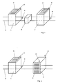
- FIG. 1 shows a first exemplary embodiment of a modulator device for Modulation of unpolarized light in a perspective view.
- the modulator device comprises two Bragg modulators 1 and 2, which by means of a crystal, for. B. from LiNbO 3 , the generation of a diffraction grating on the basis of domain inversion by electrical control.
- the Bragg modulators are each provided on two opposing surfaces with comb-shaped electrodes 3, which can be supplied with an electrical voltage via connections 4.
- the grid arrangement and orientation of the diffraction gratings of the Bragg modulators 1, 2 are predetermined by the electrode arrangement.
- Fig. 1 there are the grids of the two in a row arranged Bragg modulators 1 and 2 oriented parallel to each other.
- everyone Bragg modulator 1,2, however, has a diffractive grating only in one polarization plane.
- the first Bragg modulator 1 is therefore used in the unpolarized one Light is one of the possible polarization planes and a corresponding one Diffraction causes only one of these excellent levels of polarization assigned portion of the incident light 5 is affected.
- a ⁇ / 2 plate 6 is arranged, which the light 5 about its beam axis in view rotates by 90 ° on its polarization planes or directions.
- the Bragg modulators 1, 2 arranged one behind the other with their gratings parallel to one another are aligned, therefore acts after the rotation of the light 5 by the ⁇ / 2 - plate 6 of the second Bragg modulator 2 in the second plane of polarization Light 5, which to the first distinguished by the first Bragg modulator 1 Polarization plane of the light 5 is orthogonal or rotated by 90 °.
- FIG. 3 shows a top view of the modulator device according to FIG. 1.
- the two Bragg - Modulators 1, 2 are oriented towards one another and in particular towards light 5 in such a way that the light 5 when entering the respective Bragg modulator 1 or 2, the so-called Bragg condition is met, at which the desired diffraction of the light takes place, which depends on the angle of incidence ⁇ of the light 5.
- each of the two Bragg modulators 1, 2 a light portion 7 or 8 from which light 5 is diffracted, so that the ultimately emerging light beam 9 is modulated accordingly.
- the diffracted light portions 7 and / or 8 are also suitable for use.
Landscapes
- Physics & Mathematics (AREA)
- Nonlinear Science (AREA)
- General Physics & Mathematics (AREA)
- Optics & Photonics (AREA)
- Mechanical Light Control Or Optical Switches (AREA)
- Optical Modulation, Optical Deflection, Nonlinear Optics, Optical Demodulation, Optical Logic Elements (AREA)
Abstract
Description
- Fig. 1
- eine perspektivische Ansicht einer Modulatoreinrichtung in einem ersten Ausführungsbeispiel mit einer λ/2 - Platte,
- Fig. 2
- eine perspektivische Ansicht eines zweiten Ausführungsbeispiels einer Modulatoreinrichtung und
- Fig. 3
- eine Draufsicht auf die Modulatoreinrichtung gemäß Fig. 1.
Claims (5)
- Verfahren zur Modulation, insbesondere Amplitudenmodulation, von Licht mittels wenigstens eines Bragg-Modulators auf der Basis von domäneninvertierbarem Material, insbesondere für die Aufzeichnung eines zu druckenden Produktes, vorzugsweise zur Herstellung von Druckformen, gekennzeichnet durch die Modulation von unpolarisiertem Licht unter Verwendung eines ersten Bragg-Modulators zur Festlegung einer Polarisationsebene in dem unpolarisierten Licht und zur Modulation des dieser Polarisationsebene zuzuordnenden Lichtanteils und durch die Verwendung eines zweiten Bragg-Modulators zur Modulation des Lichtanteils des unpolarisierten Lichtes, welcher der zur Polarisationsebene des ersten Bragg-Modulators orthogonalen Polarisationsebene zuzuordnen ist.
- Vorrichtung zur Modulation, insbesondere Amplitudenmodulation, von Licht, umfassend wenigstens einen Bragg-Modulator auf der Basis von domäneninvertierbarem Material, insbesondere für die Aufzeichnung eines zu druckenden Produktes, vorzugsweise zur Herstellung von Druckformen, gekennzeichnet durch einen ersten Bragg-Modulator (1) zur Festlegung einer Polarisationsebene in einem unpolarisierten Licht (5) und zur Modulation des dieser Polarisationsebene zuzuordnenden Lichtanteils und durch einen zweiten Bragg-Modulator (2) zur Modulation des Lichtanteils des unpolarisierten Lichtes (5), welcher der zur Polarisationsebene des ersten Bragg-Modulators (1) orthogonalen Polarisationsebene zuzuordnen ist.
- Vorrichtung nach Anspruch 2, dadurch gekennzeichnet, daß der erste und der zweite Bragg-Modulator (1, 2) auf dem Lichtweg hintereinander angeordnet sind.
- Vorrichtung nach Anspruch 3, dadurch gekennzeichnet, daß zwischen dem ersten und dem zweiten Bragg-Modulator (1, 2) eine λ /2 - Platte (6) angeordnet ist.
- Vorrichtung nach Anspruch 3, dadurch gekennzeichnet, daß der erste und der zweite Bragg-Modulator (1, 2) mit ihren Gittern um 90° um die Strahlachse des Lichtes verdreht zueinander angeordnet sind.
Applications Claiming Priority (2)
| Application Number | Priority Date | Filing Date | Title |
|---|---|---|---|
| DE10058999 | 2000-11-28 | ||
| DE10058999A DE10058999A1 (de) | 2000-11-28 | 2000-11-28 | Verfahren und Vorrichtung zur Modulation von unpolarisiertem Licht |
Publications (3)
| Publication Number | Publication Date |
|---|---|
| EP1211553A2 true EP1211553A2 (de) | 2002-06-05 |
| EP1211553A3 EP1211553A3 (de) | 2003-08-27 |
| EP1211553B1 EP1211553B1 (de) | 2006-12-27 |
Family
ID=7664940
Family Applications (1)
| Application Number | Title | Priority Date | Filing Date |
|---|---|---|---|
| EP01125612A Expired - Lifetime EP1211553B1 (de) | 2000-11-28 | 2001-10-26 | Verfahren und Vorrichtung zur Modulation von unpolarisiertem Licht |
Country Status (4)
| Country | Link |
|---|---|
| US (1) | US6618183B2 (de) |
| EP (1) | EP1211553B1 (de) |
| JP (1) | JP3574802B2 (de) |
| DE (2) | DE10058999A1 (de) |
Families Citing this family (2)
| Publication number | Priority date | Publication date | Assignee | Title |
|---|---|---|---|---|
| US7016580B1 (en) | 2002-06-25 | 2006-03-21 | Trans Photonics, L.L.C. | Grating- and polymer-based optical attenuators and modulators |
| US9545785B2 (en) | 2008-09-12 | 2017-01-17 | J P Imaging Limited | Method of printing using a reimageable printing plate with an aluminum oxide surface |
Family Cites Families (14)
| Publication number | Priority date | Publication date | Assignee | Title |
|---|---|---|---|---|
| US3938881A (en) * | 1974-11-25 | 1976-02-17 | Xerox Corporation | Acousto-optic modulation device |
| US4291939A (en) * | 1978-03-24 | 1981-09-29 | The United States Of America As Represented By The Secretary Of The Navy | Polarization-independent optical switches/modulators |
| US5251058A (en) * | 1989-10-13 | 1993-10-05 | Xerox Corporation | Multiple beam exposure control |
| JPH0588123A (ja) * | 1991-09-30 | 1993-04-09 | Hikari Keisoku Gijutsu Kaihatsu Kk | 可変波長フイルタ |
| US5363228A (en) * | 1993-03-05 | 1994-11-08 | General Electric Company | Optical device with spatial light modulators for switching arbitrarily polarized light |
| US5627666A (en) * | 1994-07-27 | 1997-05-06 | Board Of Regents Of The University Of Colorado | Liquid crystal phase modulator using cholesteric circular polarizers |
| JP3430756B2 (ja) * | 1995-12-14 | 2003-07-28 | 富士ゼロックス株式会社 | 光走査素子及び画像形成装置 |
| JP3410287B2 (ja) * | 1996-04-11 | 2003-05-26 | Kddi株式会社 | 光スイッチ |
| DE19643489C1 (de) | 1996-10-22 | 1998-05-07 | Fraunhofer Ges Forschung | Bragg-Modulator |
| JPH10246875A (ja) * | 1997-03-04 | 1998-09-14 | Ando Electric Co Ltd | 音響光学変調器 |
| US6016216A (en) * | 1997-05-17 | 2000-01-18 | Aurora Photonics, Inc. | Polarization-independent acousto-optic tunable filter |
| JPH1184324A (ja) * | 1997-09-05 | 1999-03-26 | Fujitsu Ltd | 波長分割多重における光変調のための方法、装置及びシステム |
| DE19840926B4 (de) | 1998-09-08 | 2013-07-11 | Hell Gravure Systems Gmbh & Co. Kg | Anordnung zur Materialbearbeitung mittels Laserstrahlen und deren Verwendung |
| US20020159151A1 (en) * | 2001-02-26 | 2002-10-31 | Li Jim W. | Optical interleaver using mach-zehnder interferometry |
-
2000
- 2000-11-28 DE DE10058999A patent/DE10058999A1/de not_active Withdrawn
-
2001
- 2001-10-26 DE DE50111724T patent/DE50111724D1/de not_active Expired - Lifetime
- 2001-10-26 EP EP01125612A patent/EP1211553B1/de not_active Expired - Lifetime
- 2001-10-30 US US10/021,326 patent/US6618183B2/en not_active Expired - Fee Related
- 2001-11-27 JP JP2001361431A patent/JP3574802B2/ja not_active Expired - Lifetime
Also Published As
| Publication number | Publication date |
|---|---|
| US6618183B2 (en) | 2003-09-09 |
| JP3574802B2 (ja) | 2004-10-06 |
| US20020063942A1 (en) | 2002-05-30 |
| EP1211553B1 (de) | 2006-12-27 |
| EP1211553A3 (de) | 2003-08-27 |
| DE50111724D1 (de) | 2007-02-08 |
| JP2002207199A (ja) | 2002-07-26 |
| DE10058999A1 (de) | 2002-05-29 |
Similar Documents
| Publication | Publication Date | Title |
|---|---|---|
| EP2908168B1 (de) | Erzeugung von Frequenzkämmen und sinc-förmigen Nyquist-Pulsefolgen großer Bandbreite und abstimmbarer Repetitionsrate | |
| DE2918283A1 (de) | Vorrichtung zur optischen zerhackung eines laserstrahls | |
| DE102014203925B4 (de) | Elektro-optischer Modulator und Verfahren zum Herstellen eines elektro-optischen Modulators | |
| DE1639269B2 (de) | Vorrichtung zur steuerbaren Ablenkung eines mehrere Wellenlängen enthaltenden Lichtstrahls | |
| DE3013498A1 (de) | Optischer modulator sowie laser-graviervorrichtung mit einem derartigen modulator | |
| DE2321211B2 (de) | Strahlablenker mit piezoelektrisch angetriebenen schwenkbaren Spiegeln | |
| WO2012084752A1 (de) | Lichtmodulationseinrichtung | |
| EP1920387B1 (de) | Vorrichtung zur optischen aufspaltung und modulation von elektromagnetischer strahlung | |
| EP1211553B1 (de) | Verfahren und Vorrichtung zur Modulation von unpolarisiertem Licht | |
| DE2159900B2 (de) | Akustische Lichtablenkeinrichtung | |
| DE60030795T2 (de) | Modulator für optisches Drucken | |
| DE102009011599B4 (de) | Oszillator-Verstärker-Anordnungen mit Amplituden-Einstellung | |
| DE102006040843B4 (de) | Vorrichtung zur optischen Aufspaltung und Modulation von elektromagnetischer Strahlung | |
| DE2033965B2 (de) | Digitale lichtablenkvorrichtung | |
| EP3667390B1 (de) | Verfahren und signalgenerator zum ansteuern eines akustooptischen elements | |
| DE102015213468A1 (de) | Strahlmodulator mit Frequenzkonversion sowie zugehöriges Verfahren und Laserbearbeitungsmaschine | |
| DE102016125630B4 (de) | Optische Anordnung und Verfahren zur Beeinflussung der Strahlrichtung mindestens eines Lichtstrahls | |
| DE102006029035B4 (de) | Vorrichtung und Verfahren zur Herstellung und Detektion in Amplitude, Phase und Polarisation geformter Laserpulse | |
| DE3417140A1 (de) | Akusto-optische einrichtung | |
| DE10142255B4 (de) | Anordnung zur transversalen elektro-optischen Amplituden- oder Phasen-Modulation von polarisiertem Laserlicht | |
| DE3688448T2 (de) | Elimination von feldinduzierten instabilitäten in elektrooptischen modulatoren. | |
| DE4331204C2 (de) | Optischer Pulsgenerator | |
| DE2136060C3 (de) | Steuerbare digitale Lichtablenkvorrichtung | |
| WO2021105021A1 (de) | Bereitstellen eines transienten gitters | |
| DE1639267C3 (de) | Achromatischer Lichtablenker |
Legal Events
| Date | Code | Title | Description |
|---|---|---|---|
| PUAI | Public reference made under article 153(3) epc to a published international application that has entered the european phase |
Free format text: ORIGINAL CODE: 0009012 |
|
| AK | Designated contracting states |
Kind code of ref document: A2 Designated state(s): AT BE CH CY DE DK ES FI FR GB GR IE IT LI LU MC NL PT SE TR |
|
| AX | Request for extension of the european patent |
Free format text: AL;LT;LV;MK;RO;SI |
|
| PUAL | Search report despatched |
Free format text: ORIGINAL CODE: 0009013 |
|
| AK | Designated contracting states |
Designated state(s): AT BE CH CY DE DK ES FI FR GB GR IE IT LI LU MC NL PT SE TR |
|
| AX | Request for extension of the european patent |
Extension state: AL LT LV MK RO SI |
|
| 17P | Request for examination filed |
Effective date: 20040227 |
|
| AKX | Designation fees paid |
Designated state(s): DE FR GB IT |
|
| GRAP | Despatch of communication of intention to grant a patent |
Free format text: ORIGINAL CODE: EPIDOSNIGR1 |
|
| GRAS | Grant fee paid |
Free format text: ORIGINAL CODE: EPIDOSNIGR3 |
|
| GRAA | (expected) grant |
Free format text: ORIGINAL CODE: 0009210 |
|
| AK | Designated contracting states |
Kind code of ref document: B1 Designated state(s): DE FR GB IT |
|
| REG | Reference to a national code |
Ref country code: GB Ref legal event code: FG4D Free format text: NOT ENGLISH |
|
| REF | Corresponds to: |
Ref document number: 50111724 Country of ref document: DE Date of ref document: 20070208 Kind code of ref document: P |
|
| GBT | Gb: translation of ep patent filed (gb section 77(6)(a)/1977) |
Effective date: 20070315 |
|
| ET | Fr: translation filed | ||
| PLBE | No opposition filed within time limit |
Free format text: ORIGINAL CODE: 0009261 |
|
| STAA | Information on the status of an ep patent application or granted ep patent |
Free format text: STATUS: NO OPPOSITION FILED WITHIN TIME LIMIT |
|
| 26N | No opposition filed |
Effective date: 20070928 |
|
| PGFP | Annual fee paid to national office [announced via postgrant information from national office to epo] |
Ref country code: FR Payment date: 20091117 Year of fee payment: 9 Ref country code: GB Payment date: 20091026 Year of fee payment: 9 Ref country code: IT Payment date: 20091022 Year of fee payment: 9 |
|
| PGFP | Annual fee paid to national office [announced via postgrant information from national office to epo] |
Ref country code: DE Payment date: 20101130 Year of fee payment: 10 |
|
| GBPC | Gb: european patent ceased through non-payment of renewal fee |
Effective date: 20101026 |
|
| PG25 | Lapsed in a contracting state [announced via postgrant information from national office to epo] |
Ref country code: FR Free format text: LAPSE BECAUSE OF NON-PAYMENT OF DUE FEES Effective date: 20101102 |
|
| REG | Reference to a national code |
Ref country code: FR Ref legal event code: ST Effective date: 20110630 |
|
| PG25 | Lapsed in a contracting state [announced via postgrant information from national office to epo] |
Ref country code: GB Free format text: LAPSE BECAUSE OF NON-PAYMENT OF DUE FEES Effective date: 20101026 |
|
| PG25 | Lapsed in a contracting state [announced via postgrant information from national office to epo] |
Ref country code: IT Free format text: LAPSE BECAUSE OF NON-PAYMENT OF DUE FEES Effective date: 20101026 |
|
| PG25 | Lapsed in a contracting state [announced via postgrant information from national office to epo] |
Ref country code: DE Free format text: LAPSE BECAUSE OF NON-PAYMENT OF DUE FEES Effective date: 20120501 |
|
| REG | Reference to a national code |
Ref country code: DE Ref legal event code: R119 Ref document number: 50111724 Country of ref document: DE Effective date: 20120501 |