EP3667390B1 - Verfahren und signalgenerator zum ansteuern eines akustooptischen elements - Google Patents
Verfahren und signalgenerator zum ansteuern eines akustooptischen elements Download PDFInfo
- Publication number
- EP3667390B1 EP3667390B1 EP19215791.5A EP19215791A EP3667390B1 EP 3667390 B1 EP3667390 B1 EP 3667390B1 EP 19215791 A EP19215791 A EP 19215791A EP 3667390 B1 EP3667390 B1 EP 3667390B1
- Authority
- EP
- European Patent Office
- Prior art keywords
- acousto
- optic
- crystal
- frequency
- driving
- Prior art date
- Legal status (The legal status is an assumption and is not a legal conclusion. Google has not performed a legal analysis and makes no representation as to the accuracy of the status listed.)
- Active
Links
Images


Classifications
-
- H—ELECTRICITY
- H03—ELECTRONIC CIRCUITRY
- H03K—PULSE TECHNIQUE
- H03K5/00—Manipulating of pulses not covered by one of the other main groups of this subclass
- H03K5/153—Arrangements in which a pulse is delivered at the instant when a predetermined characteristic of an input signal is present or at a fixed time interval after this instant
- H03K5/1534—Transition or edge detectors
-
- G—PHYSICS
- G02—OPTICS
- G02B—OPTICAL ELEMENTS, SYSTEMS OR APPARATUS
- G02B21/00—Microscopes
- G02B21/0004—Microscopes specially adapted for specific applications
- G02B21/002—Scanning microscopes
- G02B21/0024—Confocal scanning microscopes (CSOMs) or confocal "macroscopes"; Accessories which are not restricted to use with CSOMs, e.g. sample holders
- G02B21/0032—Optical details of illumination, e.g. light-sources, pinholes, beam splitters, slits, fibers
-
- G—PHYSICS
- G02—OPTICS
- G02F—OPTICAL DEVICES OR ARRANGEMENTS FOR THE CONTROL OF LIGHT BY MODIFICATION OF THE OPTICAL PROPERTIES OF THE MEDIA OF THE ELEMENTS INVOLVED THEREIN; NON-LINEAR OPTICS; FREQUENCY-CHANGING OF LIGHT; OPTICAL LOGIC ELEMENTS; OPTICAL ANALOGUE/DIGITAL CONVERTERS
- G02F1/00—Devices or arrangements for the control of the intensity, colour, phase, polarisation or direction of light arriving from an independent light source, e.g. switching, gating or modulating; Non-linear optics
- G02F1/29—Devices or arrangements for the control of the intensity, colour, phase, polarisation or direction of light arriving from an independent light source, e.g. switching, gating or modulating; Non-linear optics for the control of the position or the direction of light beams, i.e. deflection
- G02F1/33—Acousto-optical deflection devices
-
- G—PHYSICS
- G02—OPTICS
- G02B—OPTICAL ELEMENTS, SYSTEMS OR APPARATUS
- G02B21/00—Microscopes
- G02B21/0004—Microscopes specially adapted for specific applications
- G02B21/002—Scanning microscopes
- G02B21/0024—Confocal scanning microscopes (CSOMs) or confocal "macroscopes"; Accessories which are not restricted to use with CSOMs, e.g. sample holders
- G02B21/0052—Optical details of the image generation
- G02B21/0076—Optical details of the image generation arrangements using fluorescence or luminescence
-
- G—PHYSICS
- G02—OPTICS
- G02F—OPTICAL DEVICES OR ARRANGEMENTS FOR THE CONTROL OF LIGHT BY MODIFICATION OF THE OPTICAL PROPERTIES OF THE MEDIA OF THE ELEMENTS INVOLVED THEREIN; NON-LINEAR OPTICS; FREQUENCY-CHANGING OF LIGHT; OPTICAL LOGIC ELEMENTS; OPTICAL ANALOGUE/DIGITAL CONVERTERS
- G02F1/00—Devices or arrangements for the control of the intensity, colour, phase, polarisation or direction of light arriving from an independent light source, e.g. switching, gating or modulating; Non-linear optics
- G02F1/01—Devices or arrangements for the control of the intensity, colour, phase, polarisation or direction of light arriving from an independent light source, e.g. switching, gating or modulating; Non-linear optics for the control of the intensity, phase, polarisation or colour
- G02F1/11—Devices or arrangements for the control of the intensity, colour, phase, polarisation or direction of light arriving from an independent light source, e.g. switching, gating or modulating; Non-linear optics for the control of the intensity, phase, polarisation or colour based on acousto-optical elements, e.g. using variable diffraction by sound or like mechanical waves
- G02F1/113—Circuit or control arrangements
-
- H—ELECTRICITY
- H01—ELECTRIC ELEMENTS
- H01S—DEVICES USING THE PROCESS OF LIGHT AMPLIFICATION BY STIMULATED EMISSION OF RADIATION [LASER] TO AMPLIFY OR GENERATE LIGHT; DEVICES USING STIMULATED EMISSION OF ELECTROMAGNETIC RADIATION IN WAVE RANGES OTHER THAN OPTICAL
- H01S3/00—Lasers, i.e. devices using stimulated emission of electromagnetic radiation in the infrared, visible or ultraviolet wave range
- H01S3/005—Optical devices external to the laser cavity, specially adapted for lasers, e.g. for homogenisation of the beam or for manipulating laser pulses, e.g. pulse shaping
- H01S3/0057—Temporal shaping, e.g. pulse compression, frequency chirping
-
- G—PHYSICS
- G02—OPTICS
- G02B—OPTICAL ELEMENTS, SYSTEMS OR APPARATUS
- G02B21/00—Microscopes
- G02B21/0004—Microscopes specially adapted for specific applications
- G02B21/002—Scanning microscopes
- G02B21/0024—Confocal scanning microscopes (CSOMs) or confocal "macroscopes"; Accessories which are not restricted to use with CSOMs, e.g. sample holders
- G02B21/0052—Optical details of the image generation
- G02B21/0064—Optical details of the image generation multi-spectral or wavelength-selective arrangements, e.g. wavelength fan-out, chromatic profiling
Definitions
- the present invention relates to a method and a signal generator for controlling an acousto-optical element, an arrangement comprising such a signal generator and an acousto-optical element, and a microscope with such an arrangement.
- excitation light with one or more specified wavelengths.
- one or more excitation light beams which usually have to have specified spectral properties, may be necessary.
- wavelength-selective elements based on the acousto-optical effect can be used.
- acousto-optical elements usually have a so-called acousto-optical crystal, which is set into vibration by an acoustic signal generator, also known as a transducer.
- a transducer usually has a piezoelectric material and two or more electrodes that contact this material.
- the piezoelectric material is excited to vibrate, so that an acoustic wave can be created that passes through the crystal.
- Acousto-optical crystals are characterized by the fact that the resulting sound wave changes the optical properties of the crystal.
- acousto-optical elements which can also be used advantageously within the scope of the invention, are acousto-optical tunable filters (AOTF), acousto-optical modulators (AOM), acousto-optical deflectors (AOD), acousto-optical beam splitters (AOBS) and acousto-optical beam combiners (AOBM).
- AOTF acousto-optical tunable filters
- AOM acousto-optical modulators
- AOD acousto-optical deflectors
- AOBS acousto-optical beam splitters
- AOBM acousto-optical beam combiners
- the high-frequency electrical signals for the converter are usually generated in a frequency generator (for example a voltage-controlled oscillator (VCO), a phase-locked loop (PLL), or a synthesizer using the DDS method (direct digital synthesis)) and amplified using a high-frequency amplifier so that the amplitude is large enough to make the crystal oscillate.
- a frequency generator for example a voltage-controlled oscillator (VCO), a phase-locked loop (PLL), or a synthesizer using the DDS method (direct digital synthesis)
- VCO voltage-controlled oscillator
- PLL phase-locked loop
- DDS method direct digital synthesis
- the passband width of acousto-optical modulators can be varied by structural measures such as the design of the crystal geometry and/or the transducer and by the curve shape of the control signal.
- structural measures such as the design of the crystal geometry and/or the transducer and by the curve shape of the control signal.
- several closely spaced frequencies can be superimposed and fed into the crystal, which causes the individual passbands to overlap to form a larger passband.
- the disadvantage of these methods is that the broadening of the passband curve cannot be changed in the constructive solution. If different passband widths are required, the crystals must be exchanged. Furthermore, the passband widths in the entire spectral range of the crystal are predetermined by the geometry. With the superposition solution, high peak powers arise that must be processed by the RF amplifier used. To ensure that the amplifier does not produce mixed products due to non-linear behavior, its linear range must be very large. This means that the amplifier must deliver a significantly higher peak power compared to the average power. This makes the amplifier significantly more expensive. If the differences between the individual frequencies are unfavorable to one another, mixed products can arise, which, for example, when using a white light laser as a light source, leads to unwanted colors being switched on.
- GB 2 427 034 A discloses an acousto-optical crystal and a piezoelectric transducer for displacing the acousto-optical crystal in mechanical vibrations.
- the acousto-optical crystal is controlled with two different control frequencies, whereby the grating generated by density fluctuations can have different grating spacings at the same time.
- WO 2017/207664 A1 discloses the control of an acousto-optical crystal with two different frequencies. Different pulsed light beams can hit different excitation frequencies of the acousto-optical crystal.
- EN 10 2013 201 968 A1 discloses an acousto-optical deflector, whereby two oscillation frequencies can be generated simultaneously in the crystal.
- WO 2018/197546 A1 discloses a method for controlling an acousto-optical element with a control signal that is generated by means of a DDS method with a signal value sequence that is composed of at least two frequency components.
- JP 2000 149337 A shows an exposure device for optical disks in which laser beams are focused on a rotating exposure master disk on which a photoresist is applied in order to expose a row of pits or a groove.
- An acousto-optical element is arranged in the beam path.
- Several high-frequency signal generators are arranged, which apply drive signals with different frequencies to the acousto-optical element.
- a high-speed switching element and a pulse signal generator are provided, which sequentially and repeatedly apply one of the drive signals generated by the high-frequency signal generators to the acousto-optical element.
- the invention is based on the measure of exposing an acousto-optical crystal to a sound wave whose frequency varies so quickly over time that a lattice with several lattice constants is effectively formed.
- a sound wave in an acousto-optical crystal leads to a lattice structure whose lattice constant depends on the frequency of the sound and the speed of sound in the crystal. If a laser beam passes through this lattice structure and the dimensions of the structure and the wavelength of the light match, part of the laser light is deflected by a diffraction process. Some light is continuously deflected along the beam path in the sound field. If you look at the amount of deflected light along a small part of the beam path in the sound field, this is correlated with the sound power and thus the shape of the lattice created by the sound. The amplitude and thus the shape of the lattice thus determines the amount of deflected light. The maximum amount of deflected light is reached when all of the light that can be deflected in principle has been deflected at the point where the light beam leaves the sound field.
- the sound-generating frequency is not constant, but alternates between several different values around a center frequency, then a lattice structure is created with lattice constants that change in zones. These several different values are also referred to below as the center frequency spectrum.
- the center frequency itself can, but does not have to, be part of the center frequency spectrum.
- Each of these zones deflects light from a specific wavelength range. Since the light beam passes through several zones in succession, some light of a different wavelength is deflected in each zone. In order to deflect the same amount of light as in the monochromatic case, the grating intensity and thus the sound power can be somewhat higher. If the frequencies are switched quickly enough, there are always several zones with the same lattice constant in the crystal. This ensures that the spectrum of the deflected light is constant over time.
- the control frequency can alternately assume several different values around a center frequency during a passage of a mechanical oscillation wave through the acousto-optical crystal
- the switching takes place taking into account the crystal expansion and the speed of sound in the crystal.
- These values determine the time that a mechanical oscillation wave needs to pass through the crystal and during which the frequency of the control signal must assume at least two different values at least once. Preferably, however, it assumes the at least two different values several times during this time.
- control frequency takes on two to eight different values. This is practical because different wavelength ranges of light can be deflected in this way, but at the same time the switching can take place quickly enough so that the intensity of the deflected light is sufficiently high.
- the several different values are in a bandwidth of 50 kHz - 1 MHz around the center frequency.
- control signal has a constant amplitude for each control frequency.
- different amplitudes for the different control frequencies are also conceivable.
- it can be advantageous It may be necessary to apply a higher amplitude at higher frequencies due to the damping behavior.
- a suitable type of switching should be jump-free, i.e. the curve of the control signal for the sound generation should be continuous. Otherwise, undesirable harmonics would be generated. Furthermore, a frequency should be present for at least one complete period, preferably a plurality of complete periods, in order to build up a clear grid structure.
- the at least one control frequency is periodically changed so quickly that a light beam that enters the acousto-optical crystal - in particular not perpendicular to the mechanical oscillation wave - hits the same grating spacing at least twice. This ensures that the spectrum of the deflected light is constant over time.
- the at least one control frequency is periodically changed so quickly that the light beam hits the same grating spacing at least three or more times. In this way, the uniformity of the light deflection can be further improved.
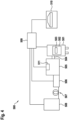
- Figure 1 shows schematically an arrangement 100 according to a preferred embodiment of the invention.
- the arrangement 100 comprises a signal generator 101. This serves to control an acousto-optical element 200, which has an acousto-optical crystal 202 and a piezoelectric converter 201 for setting the crystal 202 into mechanical vibrations.
- the acousto-optical element serves to influence light in a desired manner, e.g. as an AOTF.
- the mechanical vibrations cause density fluctuations in the crystal, which function as an optical grating, as in Figure 3 indicated.
- the signal generator 101 is configured to control the piezoelectric transducer 201 with a control signal 300 having at least one control frequency f, wherein the at least one control frequency f alternately assumes several different values around a center frequency during a passage of a mechanical oscillation wave 301 through the acousto-optical crystal 202, so that a grating generated by density fluctuations in the acousto-optical crystal 202 simultaneously has different grating spacings.
- Figure 2 shows an example of such a control signal 300.
- the control frequency f alternately takes on two different values f 1 , f 2 .
- it takes on the value f 1 between time t 0 and time t 1 , the value f 2 between t 1 and t 2 , the value f 1 between t 2 and t 3 and the value f 2 between t 3 and t 4.
- the curve of the control signal 300 is nevertheless continuous and jump-free.
- the control frequency f of the control signal 300 is always constant for at least one oscillation period, more precisely in this example exactly four oscillation periods.
- FIG. 3 shows an acousto-optical element 200 which is controlled according to an embodiment of a method according to the invention.
- the acousto-optical element 200 has an acousto-optical crystal 202 and a piezoelectric transducer 201 for setting the crystal 202 into mechanical vibrations.
- the piezoelectric transducer 201 is controlled by a control signal 300 with at least one control frequency f, wherein the at least one control frequency f alternately assumes three different values during a passage of a mechanical oscillation wave through the acousto-optical crystal 202.
- a mechanical vibration wave 301 is formed, which continues through the acousto-optical crystal 202 as an acoustic sound wave.
- a lattice structure is created with zone-wise changing lattice constants, whereby Figure 3 the lattice structure is shown for a specific point in time.
- zones are marked with different hatching and are labelled z1, z2, z3, z4, z5, z6, z7, z8, z9, z10, z11 and z12.
- a lattice constant is repeated every three zones.
- zones z1, z4, z7 and z10 as well as zones z2, z5, z8 and z11 as well as zones z3, z6, z9 and z12 each have the same lattice constant. This is shown in the figure by the fact that zones with the same lattice constant each have the same hatching.
- the acousto-optical crystal is used to deflect light rays. If a light ray passes through this lattice structure and the dimensions of the structure and the wavelength of the light match, part of the light ray is deflected by a diffraction process. Each of these zones deflects light of a specific wavelength range. Since the light ray passes through several zones z1, ..., z12 in succession, some light of a different wavelength is deflected in each zone. An incident light ray is shown and labeled 401. A non-deflected light ray is labeled 402. A deflected light ray is labeled 403.
- the at least one control frequency 300 is periodically changed so quickly that a light beam 401 that is incident on the acousto-optical crystal 202 hits the same grating spacing at least twice. This is the case with the For the incident light beam 401 shown, this is the case for zones z6 and z9 or z7 and z10, for example.
- FIG 4 shows a schematic of a confocal microscope with typical components.
- 500 denotes the overall system.
- the confocal scanning and detection unit is denoted by 505.
- the associated illumination device is denoted by 506.
- the 508 is a laser light source that is connected to the illumination device 506 via an illumination fiber 507. If desired, the laser light is influenced in the illumination device 506 by means of an acousto-optical element.
- a control unit 509 is connected to the individual components 508, 506, 505 and 501 via corresponding connecting lines.
- a computer with control and display programs is designated 510; it is also connected to the control unit 509.
- a classic confocal beam path is arranged within the confocal scanning and detection unit 505, which is constructed in a known manner with a single pinhole and a beam scanner, for example a mirror scanner.
- a beam path is located within the confocal scanning and detection unit 505, in which the sample is illuminated simultaneously with one or more illumination points or with illumination points extending in one direction. Accordingly, the photons to be detected For example, using a geometric arrangement of pinholes.
- the sample 503 to be examined is illuminated via a microscope optics and imaged via the same microscope optics in particular onto a sensor arrangement 511, which, depending on the embodiment of the confocal scanning and detection unit 505, consists of a photomultiplier or an array of photomultipliers.
- a sensor arrangement 511 which, depending on the embodiment of the confocal scanning and detection unit 505, consists of a photomultiplier or an array of photomultipliers.
- the functionality of a Figure 4 The system 500 shown is well known per se and will therefore not be explained here.
Landscapes
- Physics & Mathematics (AREA)
- Nonlinear Science (AREA)
- Optics & Photonics (AREA)
- General Physics & Mathematics (AREA)
- Electromagnetism (AREA)
- Chemical & Material Sciences (AREA)
- Analytical Chemistry (AREA)
- Engineering & Computer Science (AREA)
- Plasma & Fusion (AREA)
- Optical Modulation, Optical Deflection, Nonlinear Optics, Optical Demodulation, Optical Logic Elements (AREA)
- Microscoopes, Condenser (AREA)
Description
- Die vorliegende Erfindung betrifft ein Verfahren und einen Signalgenerator zum Ansteuern eines akustooptischen Elements, eine Anordnung aus einem solchen Signalgenerator und einem akustooptischen Element sowie ein Mikroskop mit einer solchen Anordnung.
- Eine wesentliche Herausforderung in Bereichen der Mikroskopie ist, unabhängig vom eingesetzten Verfahren, die Bereitstellung von Anregungslicht mit einer oder mehreren vorgegebenen Wellenlängen. Je nach Art des Mikroskopieverfahrens und/oder nach Art der Probe können ein oder mehrere Anregungslichtstrahlen, welche in der Regel vorgegebene spektrale Eigenschaften aufweisen müssen, notwendig sein.
- Beispielsweise ist es auf dem Gebiet der Fluoreszenzmikroskopie wichtig, Licht mit derjenigen Wellenlänge zu verwenden, die die Fluoreszenz anregt. Verschiedene Wellenlängen werden insbesondere dann gebraucht, wenn die Probe Fluoreszenzstoffe mit unterschiedlichen Emissionswellenlängen enthält.
- Auf dem Gebiet der konfokalen Rastermikroskopie ist es von besonderem Interesse, die Intensitäten für bestimmte Wellenlängen anzupassen oder bestimmte Wellenlängen ein- oder auszuschalten.
- Zu diesem Zweck können wellenlängenselektive Elemente zum Einsatz kommen, welche auf dem akustooptischen Effekt basieren. Derartige akustooptische Elemente weisen in der Regel einen sogenannten akustooptischen Kristall auf, welcher mittels eines akustischen Signalgebers, auch als Wandler oder "Transducer" bezeichnet, in Schwingung versetzt wird. In der Regel weist ein derartiger Wandler ein piezoelektrisches Material sowie zwei oder mehrere dieses Material kontaktierende Elektroden auf. Durch elektrisches Beschalten der Elektroden mit Hochfrequenzen, die typischerweise im Bereich zwischen 10 MHz und wenigen GHz liegen, wird das piezoelektrische Material zum Schwingen angeregt, so dass eine akustische Welle entstehen kann, die den Kristall durchläuft. Akustooptische Kristalle zeichnen sich dadurch aus, dass die entstehende Schallwelle die optischen Eigenschaften des Kristalls verändert.
- Beispiele für solche akustooptischen Elemente, die auch im Rahmen der Erfindung vorteilhaft verwendbar sind, sind akustooptische abstimmbare Filter (AOTF), akustooptische Modulatoren (AOM), akustooptische Ablenker bzw. Deflektoren (AOD), akustooptische Strahlteiler (AOBS) und akustooptische Strahlvereiniger (AOBM).
- Eine besondere Herausforderung bei der Verwendung von akustooptischen Elementen stellt deren Ansteuerung dar. Die hochfrequenten elektrischen Signale für den Wandler werden üblicherweise in einem Frequenzgenerator (beispielsweise ein spannungsgesteuerter Oszillator (englisch voltage-controlled oscillator, VCO), eine Phasenregelschleife (englisch phase-locked loop, PLL), oder ein Synthesizer nach dem DDS-Verfahren (direkte digitale Synthese (englisch direct digital synthesis)) erzeugt und mittels Hochfrequenzverstärkers so verstärkt, dass die Amplitude genügend groß ist, um den Kristall in Schwingung zu versetzen. Bei mehreren gleichzeitig angelegten, unterschiedlichen Ansteuerfrequenzen können Lichtstrahlen mehrerer Wellenlängen gleichzeitig (beispielsweise bei einem AOTF, AOBS, AOBM, AOM) beziehungsweise eine Wellenlänge eines einfallenden Lichtstrahls in mehrere Lichtstrahlen verschiedener Richtungen gleichzeitig (beispielsweise bei einem AOD) abgelenkt werden.
- Die Durchlassbandbreite akustooptischer Modulatoren kann zum einem durch konstruktive Maßnahmen wie die Ausgestaltung der Kristallgeometrie und/oder des Transducers und zum anderen durch die Kurvenform des Ansteuersignals variiert werden. Beispielsweise können im zweiten Fall mehrere eng zusammen liegende Frequenzen überlagert und in den Kristall eingespeist werden, was eine Überlappung der einzelnen Durchlassbereiche zu einem größeren Durchlassbereich bewirkt.
- Nachteilig an diesen Methoden ist, dass bei der konstruktiven Lösung die Verbreiterung der Durchlasskurve nicht veränderbar ist. Wenn verschiedene Durchlassbreiten gewünscht sind, müssen die Kristalle getauscht werden. Weiterhin sind die Durchlassbreiten im gesamten Spektralbereich des Kristalls durch die Geometrie vorgegeben. Bei der Überlagerungslösung entstehen durch hohe Spitzenleistungen, die von dem verwendeten HF-Verstärker verarbeitet werden müssen. Damit der Verstärker durch nichtlineares Verhalten keine Mischprodukte produziert, muss sein linearer Bereich sehr groß sein. Das bedeutet, dass der Verstärker im Vergleich zur mittleren Leistung eine erheblich höhere Spitzenleistung liefern muss. Dies verteuert den Verstärker erheblich. Wenn die Differenzen der Einzelfrequenzen ungünstig zueinander liegen, können Mischprodukte entstehen, was z.B. bei der Verwendung eines Weißlichtlasers als Lichtquelle dazu führt, dass auch unerwünschte Farben eingeschaltet werden.
-
GB 2 427 034 A -
WO 2017/207664 A1 offenbart eine Ansteuerung eines akustooptischen Kristalls mit zwei verschiedenen Frequenzen. Dabei können verschiedene gepulste Lichtstrahlen auf verschiedene Anregungsfrequenzen des akustooptischen Kristalls treffen. -
DE 10 2013 201 968 A1 offenbart einen akustooptischen Deflektor, wobei zwei Schwingungsfrequenzen gleichzeitig im Kristall erzeugt werden können. -
WO 2018/197546 A1 offenbart ein Verfahren zur Ansteuerung eines akustooptischen Elements mit einem Ansteuersignal, das mittels eines DDS-Verfahrens mit einer Signalwertfolge, die sich aus mindestens zwei Frequenzkomponenten zusammensetzt, erzeugt wird. -
JP 2000 149337 A - Erfindungsgemäß werden ein Verfahren und ein Signalgenerator zum Ansteuern eines akustooptischen Elements, eine Anordnung aus einem solchen Signalgenerator und einem akustooptischen Element sowie ein Mikroskop mit einer solchen Anordnung mit den Merkmalen der unabhängigen Patentansprüche vorgeschlagen. Vorteilhafte Ausgestaltungen sind Gegenstand der Unteransprüche sowie der nachfolgenden Beschreibung.
- Die Erfindung basiert auf der Maßnahme, einen akustooptischen Kristall mit einer Schallwelle zu beaufschlagen, deren Frequenz zeitlich so schnell variiert, dass sich effektiv ein Gitter mit mehreren Gitterkonstanten ausbildet.
- Bekanntermaßen führt eine Schallwelle in einem akustooptischen Kristall zu einer Gitterstruktur, deren Gitterkonstante von der Frequenz des Schalls und der Schallgeschwindigkeit im Kristall abhängt. Durchläuft ein Laserstrahl diese Gitterstruktur und passen die Dimensionen der Struktur und die Wellenlänge des Lichtes zusammen, wird ein Teil des Laserlichtes durch einen Beugungsprozess abgelenkt. Längs des Strahlverlaufes im Schallfeld wird kontinuierlich etwas Licht abgelenkt. Betrachtet man die Menge des abgelenkten Lichtes längs eines kleinen Teils des Strahlverlaufes im Schallfeld, so ist diese korreliert mit der Schalleistung und damit der Ausprägung des durch den Schall erzeugten Gitters. Die Amplitude und damit die Ausprägung des Gitters bestimmt somit die Menge des abgelenkten Lichtes. Das Maximum der Menge des abgelenkten Lichtes ist dann erreicht, wenn von der prinzipiell ablenkbaren Menge an der Stelle, an der der Lichtstrahl das Schallfeld verlässt, alles Licht abgelenkt wurde.
- Wenn die schallerzeugende Frequenz nicht konstant ist, sondern abwechselnd mehrere verschiedene Werte um eine Mittenfrequenz annimmt, dann entsteht eine Gitterstruktur mit zonenweise wechselnden Gitterkonstanten. Diese mehreren verschiedenen Werte werden im Folgenden auch als Mittenfrequenzspektrum bezeichnet. Die Mittenfrequenz selbst kann, muss aber nicht Bestandteil des Mittenfrequenzspektrums sein.
- Jede dieser Zonen lenkt Licht aus einem bestimmten Wellenlängenbereich ab. Da der Lichtstrahl nacheinander mehrere Zonen durchläuft, wird in jeder Zone etwas Licht einer anderen Wellenlänge abgelenkt. Um nun die gleiche Menge an Licht abzulenken wie im monochromatischen Falle, können die Gitterintensität und damit Schalleistung etwas höher sein. Bei einem genügend schnellen Umschalten der Frequenzen existieren immer mehrere Zonen der gleichen Gitterkonstante im Kristall. Es ist dann sichergestellt, dass das Spektrum des abgelenkten Lichtes zeitlich konstant ist.
- Damit die Ansteuerfrequenz während eines Durchlaufs einer mechanischen Schwingungswelle durch den akustooptischen Kristall abwechselnd mehrere verschiedene Werte um eine Mittenfrequenz annehmen kann, erfolgt das Umschalten unter Berücksichtigung der Kristallausdehnung und der Schallgeschwindigkeit im Kristall. Aus diesen Größen ergibt sich die Zeit, die eine mechanische Schwingungswelle zum Durchlaufen des Kristalls benötigt und während der die Frequenz des Ansteuersignals wenigstens einmal wenigstens zwei unterschiedliche Werte annehmen muss. Vorzugsweise nimmt sie jedoch während dessen mehrmals die wenigstens zwei unterschiedlichen Werte an.
- Vorzugsweise nimmt die Ansteuerfrequenz zwei bis acht verschiedene Werte an. Dies ist praktikabel, da auf diese Weise unterschiedliche Wellenlängenbereiche von Licht abgelenkt werden können, gleichzeitig aber die Umschaltung schnell genug erfolgen kann, damit die Intensität des jeweils abgelenkten Lichtes ausreichend groß ist. Vorzugsweise befinden sich die mehreren verschiedenen Werte in einer Bandbreite von 50 kHz - 1 MHz um die Mittenfrequenz.
- Insbesondere weist das Ansteuersignal für jede Ansteuerfrequenz eine konstante Amplitude auf. Jedoch sind auch unterschiedliche Amplituden für die unterschiedlichen Ansteuerfrequenzen denkbar. Insbesondere kann es vorteilhaft sein, bei höheren Frequenzen aufgrund des Dämpfungsverhaltens eine höhere Amplitude anzulegen.
- Weitere Vorteile und Ausgestaltungen der Erfindung ergeben sich aus der Beschreibung und der beiliegenden Zeichnung.
- Eine geeignete Art der Umschaltung sollte sprungfrei sein, d.h. der Kurvenzug des Ansteuersignals der Schallerzeugung sollte kontinuierlich sein. Anderenfalls würden unerwünschte Oberwellen erzeugt. Weiterhin sollte eine Frequenz mindestens eine komplette Periode lang anliegen, vorzugsweise eine Mehrzahl von kompletten Perioden, um eine eindeutige Gitterstruktur aufzubauen.
- Durch das abwechselnde Anlegen von unterschiedlichen Frequenzen ist sichergestellt, dass aus jedem Mittenfrequenzspektrum immer nur eine Frequenz in einem Zeitintervall am Kristall anliegt. Es ist also nicht möglich, mit anderen Frequenzen Intermodulationsprodukte zu bilden. Auch ist es nicht möglich, durch Schwebungen hohe Leistungsspitzen zu erzeugen.
- Vorteilhaft wird die wenigstens eine Ansteuerfrequenz periodisch derart schnell verändert, dass ein Lichtstrahl, der - insbesondere nicht senkrecht zu der mechanischen Schwingungswelle - in den akustooptischen Kristall einfällt, mindestens zweimal auf den gleichen Gitterabstand trifft. Es ist dadurch sichergestellt, dass das Spektrum des abgelenkten Lichtes zeitlich konstant ist. Gemäß der Erfindung wird die wenigstens eine Ansteuerfrequenz periodisch derart schnell verändert, dass der Lichtstrahl mindestens drei oder mehrmals auf den gleichen Gitterabstand trifft. Auf diese Weise kann eine Gleichmäßigkeit der Lichtablenkung noch verbessert werden.
- Da der Kristall Dichtefelder superponieren kann, ist es möglich, dieses Verfahren mit verschiedenen Mittenfrequenzen gleichzeitig im gleichen Kristall anzuwenden. Wenn die Mittenfrequenzen entsprechend weit auseinanderliegen, bleiben obige Vorteile des Verfahrens weitgehend erhalten.
- Es versteht sich, dass die vorstehend genannten und die nachstehend noch zu erläuternden Merkmale nicht nur in der jeweils angegebenen Kombination, sondern auch in anderen Kombinationen oder in Alleinstellung verwendbar sind, ohne den Rahmen der vorliegenden Erfindung zu verlassen.
- Die Erfindung ist anhand eines Ausführungsbeispiels in der Zeichnung schematisch dargestellt und wird im Folgenden unter Bezugnahme auf die Zeichnung beschrieben.
-
- Figur 1
- zeigt eine Anordnung gemäß einer Ausführungsform der Erfindung,
- Figur 2
- zeigt einen Verlauf eines Ansteuersignals für einen piezoelektrischen Wandler gemäß einer Ausführungsform eines erfindungsgemäßen Verfahrens,
- Figur 3
- zeigt ein akustooptisches Element, das gemäß einer Ausführungsform eines erfindungsgemäßen Verfahrens angesteuert wird,
- Figur 4
- zeigt eine Übersicht über die typischen Elemente eines konfokalen Mikroskops in schematischer Ansicht.
-
Figur 1 zeigt schematisch eine Anordnung 100 gemäß einer bevorzugten Ausführungsform der Erfindung. - Die Anordnung 100 umfasst einen Signalgenerator 101. Dieser dient zur Ansteuerung eines akustooptischen Elements 200, welches einen akustooptischen Kristall 202 und einen piezoelektrischen Wandler 201 zur Versetzung des Kristalls 202 in mechanische Schwingungen aufweist. Das akustooptische Element dient zur Beeinflussung von Licht in einer gewünschten Art und Weise, z.B. als AOTF. Die mechanischen Schwingungen bewirken Dichteschwankungen im Kristall, die als optisches Gitter fungieren, wie in
Figur 3 angedeutet. - Der Signalgenerator 101 ist dazu eingerichtet, den piezoelektrischen Wandler 201 mit einem Ansteuersignal 300 mit wenigstens einer Ansteuerfrequenz f anzusteuern, wobei die wenigstens eine Ansteuerfrequenz f während eines Durchlaufs einer mechanischen Schwingungswelle 301 durch den akustooptischen Kristall 202 abwechselnd mehrere verschiedene Werte um eine Mittenfrequenz annimmt, so dass ein durch Dichteschwankungen im akustooptischen Kristall 202 erzeugtes Gitter gleichzeitig verschiedene Gitterabstände aufweist.
-
Figur 2 zeigt beispielhaft ein solches Ansteuersignal 300. Es ist zu sehen, dass die Ansteuerfrequenz f abwechselnd zwei verschiedene Werte f1, f2 annimmt. Sie nimmt insbesondere zwischen Zeitpunkt t0 und Zeitpunkt t1 den Wert f1 an, zwischen t1 und t2 den Wert f2, zwischen t2 und t3 den Wert f1 und zwischen t3 und t4 den Wert f2 an. Obwohl die Werte der Ansteuerfrequenz f1, f2 abwechseln, ist der Kurvenzug des Ansteuersignals 300 dennoch kontinuierlich und sprungfrei. Weiterhin ist zu sehen, dass die Ansteuerfrequenz f des Ansteuersignals 300 immer jeweils wenigstens eine Schwingungsdauer konstant ist, genauer gesagt in diesem Beispiel jeweils genau vier Schwingungsdauern. -
Figur 3 zeigt ein akustooptisches Element 200, das gemäß einer Ausführungsform eines erfindungsgemäßen Verfahrens angesteuert wird. Das akustooptische Element 200 weist einen akustooptischen Kristall 202 und einen piezoelektrischen Wandler 201 zur Versetzung des Kristalls 202 in mechanische Schwingungen auf. Der piezoelektrische Wandler 201 wird mit einem Ansteuersignal 300 mit wenigstens einer Ansteuerfrequenz f angesteuert, wobei die wenigstens eine Ansteuerfrequenz f während eines Durchlaufs einer mechanischen Schwingungswelle durch den akustooptischen Kristall 202 hier abwechselnd drei verschiedene Werte annimmt. - Es bildet sich eine mechanische Schwingungswelle 301 aus, die sich durch den akustooptischen Kristall 202 als akustische Schallwelle fortsetzt. Es entsteht eine Gitterstruktur mit zonenweise wechselnden Gitterkonstanten, wobei in
Figur 3 die Gitterstruktur für einen bestimmten Zeitpunkt dargestellt ist. - Die Zonen sind mit unterschiedlichen Schraffuren gekennzeichnet und mit z1, z2, z3, z4, z5, z6, z7, z8, z9, z10, z11 und z12 bezeichnet. Immer nach drei Zonen wiederholt sich eine Gitterkonstante. Auf diese Weise weisen sowohl Zonen z1, z4, z7 und z10 als auch Zonen z2, z5, z 8 und z11 als auch Zonen z3, z6, z9 und z12 jeweils die gleiche Gitterkonstante auf. Dies ist in der Figur dadurch dargestellt, dass Zonen mit gleicher Gitterkonstante jeweils die gleiche Schraffur aufweisen.
- Der akustooptische Kristall dient zur Ablenkung von Lichtstrahlen. Durchläuft ein Lichtstrahl diese Gitterstruktur und passen die Dimensionen der Struktur und die Wellenlänge des Lichtes zusammen, wird ein Teil des Lichtstrahls durch einen Beugungsprozess abgelenkt. Jede dieser Zonen lenkt Licht eines bestimmten Wellenlängenbereichs ab. Da der Lichtstrahl nacheinander mehrere Zonen z1, ..., z12 durchläuft, wird in jeder Zone etwas Licht einer anderen Wellenlänge abgelenkt. Ein einfallender Lichtstrahl ist eingezeichnet und mit 401 bezeichnet. Ein nicht abgelenkter Lichtstrahl ist mit 402 bezeichnet. Ein abgelenkter Lichtstrahl ist mit 403 bezeichnet.
- Vorteilhaft wird die wenigstens eine Ansteuerfrequenz 300 periodisch derart schnell verändert, dass ein Lichtstrahl 401, der in den akustooptischen Kristall 202 einfällt, mindestens zweimal auf den gleichen Gitterabstand trifft. Dies ist bei dem eingezeichneten einfallenden Lichtstrahl 401 z.B. für die Zonen z6 und z9 bzw. z7 und z10 der Fall.
-
Figur 4 zeigt schematisch ein Konfokalmikroskop mit typischen Komponenten. 500 bezeichnet das Gesamtsystem. Die konfokale Raster- und Detektionseinheit ist mit 505 bezeichnet. Die dazugehörige Beleuchtungseinrichtung ist mit 506 bezeichnet. In der Beleuchtungseinrichtung ist eine Anordnung gemäßFigur 1 vorgesehen. - Bei 508 handelt es sich um eine Laserlichtquelle, die über eine Beleuchtungsfaser 507 mit der Beleuchtungseinrichtung 506 verbunden ist. Das Laserlicht wird in der Beleuchtungseinrichtung 506 gewünschtenfalls mittels eines akustooptischen Elements beeinflusst.
- 504 bezeichnet einen optischen Adapter für die konfokale Raster- und Detektionseinheit 505 am Mikroskopstativ 501. Innerhalb des Stativs 501 befindet sich der Objekttisch 502 mit einer zu untersuchenden Probe 503. Eine Steuereinheit 509 steht über entsprechende Verbindungsleitungen mit den einzelnen Komponenten 508, 506, 505 und 501 in Verbindung. Ein Rechner mit Steuer- und Darstellungsprogrammen ist mit 510 bezeichnet; auch er steht mit der Steuereinheit 509 in Verbindung.
- Innerhalb der konfokalen Raster- und Detektionseinheit 505 ist in einer ersten Variante ein klassischer konfokaler Strahlengang angeordnet, der in bekannter Weise mit einem einzelnen Pinhole und einem Strahlscanner, beispielsweise einem Spiegelscanner, aufgebaut ist.
- In einer zweiten Variante befindet sich innerhalb der konfokalen Raster- und Detektionseinheit 505 ein Strahlengang, bei dem die Probe gleichzeitig mit einem oder mehreren oder in einer Richtung ausgedehnten Beleuchtungspunkten beleuchtet wird. Entsprechend werden die zu detektierenden Photonen beispielsweise mit einer geometrischen Anordnung von Lochblenden (Pinholes) selektiert.
- Die zu untersuchende Probe 503 wird über eine Mikroskopoptik beleuchtet, sowie über dieselbe Mikroskopoptik insbesondere auf eine Sensoranordnung 511 abgebildet, die je nach Ausführungsform der konfokalen Raster- und Detektionseinheit 505 aus einem Photomultiplier oder einem Array von Photomultipliern besteht. Die Funktionsweise eines in
Figur 4 dargestellten Systems 500 ist an sich hinlänglich bekannt und soll daher vorliegend nicht erläutert werden. -
- 100
- Anordnung
- 101
- Signalgenerator
- 200
- akustooptisches Element
- 201
- piezoelektrischer Wandler
- 202
- akustooptischer Kristall
- 300
- Ansteuersignal
- 301
- mechanische Schwingungswelle
- 401
- einfallender Lichtstrahl
- 402
- nicht abgelenkter Lichtstrahl
- 403
- abgelenkter Lichtstrahl
- 500
- Mikroskopsystem
- 501
- Mikroskopstativ mit Mikroskopoptik
- 502
- Objekttisch
- 503
- Probe
- 504
- optischer Adapter
- 505
- konfokale Raster- und Detektionseinheit
- 506
- Beleuchtungseinrichtung
- 507
- Beleuchtungsfaser
- 508
- Laserlichtquelle
- 509
- Steuereinheit mit Signalgenerator
- 510
- Rechner mit Steuer- und Darstellungsprogrammen
- 511
- Sensoranordnung
Claims (9)
- Verfahren zur Ansteuerung eines akustooptischen Elements (200) mit einem akustooptischen Kristall (202) und einem piezoelektrischen Wandler (201) zur Versetzung des akustooptischen Kristalls (202) in mechanische Schwingungen,wobei der piezoelektrische Wandler (201) mit einem Ansteuersignal (300) mit wenigstens einer Ansteuerfrequenz angesteuert wird,wobei die wenigstens eine Ansteuerfrequenz während eines Durchlaufs einer mechanischen Schwingungswelle (301) durch den akustooptischen Kristall (202) abwechselnd mehrere verschiedene Werte (f1, f2) um eine Mittenfrequenz annimmt, so dass ein durch Dichteschwankungen im akustooptischen Kristall (202) erzeugtes Gitter gleichzeitig verschiedene Gitterabstände aufweist,wobei die wenigstens eine Ansteuerfrequenz periodisch derart schnell verändert wird, dass immer mehrere Zonen mit dem gleichen Gitterabstand im akustooptischen Kristall existieren,wobei der akustooptische Kristall (202) mit einem Lichtstrahl (401) bestrahlt wird,dadurch gekennzeichnet, dass der Lichtstrahl (401), der in den akustooptischen Kristall (202) einfällt, mindestens dreimal auf eine Zone mit dem gleichen Gitterabstand trifft
- Verfahren nach Anspruch 1, wobei sich die mehreren verschiedenen Werte (f1, f2) in einer Bandbreite von 50 kHz - 1 MHz um die Mittenfrequenz befinden.
- Verfahren nach einem der vorstehenden Ansprüche, wobei die mehreren verschiedenen Werte (f1, f2) um die Mittenfrequenz insgesamt drei bis zehn Werte umfassen.
- Verfahren nach einem der vorstehenden Ansprüche, wobei die wenigstens eine Ansteuerfrequenz jeweils für mindestens eine, vorzugsweise für mehrere komplette Schwingungsdauern der Ansteuerfrequenz konstant ist
- Verfahren nach einem der vorstehenden Ansprüche, wobei das Ansteuersignal (300) gleichzeitig mehrere Ansteuerfrequenzen aufweist, die jeweils verschiedene Werte um jeweils eine Mittenfrequenz annehmen.
- Verfahren nach einem der vorstehenden Ansprüche, wobei ein Kurvenzug des Ansteuersignals (300) kontinuierlich und sprungfrei ist
- Anordnung (100) aus wenigstens einem Signalgenerator (101) zum Ansteuern eines akustooptischen Elements (200), der dazu eingerichtet ist, ein Verfahren nach einem der vorstehenden Ansprüche durchzuführen, einem akustooptischen Element (200) und einer Laserlichtquelle (508).
- Anordnung (100) nach Anspruch 7, wobei das akustooptische Element (200) ausgewählt ist aus einem akustooptisch abstimmbaren Filter, einem akustooptischen Modulator, einem akustooptischen Ablenker, einem akustooptischen Strahlteiler und einem akustooptischen Strahlvereiniger.
- Mikroskop (500) mit einer Anordnung (100) nach Anspruch 7 oder 8.
Applications Claiming Priority (1)
| Application Number | Priority Date | Filing Date | Title |
|---|---|---|---|
| DE102018132327.1A DE102018132327B4 (de) | 2018-12-14 | 2018-12-14 | Verfahren und Signalgenerator zum Ansteuern eines akustooptischen Elements sowie Anordnung und Mikroskop mit einem Signalgenerator |
Publications (2)
| Publication Number | Publication Date |
|---|---|
| EP3667390A1 EP3667390A1 (de) | 2020-06-17 |
| EP3667390B1 true EP3667390B1 (de) | 2024-07-17 |
Family
ID=68916245
Family Applications (1)
| Application Number | Title | Priority Date | Filing Date |
|---|---|---|---|
| EP19215791.5A Active EP3667390B1 (de) | 2018-12-14 | 2019-12-12 | Verfahren und signalgenerator zum ansteuern eines akustooptischen elements |
Country Status (5)
| Country | Link |
|---|---|
| US (1) | US11686994B2 (de) |
| EP (1) | EP3667390B1 (de) |
| JP (1) | JP7146730B2 (de) |
| CN (1) | CN111327299B (de) |
| DE (1) | DE102018132327B4 (de) |
Families Citing this family (1)
| Publication number | Priority date | Publication date | Assignee | Title |
|---|---|---|---|---|
| DE102024128663A1 (de) * | 2024-10-02 | 2026-04-02 | Abberior Instruments Gmbh | Scanvorrichtung, lichtmikroskop und scanverfahren |
Citations (1)
| Publication number | Priority date | Publication date | Assignee | Title |
|---|---|---|---|---|
| JP2000149337A (ja) * | 1998-09-11 | 2000-05-30 | Ricoh Co Ltd | 光ディスク原盤露光装置 |
Family Cites Families (18)
| Publication number | Priority date | Publication date | Assignee | Title |
|---|---|---|---|---|
| US3531184A (en) * | 1968-06-17 | 1970-09-29 | Zenith Radio Corp | Monochromatic light beam deflection apparatus having two trains of frequency scanned acoustic waves for effecting bragg diffraction |
| US3783185A (en) | 1972-01-28 | 1974-01-01 | Eastman Kodak Co | Multi-color acoustooptic modulator |
| US3935566A (en) | 1973-10-26 | 1976-01-27 | Zenith Radio Corporation | Multiple-channel information translation system and method |
| FR2751095B1 (fr) | 1996-07-09 | 1998-10-30 | Thomson Csf | Dispositif de controle d'impulsions lumineuses par un dispositif programmable acousto-optique |
| US6154307A (en) | 1998-09-18 | 2000-11-28 | United Technologies Corporation | Method and apparatus to diffract multiple beams |
| GB2427034A (en) * | 2005-06-17 | 2006-12-13 | Thales Holdings Uk Plc | Acousto-optic deflection |
| CN100494887C (zh) | 2006-05-22 | 2009-06-03 | 北京航空航天大学 | 基于声光偏转器的正弦条纹结构光投射装置 |
| GB0617945D0 (en) * | 2006-09-12 | 2006-10-18 | Ucl Business Plc | Imaging apparatus and methods |
| US8681412B2 (en) | 2010-06-09 | 2014-03-25 | Leica Microsystems Cms Gmbh | Acousto-optical system, microscope and method of use of the acousto-optical system |
| GB201106787D0 (en) * | 2011-04-20 | 2011-06-01 | Ucl Business Plc | Methods and apparatus to control acousto-optic deflectors |
| CN102299472B (zh) * | 2011-07-12 | 2012-11-21 | 天津奇谱光电技术有限公司 | 光频率精密可调谐激光器 |
| DE102013201968B4 (de) * | 2013-02-07 | 2014-08-28 | BLZ Bayerisches Laserzentrum Gemeinnützige Forschungsgesellschaft mbH | Vorrichtung zur akustooptischen Umformung periodisch gepulster, elektromagnetischer Strahlung |
| DE102013227103B4 (de) * | 2013-09-03 | 2018-05-30 | Leica Microsystems Cms Gmbh | Mikroskop mit einer akustooptischen Vorrichtung |
| EP3145668A4 (de) | 2014-05-22 | 2018-01-17 | Intel Corporation | Akustisch-optischer deflektor mit mehreren wandlern für optische strahllenkung |
| US20190339500A1 (en) | 2016-05-31 | 2019-11-07 | Leica Microsystems Cms Gmbh | Optical arrangement for pulsed illumination, method for pulsed illumination and microscope |
| US12468186B2 (en) | 2017-04-25 | 2025-11-11 | Leica Microsystems Cms Gmbh | Method and signal generator for controlling an acousto-optic element |
| CN207217996U (zh) * | 2017-09-28 | 2018-04-10 | 上海濠润电子科技有限公司 | 一种新型声光晶体稳定激光器功率的装置 |
| DE102017223759B3 (de) | 2017-12-22 | 2018-11-22 | Leica Microsystems Cms Gmbh | Verfahren und Signalgenerator zum Ansteuern eines akustooptischen Elements, Mikroskop mit einer Anordnung, bestehend aus dem Signalgenerator und einem akustooptischen Element |
-
2018
- 2018-12-14 DE DE102018132327.1A patent/DE102018132327B4/de active Active
-
2019
- 2019-12-12 EP EP19215791.5A patent/EP3667390B1/de active Active
- 2019-12-12 US US16/711,483 patent/US11686994B2/en active Active
- 2019-12-13 CN CN201911283769.8A patent/CN111327299B/zh active Active
- 2019-12-13 JP JP2019225433A patent/JP7146730B2/ja active Active
Patent Citations (1)
| Publication number | Priority date | Publication date | Assignee | Title |
|---|---|---|---|---|
| JP2000149337A (ja) * | 1998-09-11 | 2000-05-30 | Ricoh Co Ltd | 光ディスク原盤露光装置 |
Also Published As
| Publication number | Publication date |
|---|---|
| US11686994B2 (en) | 2023-06-27 |
| DE102018132327A1 (de) | 2020-06-18 |
| EP3667390A1 (de) | 2020-06-17 |
| CN111327299B (zh) | 2023-09-01 |
| US20200192182A1 (en) | 2020-06-18 |
| DE102018132327B4 (de) | 2021-02-25 |
| JP7146730B2 (ja) | 2022-10-04 |
| CN111327299A (zh) | 2020-06-23 |
| JP2020095273A (ja) | 2020-06-18 |
Similar Documents
| Publication | Publication Date | Title |
|---|---|---|
| DE69115716T2 (de) | Vorrichtung zum eingravieren mit einem laserstrahl | |
| EP3042232B1 (de) | Scanmikroskop und akustooptischer hauptstrahlteiler für ein scanmikroskop | |
| EP3042233B1 (de) | Mikroskop mit einer akustooptischen vorrichtung | |
| WO2009060027A1 (de) | Vorrichtung und verfahren zur ansteuerung eines akustooptischen bauteils | |
| EP2195612A2 (de) | Fluoreszenzlichtmikroskopisches messen einer probe mit rotverschobenen stokes-linien | |
| DE2901155A1 (de) | Anordnung zum uebertragen gepulster strahlung | |
| EP2095179B1 (de) | Akustooptisches bauteil | |
| DE602004007319T2 (de) | Schnelles multispektrales konfokales Rastermikroskop | |
| DE102015104084A1 (de) | Reduktion der Pulsrepetitionsfrequenz eines gepulsten Lasersystems | |
| EP3667390B1 (de) | Verfahren und signalgenerator zum ansteuern eines akustooptischen elements | |
| EP1920387B1 (de) | Vorrichtung zur optischen aufspaltung und modulation von elektromagnetischer strahlung | |
| CH644053A5 (de) | Verfahren und vorrichtung zur bildung mehrerer im abstand angeordneter reihen von im abstand angeordneten gleichfoermigen perforationen. | |
| EP3602189B1 (de) | Verfahren und signalgenerator zum ansteuern eines akustooptischen elements | |
| DE102021128556A1 (de) | STED-Mikroskop | |
| DE102006040843B4 (de) | Vorrichtung zur optischen Aufspaltung und Modulation von elektromagnetischer Strahlung | |
| EP3465317A1 (de) | Optische anordnung zur gepulsten beleuchtung, verfahren zur gepulsten beleuchtung und mikroskop | |
| EP3704529B1 (de) | Verfahren und vorrichtung zum abrastern einer probe | |
| EP1211553B1 (de) | Verfahren und Vorrichtung zur Modulation von unpolarisiertem Licht | |
| DE102022104988A1 (de) | Vorrichtung mit einem Operationsmikroskop | |
| DE3605468A1 (de) | Farbstofflaser |
Legal Events
| Date | Code | Title | Description |
|---|---|---|---|
| PUAI | Public reference made under article 153(3) epc to a published international application that has entered the european phase |
Free format text: ORIGINAL CODE: 0009012 |
|
| STAA | Information on the status of an ep patent application or granted ep patent |
Free format text: STATUS: THE APPLICATION HAS BEEN PUBLISHED |
|
| AK | Designated contracting states |
Kind code of ref document: A1 Designated state(s): AL AT BE BG CH CY CZ DE DK EE ES FI FR GB GR HR HU IE IS IT LI LT LU LV MC MK MT NL NO PL PT RO RS SE SI SK SM TR |
|
| STAA | Information on the status of an ep patent application or granted ep patent |
Free format text: STATUS: REQUEST FOR EXAMINATION WAS MADE |
|
| 17P | Request for examination filed |
Effective date: 20201216 |
|
| RBV | Designated contracting states (corrected) |
Designated state(s): AL AT BE BG CH CY CZ DE DK EE ES FI FR GB GR HR HU IE IS IT LI LT LU LV MC MK MT NL NO PL PT RO RS SE SI SK SM TR |
|
| STAA | Information on the status of an ep patent application or granted ep patent |
Free format text: STATUS: EXAMINATION IS IN PROGRESS |
|
| 17Q | First examination report despatched |
Effective date: 20220214 |
|
| P01 | Opt-out of the competence of the unified patent court (upc) registered |
Effective date: 20230414 |
|
| GRAP | Despatch of communication of intention to grant a patent |
Free format text: ORIGINAL CODE: EPIDOSNIGR1 |
|
| STAA | Information on the status of an ep patent application or granted ep patent |
Free format text: STATUS: GRANT OF PATENT IS INTENDED |
|
| INTG | Intention to grant announced |
Effective date: 20240209 |
|
| GRAS | Grant fee paid |
Free format text: ORIGINAL CODE: EPIDOSNIGR3 |
|
| GRAA | (expected) grant |
Free format text: ORIGINAL CODE: 0009210 |
|
| STAA | Information on the status of an ep patent application or granted ep patent |
Free format text: STATUS: THE PATENT HAS BEEN GRANTED |
|
| AK | Designated contracting states |
Kind code of ref document: B1 Designated state(s): AL AT BE BG CH CY CZ DE DK EE ES FI FR GB GR HR HU IE IS IT LI LT LU LV MC MK MT NL NO PL PT RO RS SE SI SK SM TR |
|
| REG | Reference to a national code |
Ref country code: CH Ref legal event code: EP |
|
| REG | Reference to a national code |
Ref country code: DE Ref legal event code: R096 Ref document number: 502019011689 Country of ref document: DE |
|
| REG | Reference to a national code |
Ref country code: IE Ref legal event code: FG4D Free format text: LANGUAGE OF EP DOCUMENT: GERMAN |
|
| REG | Reference to a national code |
Ref country code: LT Ref legal event code: MG9D |
|
| REG | Reference to a national code |
Ref country code: NL Ref legal event code: MP Effective date: 20240717 |
|
| PG25 | Lapsed in a contracting state [announced via postgrant information from national office to epo] |
Ref country code: PT Free format text: LAPSE BECAUSE OF FAILURE TO SUBMIT A TRANSLATION OF THE DESCRIPTION OR TO PAY THE FEE WITHIN THE PRESCRIBED TIME-LIMIT Effective date: 20241118 |
|
| PG25 | Lapsed in a contracting state [announced via postgrant information from national office to epo] |
Ref country code: NL Free format text: LAPSE BECAUSE OF FAILURE TO SUBMIT A TRANSLATION OF THE DESCRIPTION OR TO PAY THE FEE WITHIN THE PRESCRIBED TIME-LIMIT Effective date: 20240717 |
|
| PG25 | Lapsed in a contracting state [announced via postgrant information from national office to epo] |
Ref country code: PT Free format text: LAPSE BECAUSE OF FAILURE TO SUBMIT A TRANSLATION OF THE DESCRIPTION OR TO PAY THE FEE WITHIN THE PRESCRIBED TIME-LIMIT Effective date: 20241118 Ref country code: NL Free format text: LAPSE BECAUSE OF FAILURE TO SUBMIT A TRANSLATION OF THE DESCRIPTION OR TO PAY THE FEE WITHIN THE PRESCRIBED TIME-LIMIT Effective date: 20240717 |
|
| PG25 | Lapsed in a contracting state [announced via postgrant information from national office to epo] |
Ref country code: NO Free format text: LAPSE BECAUSE OF FAILURE TO SUBMIT A TRANSLATION OF THE DESCRIPTION OR TO PAY THE FEE WITHIN THE PRESCRIBED TIME-LIMIT Effective date: 20241017 |
|
| PG25 | Lapsed in a contracting state [announced via postgrant information from national office to epo] |
Ref country code: GR Free format text: LAPSE BECAUSE OF FAILURE TO SUBMIT A TRANSLATION OF THE DESCRIPTION OR TO PAY THE FEE WITHIN THE PRESCRIBED TIME-LIMIT Effective date: 20241018 Ref country code: FI Free format text: LAPSE BECAUSE OF FAILURE TO SUBMIT A TRANSLATION OF THE DESCRIPTION OR TO PAY THE FEE WITHIN THE PRESCRIBED TIME-LIMIT Effective date: 20240717 Ref country code: PL Free format text: LAPSE BECAUSE OF FAILURE TO SUBMIT A TRANSLATION OF THE DESCRIPTION OR TO PAY THE FEE WITHIN THE PRESCRIBED TIME-LIMIT Effective date: 20240717 |
|
| PG25 | Lapsed in a contracting state [announced via postgrant information from national office to epo] |
Ref country code: BG Free format text: LAPSE BECAUSE OF FAILURE TO SUBMIT A TRANSLATION OF THE DESCRIPTION OR TO PAY THE FEE WITHIN THE PRESCRIBED TIME-LIMIT Effective date: 20240717 |
|
| PG25 | Lapsed in a contracting state [announced via postgrant information from national office to epo] |
Ref country code: LV Free format text: LAPSE BECAUSE OF FAILURE TO SUBMIT A TRANSLATION OF THE DESCRIPTION OR TO PAY THE FEE WITHIN THE PRESCRIBED TIME-LIMIT Effective date: 20240717 |
|
| PG25 | Lapsed in a contracting state [announced via postgrant information from national office to epo] |
Ref country code: IS Free format text: LAPSE BECAUSE OF FAILURE TO SUBMIT A TRANSLATION OF THE DESCRIPTION OR TO PAY THE FEE WITHIN THE PRESCRIBED TIME-LIMIT Effective date: 20241117 |
|
| PG25 | Lapsed in a contracting state [announced via postgrant information from national office to epo] |
Ref country code: HR Free format text: LAPSE BECAUSE OF FAILURE TO SUBMIT A TRANSLATION OF THE DESCRIPTION OR TO PAY THE FEE WITHIN THE PRESCRIBED TIME-LIMIT Effective date: 20240717 |
|
| PG25 | Lapsed in a contracting state [announced via postgrant information from national office to epo] |
Ref country code: RS Free format text: LAPSE BECAUSE OF FAILURE TO SUBMIT A TRANSLATION OF THE DESCRIPTION OR TO PAY THE FEE WITHIN THE PRESCRIBED TIME-LIMIT Effective date: 20241017 Ref country code: ES Free format text: LAPSE BECAUSE OF FAILURE TO SUBMIT A TRANSLATION OF THE DESCRIPTION OR TO PAY THE FEE WITHIN THE PRESCRIBED TIME-LIMIT Effective date: 20240717 |
|
| PG25 | Lapsed in a contracting state [announced via postgrant information from national office to epo] |
Ref country code: RS Free format text: LAPSE BECAUSE OF FAILURE TO SUBMIT A TRANSLATION OF THE DESCRIPTION OR TO PAY THE FEE WITHIN THE PRESCRIBED TIME-LIMIT Effective date: 20241017 Ref country code: PL Free format text: LAPSE BECAUSE OF FAILURE TO SUBMIT A TRANSLATION OF THE DESCRIPTION OR TO PAY THE FEE WITHIN THE PRESCRIBED TIME-LIMIT Effective date: 20240717 Ref country code: NO Free format text: LAPSE BECAUSE OF FAILURE TO SUBMIT A TRANSLATION OF THE DESCRIPTION OR TO PAY THE FEE WITHIN THE PRESCRIBED TIME-LIMIT Effective date: 20241017 Ref country code: LV Free format text: LAPSE BECAUSE OF FAILURE TO SUBMIT A TRANSLATION OF THE DESCRIPTION OR TO PAY THE FEE WITHIN THE PRESCRIBED TIME-LIMIT Effective date: 20240717 Ref country code: IS Free format text: LAPSE BECAUSE OF FAILURE TO SUBMIT A TRANSLATION OF THE DESCRIPTION OR TO PAY THE FEE WITHIN THE PRESCRIBED TIME-LIMIT Effective date: 20241117 Ref country code: HR Free format text: LAPSE BECAUSE OF FAILURE TO SUBMIT A TRANSLATION OF THE DESCRIPTION OR TO PAY THE FEE WITHIN THE PRESCRIBED TIME-LIMIT Effective date: 20240717 Ref country code: GR Free format text: LAPSE BECAUSE OF FAILURE TO SUBMIT A TRANSLATION OF THE DESCRIPTION OR TO PAY THE FEE WITHIN THE PRESCRIBED TIME-LIMIT Effective date: 20241018 Ref country code: FI Free format text: LAPSE BECAUSE OF FAILURE TO SUBMIT A TRANSLATION OF THE DESCRIPTION OR TO PAY THE FEE WITHIN THE PRESCRIBED TIME-LIMIT Effective date: 20240717 Ref country code: ES Free format text: LAPSE BECAUSE OF FAILURE TO SUBMIT A TRANSLATION OF THE DESCRIPTION OR TO PAY THE FEE WITHIN THE PRESCRIBED TIME-LIMIT Effective date: 20240717 Ref country code: BG Free format text: LAPSE BECAUSE OF FAILURE TO SUBMIT A TRANSLATION OF THE DESCRIPTION OR TO PAY THE FEE WITHIN THE PRESCRIBED TIME-LIMIT Effective date: 20240717 |
|
| PG25 | Lapsed in a contracting state [announced via postgrant information from national office to epo] |
Ref country code: DK Free format text: LAPSE BECAUSE OF FAILURE TO SUBMIT A TRANSLATION OF THE DESCRIPTION OR TO PAY THE FEE WITHIN THE PRESCRIBED TIME-LIMIT Effective date: 20240717 Ref country code: RO Free format text: LAPSE BECAUSE OF FAILURE TO SUBMIT A TRANSLATION OF THE DESCRIPTION OR TO PAY THE FEE WITHIN THE PRESCRIBED TIME-LIMIT Effective date: 20240717 Ref country code: SM Free format text: LAPSE BECAUSE OF FAILURE TO SUBMIT A TRANSLATION OF THE DESCRIPTION OR TO PAY THE FEE WITHIN THE PRESCRIBED TIME-LIMIT Effective date: 20240717 |
|
| REG | Reference to a national code |
Ref country code: DE Ref legal event code: R097 Ref document number: 502019011689 Country of ref document: DE |
|
| PG25 | Lapsed in a contracting state [announced via postgrant information from national office to epo] |
Ref country code: EE Free format text: LAPSE BECAUSE OF FAILURE TO SUBMIT A TRANSLATION OF THE DESCRIPTION OR TO PAY THE FEE WITHIN THE PRESCRIBED TIME-LIMIT Effective date: 20240717 |
|
| PG25 | Lapsed in a contracting state [announced via postgrant information from national office to epo] |
Ref country code: CZ Free format text: LAPSE BECAUSE OF FAILURE TO SUBMIT A TRANSLATION OF THE DESCRIPTION OR TO PAY THE FEE WITHIN THE PRESCRIBED TIME-LIMIT Effective date: 20240717 |
|
| PG25 | Lapsed in a contracting state [announced via postgrant information from national office to epo] |
Ref country code: SK Free format text: LAPSE BECAUSE OF FAILURE TO SUBMIT A TRANSLATION OF THE DESCRIPTION OR TO PAY THE FEE WITHIN THE PRESCRIBED TIME-LIMIT Effective date: 20240717 |
|
| PLBE | No opposition filed within time limit |
Free format text: ORIGINAL CODE: 0009261 |
|
| STAA | Information on the status of an ep patent application or granted ep patent |
Free format text: STATUS: NO OPPOSITION FILED WITHIN TIME LIMIT |
|
| 26N | No opposition filed |
Effective date: 20250422 |
|
| PG25 | Lapsed in a contracting state [announced via postgrant information from national office to epo] |
Ref country code: MC Free format text: LAPSE BECAUSE OF FAILURE TO SUBMIT A TRANSLATION OF THE DESCRIPTION OR TO PAY THE FEE WITHIN THE PRESCRIBED TIME-LIMIT Effective date: 20240717 |
|
| REG | Reference to a national code |
Ref country code: CH Ref legal event code: PL |
|
| PG25 | Lapsed in a contracting state [announced via postgrant information from national office to epo] |
Ref country code: LU Free format text: LAPSE BECAUSE OF NON-PAYMENT OF DUE FEES Effective date: 20241212 |
|
| PG25 | Lapsed in a contracting state [announced via postgrant information from national office to epo] |
Ref country code: SE Free format text: LAPSE BECAUSE OF FAILURE TO SUBMIT A TRANSLATION OF THE DESCRIPTION OR TO PAY THE FEE WITHIN THE PRESCRIBED TIME-LIMIT Effective date: 20240717 |
|
| REG | Reference to a national code |
Ref country code: BE Ref legal event code: MM Effective date: 20241231 |
|
| PG25 | Lapsed in a contracting state [announced via postgrant information from national office to epo] |
Ref country code: BE Free format text: LAPSE BECAUSE OF NON-PAYMENT OF DUE FEES Effective date: 20241231 |
|
| PG25 | Lapsed in a contracting state [announced via postgrant information from national office to epo] |
Ref country code: CH Free format text: LAPSE BECAUSE OF NON-PAYMENT OF DUE FEES Effective date: 20241231 |
|
| PG25 | Lapsed in a contracting state [announced via postgrant information from national office to epo] |
Ref country code: IE Free format text: LAPSE BECAUSE OF NON-PAYMENT OF DUE FEES Effective date: 20241212 |
|
| PGFP | Annual fee paid to national office [announced via postgrant information from national office to epo] |
Ref country code: GB Payment date: 20251223 Year of fee payment: 7 |
|
| PGFP | Annual fee paid to national office [announced via postgrant information from national office to epo] |
Ref country code: FR Payment date: 20251230 Year of fee payment: 7 |
|
| PG25 | Lapsed in a contracting state [announced via postgrant information from national office to epo] |
Ref country code: IT Free format text: LAPSE BECAUSE OF FAILURE TO SUBMIT A TRANSLATION OF THE DESCRIPTION OR TO PAY THE FEE WITHIN THE PRESCRIBED TIME-LIMIT Effective date: 20240717 |
|
| REG | Reference to a national code |
Ref country code: AT Ref legal event code: MM01 Ref document number: 1704689 Country of ref document: AT Kind code of ref document: T Effective date: 20241212 |
|
| PGFP | Annual fee paid to national office [announced via postgrant information from national office to epo] |
Ref country code: DE Payment date: 20251229 Year of fee payment: 7 |
|
| PG25 | Lapsed in a contracting state [announced via postgrant information from national office to epo] |
Ref country code: AT Free format text: LAPSE BECAUSE OF NON-PAYMENT OF DUE FEES Effective date: 20241212 |