EP1211101B1 - Method for manufacturing wheel-supporting hub unit and pressing mold for manufacturing same hub unit - Google Patents
Method for manufacturing wheel-supporting hub unit and pressing mold for manufacturing same hub unit Download PDFInfo
- Publication number
- EP1211101B1 EP1211101B1 EP01127855A EP01127855A EP1211101B1 EP 1211101 B1 EP1211101 B1 EP 1211101B1 EP 01127855 A EP01127855 A EP 01127855A EP 01127855 A EP01127855 A EP 01127855A EP 1211101 B1 EP1211101 B1 EP 1211101B1
- Authority
- EP
- European Patent Office
- Prior art keywords
- cylindrical portion
- cylindrical
- hub
- peripheral surface
- raceway
- Prior art date
- Legal status (The legal status is an assumption and is not a legal conclusion. Google has not performed a legal analysis and makes no representation as to the accuracy of the status listed.)
- Revoked
Links
- 238000003825 pressing Methods 0.000 title claims description 74
- 238000004519 manufacturing process Methods 0.000 title claims description 30
- 238000000034 method Methods 0.000 title claims description 17
- 230000002093 peripheral effect Effects 0.000 claims description 75
- 238000005096 rolling process Methods 0.000 claims description 9
- 230000010355 oscillation Effects 0.000 description 14
- 230000001105 regulatory effect Effects 0.000 description 10
- 239000000725 suspension Substances 0.000 description 6
- 230000000694 effects Effects 0.000 description 2
- 230000003534 oscillatory effect Effects 0.000 description 2
- 230000002265 prevention Effects 0.000 description 2
- 230000004323 axial length Effects 0.000 description 1
- 230000033228 biological regulation Effects 0.000 description 1
- 230000005540 biological transmission Effects 0.000 description 1
- 238000007796 conventional method Methods 0.000 description 1
- 230000007423 decrease Effects 0.000 description 1
- 230000008034 disappearance Effects 0.000 description 1
- 230000002452 interceptive effect Effects 0.000 description 1
- 239000007787 solid Substances 0.000 description 1
Images


Classifications
-
- B—PERFORMING OPERATIONS; TRANSPORTING
- B60—VEHICLES IN GENERAL
- B60B—VEHICLE WHEELS; CASTORS; AXLES FOR WHEELS OR CASTORS; INCREASING WHEEL ADHESION
- B60B27/00—Hubs
- B60B27/0078—Hubs characterised by the fixation of bearings
- B60B27/0084—Hubs characterised by the fixation of bearings caulking to fix inner race
-
- B—PERFORMING OPERATIONS; TRANSPORTING
- B60—VEHICLES IN GENERAL
- B60B—VEHICLE WHEELS; CASTORS; AXLES FOR WHEELS OR CASTORS; INCREASING WHEEL ADHESION
- B60B27/00—Hubs
-
- B—PERFORMING OPERATIONS; TRANSPORTING
- B60—VEHICLES IN GENERAL
- B60B—VEHICLE WHEELS; CASTORS; AXLES FOR WHEELS OR CASTORS; INCREASING WHEEL ADHESION
- B60B27/00—Hubs
- B60B27/0005—Hubs with ball bearings
-
- B—PERFORMING OPERATIONS; TRANSPORTING
- B60—VEHICLES IN GENERAL
- B60B—VEHICLE WHEELS; CASTORS; AXLES FOR WHEELS OR CASTORS; INCREASING WHEEL ADHESION
- B60B27/00—Hubs
- B60B27/0094—Hubs one or more of the bearing races are formed by the hub
-
- F—MECHANICAL ENGINEERING; LIGHTING; HEATING; WEAPONS; BLASTING
- F16—ENGINEERING ELEMENTS AND UNITS; GENERAL MEASURES FOR PRODUCING AND MAINTAINING EFFECTIVE FUNCTIONING OF MACHINES OR INSTALLATIONS; THERMAL INSULATION IN GENERAL
- F16C—SHAFTS; FLEXIBLE SHAFTS; ELEMENTS OR CRANKSHAFT MECHANISMS; ROTARY BODIES OTHER THAN GEARING ELEMENTS; BEARINGS
- F16C43/00—Assembling bearings
- F16C43/04—Assembling rolling-contact bearings
-
- F—MECHANICAL ENGINEERING; LIGHTING; HEATING; WEAPONS; BLASTING
- F16—ENGINEERING ELEMENTS AND UNITS; GENERAL MEASURES FOR PRODUCING AND MAINTAINING EFFECTIVE FUNCTIONING OF MACHINES OR INSTALLATIONS; THERMAL INSULATION IN GENERAL
- F16C—SHAFTS; FLEXIBLE SHAFTS; ELEMENTS OR CRANKSHAFT MECHANISMS; ROTARY BODIES OTHER THAN GEARING ELEMENTS; BEARINGS
- F16C19/00—Bearings with rolling contact, for exclusively rotary movement
- F16C19/02—Bearings with rolling contact, for exclusively rotary movement with bearing balls essentially of the same size in one or more circular rows
- F16C19/14—Bearings with rolling contact, for exclusively rotary movement with bearing balls essentially of the same size in one or more circular rows for both radial and axial load
- F16C19/18—Bearings with rolling contact, for exclusively rotary movement with bearing balls essentially of the same size in one or more circular rows for both radial and axial load with two or more rows of balls
- F16C19/181—Bearings with rolling contact, for exclusively rotary movement with bearing balls essentially of the same size in one or more circular rows for both radial and axial load with two or more rows of balls with angular contact
- F16C19/183—Bearings with rolling contact, for exclusively rotary movement with bearing balls essentially of the same size in one or more circular rows for both radial and axial load with two or more rows of balls with angular contact with two rows at opposite angles
- F16C19/184—Bearings with rolling contact, for exclusively rotary movement with bearing balls essentially of the same size in one or more circular rows for both radial and axial load with two or more rows of balls with angular contact with two rows at opposite angles in O-arrangement
-
- F—MECHANICAL ENGINEERING; LIGHTING; HEATING; WEAPONS; BLASTING
- F16—ENGINEERING ELEMENTS AND UNITS; GENERAL MEASURES FOR PRODUCING AND MAINTAINING EFFECTIVE FUNCTIONING OF MACHINES OR INSTALLATIONS; THERMAL INSULATION IN GENERAL
- F16C—SHAFTS; FLEXIBLE SHAFTS; ELEMENTS OR CRANKSHAFT MECHANISMS; ROTARY BODIES OTHER THAN GEARING ELEMENTS; BEARINGS
- F16C2326/00—Articles relating to transporting
- F16C2326/01—Parts of vehicles in general
- F16C2326/02—Wheel hubs or castors
-
- Y—GENERAL TAGGING OF NEW TECHNOLOGICAL DEVELOPMENTS; GENERAL TAGGING OF CROSS-SECTIONAL TECHNOLOGIES SPANNING OVER SEVERAL SECTIONS OF THE IPC; TECHNICAL SUBJECTS COVERED BY FORMER USPC CROSS-REFERENCE ART COLLECTIONS [XRACs] AND DIGESTS
- Y10—TECHNICAL SUBJECTS COVERED BY FORMER USPC
- Y10T—TECHNICAL SUBJECTS COVERED BY FORMER US CLASSIFICATION
- Y10T29/00—Metal working
- Y10T29/49—Method of mechanical manufacture
- Y10T29/49481—Wheel making
- Y10T29/49492—Land wheel
- Y10T29/49533—Hub making
- Y10T29/49536—Hub shaping
-
- Y—GENERAL TAGGING OF NEW TECHNOLOGICAL DEVELOPMENTS; GENERAL TAGGING OF CROSS-SECTIONAL TECHNOLOGIES SPANNING OVER SEVERAL SECTIONS OF THE IPC; TECHNICAL SUBJECTS COVERED BY FORMER USPC CROSS-REFERENCE ART COLLECTIONS [XRACs] AND DIGESTS
- Y10—TECHNICAL SUBJECTS COVERED BY FORMER USPC
- Y10T—TECHNICAL SUBJECTS COVERED BY FORMER US CLASSIFICATION
- Y10T29/00—Metal working
- Y10T29/49—Method of mechanical manufacture
- Y10T29/49636—Process for making bearing or component thereof
- Y10T29/49696—Mounting
-
- Y—GENERAL TAGGING OF NEW TECHNOLOGICAL DEVELOPMENTS; GENERAL TAGGING OF CROSS-SECTIONAL TECHNOLOGIES SPANNING OVER SEVERAL SECTIONS OF THE IPC; TECHNICAL SUBJECTS COVERED BY FORMER USPC CROSS-REFERENCE ART COLLECTIONS [XRACs] AND DIGESTS
- Y10—TECHNICAL SUBJECTS COVERED BY FORMER USPC
- Y10T—TECHNICAL SUBJECTS COVERED BY FORMER US CLASSIFICATION
- Y10T29/00—Metal working
- Y10T29/53—Means to assemble or disassemble
- Y10T29/53104—Roller or ball bearing
- Y10T29/53109—Roller or ball bearing including deforming means
Definitions
- the present invention relates to a method for manufacturing a wheel-supporting hub unit for supporting wheels of a vehicle on a suspension of the vehicle in a freely rotatable manner and a pressing mold for manufacturing same hub unit.
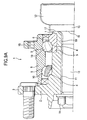
- Figs. 9A and 10 show an example of the wheel-supporting hub unit for supporting the wheels of the car (rear wheels of a car, front wheels of a car, all wheels of a 4WD car) on the suspension of the car, which is disclosed in Japanese Patent Unexamined Publication JP-11 005 404 A (& EP 854 303 A, disclosing all features of the pre-characterizing portions of claims 1 and 3).
- a flange 3 In an outside end portion of an outer peripheral surface of a hub 2 forming the present wheel-supporting hub unit, there is disposed a flange 3.
- a term “outer” side means a side of the hub 2 that is near to outside the car in the width direction of the car in a state where the hub 2 is assembled to the car.
- the term “outer” side means the left side.
- the side of the hub 2 that is near to the center of the car in the width direction of the car is referred to as a "inner” side.
- the "inner” side means the right side.
- an inner raceway 4 which corresponds to a first inner raceway.
- An inner ring 6 includes another inner raceway 4 corresponding to a second inner raceway in its outer peripheral surface.
- FIG. 9B in the inside end portion of the outer peripheral surface of the hub 2, there is formed a small-diameter stepped portion 5.
- An inner ring 6 includes inner raceway 4 corresponding to a first inner raceway and a second inner raceway in its outer peripheral surface.
- the inner ring 6 is fitted with the outer surface of the small-diameter stepped portion 5, and the inside end face of the inner ring 6 is held by a caulking portion 7 formed in the inside end portion of the hub 2.
- the inner ring 6 is held by and between the caulking portion 7 and a stepped surface of the small-diameter stepped portion 5, thereby the inner ring 6 is fixed to the hub 2.
- an outer ring 8 On the periphery of the hub 2, there is disposed an outer ring 8 in such a manner that it is concentric with the hub 2.
- an outer raceways 9, 9 In the inner peripheral surface of the outer ring 8, there are formed a pair of outer raceways 9, 9 corresponding to the first and second outer raceways.
- rolling elements 10, 10 Between the outer raceways 9, 9 and the inner raceways 4, 4, there are disposed rolling elements 10, 10 respectively two or more in number.
- the respective rolling elements 10, 10 there are used balls, however, in the case of a wheel-supporting hub unit for a car which is large in weight, taper rollers may also be used as the rolling elements.
- the hub 2 is formed in a cylindrical shape.
- a female spline portion 11 On the female spline portion 11, there is disposed a constant-velocity joint 12.
- a drive shaft 13 includes a male spline portion formed in its outer peripheral surface and is inserted into the constant-velocity joint 12.
- a nut 14 is threadedly engaged with the leading end portion of the drive shaft 13.
- a stepped portion 15 is formed in the base end portion of the drive shaft 13. The inside end face of the nut 14 is contacted with the outside end face of the hub 2.
- the stepped surface 16 of the stepped portion 15 is contacted with the inside end face of the caulking portion 7 formed in the inside end portion of the hub 2.
- a flat portion 17 is formed to secure a contact area of the caulking portion 7 with respect to the stepped surface 16. The flat portion prevents the contact area from being deformed elastically and collapsing through plastic deformation.
- an outwardly-facing flange-shaped mounting portion 18 In the outer peripheral surface of the outer ring 8, there is formed an outwardly-facing flange-shaped mounting portion 18.
- the outer ring 8 is fixed to a suspension through the outwardly-facing flange-shaped mounting portion 18, and the wheels of the car is fixed to the flange 3.
- the wheels can be rotatably supported on the suspension.
- a rotation transmission shaft (not shown) with its base end portion connected to a differential gear (not shown)
- the hub 2 and the wheels fixed to the hub 2 can be driven or rotated.
- a cylindrical portion 19 formed in the inside end portion of the hub 2 is strongly pressed by a pressing mold. Then, the cylindrical portion 19 is plastic deformed outwardly in the diameter direction thereof. In this case, to the cylindrical portion 19, there are applied not only a force going outwardly in the diameter direction but also a large force going outwardly in the axial direction. Further, in the final stage of such working or plastic deforming operation, a force that goes inwardly in the diameter direction is also applied to the cylindrical portion 19.
- the fitted portion between the inner peripheral surface of the inner ring 6 and the outer peripheral surface of the cylindrical portion 19 can provide a clearance-fit in a part.
- the present invention aims at eliminating the above-mentioned drawbacks found in the conventional method for manufacturing a wheel-supporting hub unit and the conventional pressing mold for manufacturing such a hub unit. Accordingly, it is an object of the invention to provide a method for manufacturing a wheel-supporting hub unit and a pressing mold for manufacturing such a hub unit, which can prevent the diameter of a cylindrical portion formed in the inside end portion of a hub from being reduced in the working operation for forming a caulking portion.
- the present invention there is provided method for manufacturing wheel-supporting hub unit and pressing mold for manufacturing same hub unit.
- the method according to the first aspect of the invention for example, similarly to the previously described conventional wheel-supporting hub unit shown in Figs. 9A, 9B and 10, comprises a hub, a first inner raceway, a stepped portion, an inner ring, an outer ring, and a plurality of rolling elements.
- the hub includes a flange for supporting and fixing wheels in the outer peripheral surface of its outside end portion.
- the first inner raceway is formed in the outer peripheral surface of the middle portion of the hub directly or through the inner ring disposed separately from the hub.
- the stepped portion is formed in the inside end portion of the hub and has a smaller outside diameter dimension than that of the portion where the first inner raceway is formed.
- the inner ring includes a second inner raceway formed in its outer peripheral surface and is fitted with the stepped portion.
- the outer ring includes, in its inner peripheral surface, a first outer raceway opposed to the first inner raceway and a second outer raceway opposed to the second inner raceway, while the outer ring is not rotatable even when it is in use.
- rolling elements are interposed between the first inner raceway and first outer raceway as well as between the second inner raceway and second outer raceway, respectively in two or more in number.
- the inner ring fitted with the stepped portion is connected and fixed to said hub in such a manner that it is held toward a stepped surface of the stepped portion by a caulking portion.
- the caulking portion is formed by plastic deforming which caulks and spreads a cylindrical portion outwardly in the diameter direction of the hub.
- the cylindrical portion is formed in the inside end portion of the hub in such a manner that the inside end portion of the cylindrical portion is projected inwardly from the inner ring fitted with the outer surface of the stepped portion.
- a pressing mold for plastic deforming caulks and spreads a cylindrical portion outwardly in the diameter direction there is used a pressing mold including a cylindrical projecting portion which can be freely pushed into the cylindrical portion. Therefore, a part of the cylindrical portion is superimposed on the inner peripheral surface of the inner ring in the diameter direction. In addition, the part is supported by the cylindrical projecting portion to prevent the cylindrical portion from shifting toward the inside diameter side. That is, the caulking portion is formed in this manner.
- the pressing mold for manufacturing the wheel-supporting hub unit according to the second aspect of the invention is used when enforcing a wheel-supporting hub unit manufacturing method according to the first aspect of the invention. That is, the present pressing mold can be butted against the leading end face of the above-mentioned cylindrical portion to thereby apply to the cylindrical portion not only a force moving in the axial direction but also a force moving outwardly in the diameter direction.
- the pressing mold for manufacturing a wheel-supporting hub unit includes a cylindrical projecting portion slidable into the inside of the cylindrical portion formed in the central portion of the leading end face thereof, and an annular-shaped recessed portion formed in the periphery of the cylindrical projecting portion so as to enclose the entire periphery of the cylindrical projecting portion.
- the outer peripheral surface of the cylindrical projecting portion can be contacted with the inner peripheral surface of the cylindrical portion in such a manner that the annular-shaped recessed portion is butted against the inside end portion of the cylindrical portion to thereby plastic deform the cylindrical portion.
- the operation to plastic deform (caulk and spread) the cylindrical portion outwardly in the diameter direction to form the caulking portion by the present manufacturing pressing mold may be carried out by oscillating and caulking the cylindrical portion.
- an annular-shaped recessed portion which has the following section shape.
- said annular-shaped recessed portion further comprised a bottom surface portion disposed in the periphery of its deepest portion, an inside-diameter-side curved surface portion having a concave-arc-shaped section which continues smoothly with an outer peripheral part of said bottom surface portion or intersects said bottom surface portion at an outer part thereof, a conical-concave-shaped inclined surface portion having a linear-shaped section which continues smoothly with an outer peripheral part of said inside-diameter-side curved surface portion or intersects said inside-diameter-side curved surface portion at an outer part thereof and an outside-diameter-side projecting surface portion having a convex-arc-shaped section which continues smoothly with an outer peripheral part of said inclined surface portion or intersects said inclined surface portion at an outer part thereof.
- These three surface portions may be concentric with one another. Also, as assuming that there is a virtual straight line connecting the oscillation center of the pressing mold with the boundary position between the inside-diameter-side curved surface portion and the inclined surface portion, an angle formed between the inclined surface portion and a perpendicular line with respect to the virtual straight line is defined as a tangent angle. Further, an intersection angle between the present virtual straight line and a virtual plane portion extending at right angles to the oscillation center axis of the pressing mold is defined as an offset angle. Under these conditions, the tangent angle is regulated to the range from 13° to (an angle defined by subtracting said offset angle from 90°).
- the operation to support wheels on a suspension rotatably which is carried out by a wheel-supporting hub unit manufactured by the above-structured wheel-supporting hub unit manufacturing method according to the invention, is similar to the operation of the conventional wheel-supporting hub unit shown in Figs. 9A, 9B and 10.
- the caulking portion is formed by an oscillating and caulking operation while holding the inner peripheral surface of the cylindrical portion by the outer peripheral surface of the cylindrical projecting portion, the cylindrical portion can be prevented from shifting in part inwardly in the diameter direction and the shape of the caulking portion can be regulated strictly as desired. Therefore, there is eliminated a fear that the support strength of the inner ring by the caulking portion can be short. And, in the case of a wheel-supporting hub unit for drive wheels, there is no possibility that the operation to insert the drive shaft into the inside diameter side of the hub can be troublesome.
- the fitted portion between the outer peripheral surface of the cylindrical portion and the inner peripheral surface of the inner ring can be maintained in a close fit state, thereby being able to prevent the occurrence of a creep phenomenon in which the inner ring can rotate with respect to the cylindrical portion.
- the tangent angle of the inclined surface portion formed in the annular-shaped recessed portion of the pressing mold is regulated to the range from 13° to (an angle defined by subtracting said offset angle from 90°), not only the occurrence of burrs in the outer peripheral edge portion of the caulking portion but also the occurrence of cracks in the caulking portion can be prevented, which makes it possible to provide a caulking portion of better quality.
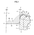
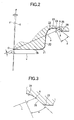
- Figs. 1 to 3 show a first embodiment of a method for manufacturing a wheel-supporting hub unit according to the invention.
- the present invention is characterized not only by an improved method of stably forming a caulking portion 7a for holding an inner ring 6 with respect to a hub 2 but also by an improved pressing mold 20 to be used for enforcing the present method.
- the structures and operations of the other remaining portions of the invention are similar to the conventional wheel-supporting hub unit shown in Figs. 9A, 9B and 10. Therefore, the duplicate illustration and description thereof are omitted or simplified and thus description will be given below mainly of the characteristic portions thereof.
- the inside end portion of a cylindrical portion 19 is formed in the inside end portion of the hub 2.
- the inside end portion projects from the inside end face of the inner ring 6 fitted with the outer surface of a stepped portion 15.
- the stepped portion 15 includes the outer peripheral surface of the cylindrical portion 19.
- the inside end portion is caulked and spread by using the pressing mold 20 assembled to an oscillatory pressing apparatus (not shown), thereby forming the caulking portion 7a.
- the pressing mold 20 is structured such that, in the periphery of a cylindrical projecting portion 21 to be pushed into the cylindrical portion 19, there is formed an annular-shaped recessed portion 22 for forming the caulking portion 7a.
- the shapes and dimensions of the cylindrical projecting portion 21 and annular-shaped recessed portion 22 are regulated in the following manner.
- a linear portion S forms the outer peripheral surface of the cylindrical projecting portion 21 and has a linear-shaped section.
- the linear portion S is also formed in a cylindrical shape having an outside diameter constant in the axial direction thereof, or, in a taper shape tapering slightly toward its leading end (in Figs. 1 to 3, the lower end) in a direction where its outside diameter decreases.
- the outside diameter dimension of the cylindrical projecting portion 21 it is regulated such that, while the pressing mold 20 is oscillatingly shifted.
- the cylindrical portion 19 is plastic deformed to thereby form the caulking portion 7a.
- the cylindrical projecting portion 21 can be moved into the inside diameter side of the cylindrical portion 19 or the caulking portion 7a.
- the cylindrical projecting portion 21 can be contacted with the portion of the inner peripheral surface of the cylindrical portion 19 or the caulking portion 7a, whose phase in the circumferential direction corresponds to (coincides with) the phase of the portion held by the annular-shaped recessed portion 22.
- the inclination angle of the outer peripheral surface of the cylindrical projecting portion 21 with respect to the center axis X of the pressing mold 20 including the cylindrical projecting portion 21 is regulated that the pressing mold 20 is inclined by a set oscillation angle ⁇ (for example, 2°).
- the inclination angle ⁇ ' of the linear portion S with respect to the center axis x of the hub 2 provides a value equal to or slightly larger than the angle ⁇ by which the pressing mold 20 is oscillated and shifted. Specifically, 2° (in case where the outside diameter of the linear portion S is constant) or slightly larger than 2° (in case where the linear portion S has a taper shape).
- the cylindrical projecting portion 21 can be prevented from biting into and interfering with the deformed portion of the inner peripheral surface of the cylindrical portion 19 that has been deformed toward the inside diameter side due to the plastic deformation.
- annular-shaped recessed portion 22 which has the following section shape.
- the section of the deepest portion, namely, the bottom surface portion 23 of the annular-shaped recessed portion 22 is formed to have a smooth concave-arc shape in order that the inside end face (in Fig. 1, the upper end face) of the caulking portion 7a can have a desired shape.
- an inside-diameter-side curved surface portion 24, an inclined surface portion 25 and an outside-diameter-side curved surface portion 26 are respectively arranged from the inside diameter side to the outside diameter side and are concentric with one another.
- the inside-diameter-side curved surface portion 24 is formed such that it smoothly continues with the outer peripheral part of the bottom surface portion 23 and has a concave-arc-shaped section shape.
- the inclined surface portion 25 is formed such that it smoothly continues with the outer peripheral part of the inside-diameter-side curved surface portion 24 and has a linear and conical-concave surface shape.
- the outside-diameter-side curved surface portion 26 is formed such that it smoothly continues with the outer peripheral part of the inclined surface portion 25 and has a convex-arc-shaped section.
- the continuous portions of the bottom surface portion 23, inside-diameter-side curved surface portion 24, inclined surface portion 25 and outside-diameter-side curved surface portion 26 are all formed to be smooth. However, these continuous portions may not be always smooth but they may continue in an intersecting manner (in an un-smoothed manner).
- a virtual straight line u connecting the oscillation center O of the pressing mold 20 with a boundary position A is defined between the inside-diameter-side curved surface portion 24 and inclined surface portion 25.
- An angle ⁇ formed by the inclined surface portion 25 and a straight line perpendicular to the virtual straight line u is defined as a tangent angle.
- an intersection angle ⁇ between the virtual straight line u and a virtual plane v perpendicular to the oscillation center axis x of the pressing mold 20 coincident with the center of the hub 2 is defined as an offset angle.
- the tangent angle ⁇ is regulated to the range from 13° to (an angle defined by subtracting said offset angle ⁇ from 90°).
- the pressing mold 20 is used for forming the caulking portion 7a.
- the pressing mold 20 includes the above-formed cylindrical projecting portion 21 and annular-shaped recessed portion 22.
- the hub 2 may be supported on the support base of an oscillating/caulking apparatus.
- the pressing mold 20 may be supported on the ram of the oscillating/caulking apparatus.
- the pressing mold 20 may be pressed against the cylindrical portion 19 while it is being oscillated and shifted about the oscillation center axis x. As a result of such pressing operation, the cylindrical portion 19 is plastic deformed to thereby provide the caulking portion 7a.
- the cylindrical portion 19 is plastic deformed due to the pressing of the pressing mold 20 against the cylindrical portion 19. Then, the inside-diameter-side curved surface portion 24 and inclined surface portion 25 respectively is formed by the annular-shaped recessed portion 22 of the pressing mold 20. the inside-diameter-side curved surface portion 24 and inclined surface portion 25 respectively are butted against the cylindrical portion 19 to thereby work the leading end portion of the cylindrical portion 19 into the caulking portion 7a. And, in case where the caulking portion 7a is further deformed plastically by the pressing mold 20, a force moving inwardly in the diameter direction is applied to the caulking portion 7a from the inside-diameter-side curved surface portion 24 and inclined surface portion 25.
- the cylindrical portion 19 is going to shift (bulge out) toward the inside diameter side.
- the shifting of the cylindrical portion 19 toward the inside diameter side cannot be prevented. Therefore, not only the close contact between the outer peripheral surface of the stepped portion 15 and the inner peripheral surface of the inner ring 6 can be degraded, but also the inside diameter of the cylindrical portion 19 can be reduced excessively.
- the cylindrical projecting portion 21 is formed in the pressing mold 20, the cylindrical portion 19 can be prevented from shifting toward the inside diameter side.
- the close contact between the outer peripheral surface of the stepped portion 15 and the inner peripheral surface of the inner ring 6 can not only enhance, but also can prevent the inside diameter of the cylindrical portion 19 from being reduced excessively.
- the oscillating/caulking operation is executed while the inner peripheral surface of the cylindrical portion 19 is being held by the outer peripheral surface of the cylindrical projecting portion 21. Therefore, the inner peripheral surface of the cylindrical portion 19 or the caulking portion 7a can be prevented from bulging out inwardly in the diameter direction. As a result of this, the shapes and dimensions of the formed caulking portion 7a and cylindrical portion 19 can be regulated strictly as desired. Therefore, it is eliminated not only a fear that the support strength of the inner ring 6 can be short by the caulking portion 7a, but also a fear that the operation to insert the drive shaft 13 (Figs.
- the tangent angle ⁇ of the inclined surface 25 formed in the annular-shaped recessed portion 22 of the pressing mold 20 is regulated to the range from 13° to (an angle defined by subtracting said offset angle ⁇ from 90°) (for example 20.9°). Therefore, not only the occurrence of burrs in the outer peripheral edge portion of the caulking portion 7a but also the occurrence of cracks in the caulking portion 7a can be prevented. In addition, it is being able to provide a caulking portion 7a of better quality.
- the oscillation center O is situated in the central portion of the leading end face of the cylindrical projecting portion 21 and the offset angle ⁇ is set at an angle of 25°.
- the position of the oscillation center O can be set arbitrarily, provided that it is present on the center axis of the pressing mold 20 or on the extension thereof. In the present embodiment, from the viewpoint of prevention of interference between the components of the oscillating/caulking apparatus as well as from the viewpoint of prevention of interference between the cylindrical projecting portion 21 and cylindrical portion 19.
- the oscillation center O is set at the above position.
- the inventors have confirmed experimentally that, in the case where the tangent angle ⁇ is set at an angle of 13° or more, burrs can be prevented from occurring in the outer peripheral edge portion of the caulking portion 7a. That is, the tangent angle ⁇ was varied in seven ways, namely, 3° , 5° , 10° , 11° , 13° , 20° and 27°. In these seven angles, the caulking portion 7a was visually observed for the thus obtained characteristics thereof. As a result of this, in the case of the four cases having the tangent angle ⁇ of 3° , 5° , 10° , 11° , thread-like burrs occurred in the outer peripheral edge portion of the formed caulking portion 7a. On the other hand, in the case of the remaining three cases having the tangent angle ⁇ of 13° , 20° and 27°, the occurrence of burrs could not be observed in the outer peripheral edge portion of the formed caulking portion 7a.
- the tangent angle ⁇ may be regulated to the range from 13° to (an angle defined by subtracting said offset angle ⁇ from 90°), more preferably, to the range from 20° to 30°.
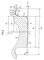
- Figs. 4 and 5 show an example of a dimension range when the invention is applied to a wheel-supporting hub unit for the drive wheels of an ordinary car.
- a portion forming a female spline portion 11 has a thickness T 11 of 5 - 8 mm
- the base half section of the cylindrical portion 19 has a thickness T 19 of 3 - 6 mm
- the inside diameter (the diameter of the inner peripheral surface) of this base half section is 25.2 - 41.8 mm
- an axial distance L 19 from the base end edge of the cylindrical portion 19 to the inside end face of the inner ring 6 is set approximately in the range of 3 - 15 mm.
- the outer peripheral surface of the cylindrical projecting portion 21 of a pressing mold 20 (which will be discussed later) is contacted with the inner peripheral surface of the cylindrical portion 19 in any portion, which is present in the axial distance L 19 . Therefore, it is prevented the cylindrical portion 19 from shifting toward the inside diameter side.
- an angle (oscillation angle) ⁇ formed between the center axis X and oscillation center axis x of the pressing mold 20 is set at 2°.
- the leading end face of the cylindrical projecting portion 21 formed in the leading end face central portion of the pressing mold 20 is formed as a slightly inclined conically-convex surface.
- An intersection angle ⁇ 28 between the bus of the leading end face 28 and a virtual plane intersecting with the center axis X of the pressing mold 20 at right angles is set at 2°.
- an intersection angle ⁇ 29 between the outer peripheral surface 29 of the cylindrical projecting portion 21 and the center axis X of the pressing mold 20 is set in the range of 0 - 2°. Therefore, an intersection angle ⁇ 29 ' between this outer peripheral surface 29 and the above-mentioned oscillation center axis x is, in the largest portion thereof, in the range of 2 - 4°.
- the outside diameter D 21 of the cylindrical projecting portion 21 is set in the range of 25 - 40 mm
- the outside diameter D 22 of an annular-shaped recessed portion 22 existing in the periphery of the cylindrical projecting portion 21 is set in the range of 40 - 60 mm
- the curvature of radius R 24 of the section shape of an inside diameter side curved surface portion 24 formed in the annular-shaped recessed portion 22 is set in the range of 2 - 8 mm
- the curvature of radius R 26 of the section shape of an inside diameter side curved surface portion 26 formed in the annular-shaped recessed portion 22 is set in the range of 0.5 - 5 mm.
- the cylindrical projecting portion 21 of the pressing mold 20 is formed in such a shape as shown in Fig. 5 and has the above-mentioned dimensions.
- the cylindrical projecting portion 21 is inserted into the cylindrical portion 19 of the hub 2 formed in such a shape as shown in Fig. 4 and having the above-mentioned dimensions. Therefore, the cylindrical portion 19 is plastically deformed in the early stage of the deforming operation. In addition, there exists a slight clearance between the inner peripheral surface of the cylindrical portion 19 and the outer peripheral surface of the cylindrical projecting portion 21.
- Fig. 6 shows an example of a hub 2a for forming such hub unit for coupled driving wheels, which belongs to a second embodiment of the invention.
- a circular-shaped recessed hole 30 is formed in the central portion of the inside end face (in Fig. 6, the upper end face) of the hub 2a.
- the diameter of a cylindrical portion 19a in the inside end portion of the hub 2a is, in most cases, slightly smaller than that of the cylindrical portion 19 (Figs. 1, 4) formed in the inside end portion of the hub 2 constituting the previously-described hub unit for drive wheels. Therefore, the diameter of a pressing mold for caulking the inside end portion of the cylindrical portion 19a is also reduced down accordingly.
- the inside end portion of the hub 2a is a solid body and forms the hub unit for coupled driving wheels.
- the axial dimension of the cylindrical portion 19a is formed in the inside end portion of the hub 2a.
- the axial dimension of the cylindrical portion 19a is shorter than the axial dimension of the cylindrical portion 19 (Fig. 4) formed in the inside end portion of the hub 2 which is hollow and forms the hub unit for drive wheels.
- the cylindrical portion 19a having a short axial dimension the range where the outside diameter thereof is reduced due to the deforming operation for forming the caulking portion is limited. Therefore, when compared with the hub unit for drive wheels, a creep phenomenon is not easy to occur. In case where the invention is applied to the hub unit for coupled driving wheels, there can also be obtained an effect to a certain extent.
- hubs forming hub units for coupled driving wheels there is available a hub which is formed of a hollow cylindrical-shaped body for the purpose of reduction in the weight thereof.
- a hub which is formed of a hollow cylindrical-shaped body for the purpose of reduction in the weight thereof.
- the axial dimension of the cylindrical portion thereof is long. In this case, even in the hub for coupled driving wheels, application of the invention can provide a great effect.
- Figs. 7 and 8 respectively show a third embodiment of a method for manufacturing a wheel-supporting hub unit according to the present invention.
- the inside end portion of the cylindrical portion 19 is oscillated and caulked using a pressing mold 20a.
- the inside end portion of the cylindrical portion 19 is thus plastic deformed to thereby form a caulking portion 7b.
- the inside end face of the caulking portion 7b there is formed a flat portion 17.
- the bottom surface portion 23 of an annular-shaped recessed portion 22a is formed in the leading end face of the pressing mold 20a that encloses the cylindrical projecting portion 21.
- the bottom surface portion 23 is formed as a plane portion 31 having a linear section shape.
- this plane portion 31 is formed so as to extend in a direction perpendicular to the center axis x of the hub 2.
- the area of the plane portion 31 (the width dimension of the plane portion 31 in the diameter direction thereof) is set equal or larger than the area of the flat portion 17.
- the plane portion 31 is slightly inclined to the oscillation/shift angle in such a manner that the pressing portion thereof forms right angles with respect to the center axis x of the hub 2. Therefore, to speak strictly, the plane portion 31 is a small conical-shaped convex surface. In the present specification, such portion is also referred to as a plane portion.
- the pressing mold 20a including the plane portion 31 as the bottom surface portion 23 of the annular-shaped recessed portions 22a due to use of the pressing mold 20a including the plane portion 31 as the bottom surface portion 23 of the annular-shaped recessed portions 22a.
- the shape of the plane portion 31 is transferred to the inside end portion of the caulking portion 7b, so that the flat portion 17 is formed in the inside end face of the caulking portion 7b.
- the flat portion 17 is formed in the caulking portion 7b simultaneously when the cylindrical portion 19 is caulked and spread to thereby form the caulking portion 7b. Therefore, the operation to work the caulking portion 7b including the flat portion 17 is easy, which makes it possible to reduce the manufacturing cost of the present hub unit.
- the structures and operations of the remaining portions of the present embodiment are similar to those of the previously described first embodiment and, therefore, equivalent parts are given the same designations and thus the duplicate description thereof is omitted here.
- a method for manufacturing a wheel-supporting hub unit and a pressing mold for manufacturing such hub unit are structured and operate in the above-mentioned manner, there can be provided a wheel-supporting hub unit which not only can fix an inner ring to a hub positively but also, even in case where it is used for a long period of time, can prevent the occurrence of not only a creep phenomenon but also a rickety motion caused by such creep phenomenon.
Landscapes
- Engineering & Computer Science (AREA)
- Mechanical Engineering (AREA)
- General Engineering & Computer Science (AREA)
- Rolling Contact Bearings (AREA)
- Forging (AREA)
- Mounting Of Bearings Or Others (AREA)
Applications Claiming Priority (4)
| Application Number | Priority Date | Filing Date | Title |
|---|---|---|---|
| JP2000362803 | 2000-11-29 | ||
| JP2000362803 | 2000-11-29 | ||
| JP2001268323A JP2002225503A (ja) | 2000-11-29 | 2001-09-05 | 車輪支持用ハブユニットの製造方法とその製造用押型 |
| JP2001268323 | 2001-09-05 |
Publications (3)
| Publication Number | Publication Date |
|---|---|
| EP1211101A2 EP1211101A2 (en) | 2002-06-05 |
| EP1211101A3 EP1211101A3 (en) | 2003-12-10 |
| EP1211101B1 true EP1211101B1 (en) | 2005-04-27 |
Family
ID=26604811
Family Applications (1)
| Application Number | Title | Priority Date | Filing Date |
|---|---|---|---|
| EP01127855A Revoked EP1211101B1 (en) | 2000-11-29 | 2001-11-22 | Method for manufacturing wheel-supporting hub unit and pressing mold for manufacturing same hub unit |
Country Status (4)
| Country | Link |
|---|---|
| US (1) | US6782622B2 (enExample) |
| EP (1) | EP1211101B1 (enExample) |
| JP (1) | JP2002225503A (enExample) |
| DE (1) | DE60110350T2 (enExample) |
Families Citing this family (10)
| Publication number | Priority date | Publication date | Assignee | Title |
|---|---|---|---|---|
| JP4299957B2 (ja) * | 2000-07-17 | 2009-07-22 | 株式会社ジェイテクト | 軸受装置の製造方法 |
| US6485187B1 (en) * | 2000-10-24 | 2002-11-26 | Delphi Technologies, Inc. | Self-retained wheel bearing assembly |
| DE102005018127A1 (de) * | 2005-04-20 | 2006-10-26 | Schaeffler Kg | Stirnverzahnung an einem Kupplungselement zum Übertragen von Drehmomenten |
| JP3923986B2 (ja) * | 2005-05-10 | 2007-06-06 | Ntn株式会社 | 車輪用軸受装置 |
| JP4807773B2 (ja) * | 2005-09-29 | 2011-11-02 | Ntn株式会社 | 駆動車輪用軸受装置 |
| JP5261023B2 (ja) * | 2008-05-13 | 2013-08-14 | Ntn株式会社 | 車輪用軸受装置の加工方法 |
| JP5249147B2 (ja) * | 2009-07-07 | 2013-07-31 | 本田技研工業株式会社 | カール部の成形方法 |
| ITTO20110702A1 (it) * | 2011-07-29 | 2013-01-30 | Skf Ab | Metodo per la formatura di una dentatura frontale su un anello interno di un mozzo ruota |
| CN113631294B (zh) * | 2019-04-10 | 2025-01-03 | 日本精工株式会社 | 铆接装配件的制造方法、轮毂单元轴承的制造方法、铆接装置、铆接装配件、以及车辆的制造方法 |
| EP3892397B1 (en) | 2019-04-10 | 2025-07-30 | NSK Ltd. | Method for manufacturing hub unit bearing, and method for manufacturing vehicle |
Family Cites Families (24)
| Publication number | Priority date | Publication date | Assignee | Title |
|---|---|---|---|---|
| DE4339847C2 (de) * | 1993-11-23 | 2000-09-14 | Kugelfischer G Schaefer & Co | Lagereinheit |
| DE19613441B4 (de) * | 1996-04-04 | 2005-03-24 | Fag Kugelfischer Ag | Verfahren zur Herstellung einer aus mehreren Einzelteilen bestehenden Wälzlagerbaueinheit |
| US5822859A (en) * | 1996-10-07 | 1998-10-20 | General Motors Corporation | Bearing with integrally retained separable race |
| WO1998025772A1 (en) * | 1996-12-10 | 1998-06-18 | Kelsey Hayes Company | Vehicle wheel hub and bearing retention system and method for producing same |
| IT1289780B1 (it) * | 1996-12-20 | 1998-10-16 | Skf Ind Spa | Gruppo mozzo-giunto omocinetico per una ruota motrice,particolarmente per un autoveicolo. |
| US5822860A (en) * | 1996-12-23 | 1998-10-20 | General Motors Corporation | Integrally retained bearing race with improved twisting resistance |
| JP3533883B2 (ja) | 1997-06-16 | 2004-05-31 | 日本精工株式会社 | 車輪支持用ハブユニット |
| EP0854303B1 (en) * | 1997-01-17 | 2003-10-29 | Nsk Ltd | Rolling bearing unit for supporting vehicle wheel |
| JP3845942B2 (ja) * | 1997-03-31 | 2006-11-15 | 日本精工株式会社 | 車輪支持用ハブユニット |
| GB9713343D0 (en) * | 1997-06-24 | 1997-08-27 | Timken Co | Process and machine for uniting rotatable machine components |
| US6105251A (en) * | 1997-10-20 | 2000-08-22 | General Motors Corporation | Integrally retained bearing race with improved twisting resistance |
| US6640438B2 (en) * | 1998-06-22 | 2003-11-04 | The Timken Company | Process and machine for uniting rotatable machine components |
| JP2000038005A (ja) | 1998-07-22 | 2000-02-08 | Koyo Seiko Co Ltd | 車両用ハブユニットのかしめ方法 |
| JP4326046B2 (ja) * | 1998-09-09 | 2009-09-02 | 株式会社ジェイテクト | 車両用軸受装置および車両用軸受装置の製造方法 |
| DE69932782T2 (de) * | 1998-09-11 | 2007-12-27 | Jtekt Corp., Osaka | Lagervorrichtung |
| JP4016499B2 (ja) * | 1998-09-11 | 2007-12-05 | 株式会社ジェイテクト | ハブユニットの製造方法 |
| JP4178204B2 (ja) * | 1999-05-11 | 2008-11-12 | 株式会社ジェイテクト | 軸受装置の製造方法 |
| JP4123643B2 (ja) * | 1999-06-21 | 2008-07-23 | 株式会社ジェイテクト | 軸力管理方法 |
| DE60020754T2 (de) * | 1999-12-20 | 2005-11-03 | Nsk Ltd. | Verfahren zu ihrer Herstellung einer wälzgelagerten Radlagereinheit |
| JP2001268323A (ja) | 2000-03-22 | 2001-09-28 | Nikon Corp | 画像入力装置 |
| US6485187B1 (en) * | 2000-10-24 | 2002-11-26 | Delphi Technologies, Inc. | Self-retained wheel bearing assembly |
| US6622377B1 (en) * | 2000-10-24 | 2003-09-23 | Delphi Technologies, Inc. | Wheel bearing with separable inner race processing feature |
| US6772615B2 (en) * | 2001-09-20 | 2004-08-10 | Nsk Ltd. | Method of manufacturing hub unit for supporting wheel and die for manufacturing the same |
| US6532666B1 (en) * | 2001-11-29 | 2003-03-18 | The Timken Company | Process for capturing a bearing race on a spindle |
-
2001
- 2001-09-05 JP JP2001268323A patent/JP2002225503A/ja active Pending
- 2001-11-22 EP EP01127855A patent/EP1211101B1/en not_active Revoked
- 2001-11-22 DE DE60110350T patent/DE60110350T2/de not_active Expired - Fee Related
- 2001-11-26 US US09/991,901 patent/US6782622B2/en not_active Expired - Lifetime
Also Published As
| Publication number | Publication date |
|---|---|
| US20020062564A1 (en) | 2002-05-30 |
| EP1211101A2 (en) | 2002-06-05 |
| DE60110350T2 (de) | 2005-10-06 |
| JP2002225503A (ja) | 2002-08-14 |
| EP1211101A3 (en) | 2003-12-10 |
| US6782622B2 (en) | 2004-08-31 |
| DE60110350D1 (de) | 2005-06-02 |
Similar Documents
| Publication | Publication Date | Title |
|---|---|---|
| US7104893B2 (en) | Wheel drive unit | |
| EP1177918B1 (en) | Drive unit for the wheels of a vehicle and its assembly method | |
| EP1270268B1 (en) | Rolling bearing unit for a drive wheel and a wheel driving unit | |
| EP1288021B1 (en) | A bearing apparatus for wheel | |
| EP1125765B1 (en) | Apparatus for driving wheel of automobile | |
| EP1777079B1 (en) | Wheel drive unit | |
| US20070217728A1 (en) | Hub Unit, Rolling Bearing Assembly and Manufacture Method Thereof, as Well as Assembling Apparatus for Rolling Bearing Assebly and Assebly Method Thereof | |
| EP1211101B1 (en) | Method for manufacturing wheel-supporting hub unit and pressing mold for manufacturing same hub unit | |
| EP1286087A1 (en) | Two piece axle shaft | |
| EP1375943B1 (en) | Rolling ball slip joint formed from two tubular members | |
| EP1321312B1 (en) | Bearing apparatus for a driving wheel of vehicle | |
| KR19990063223A (ko) | 두 개의 고정 조인트 및 별도의 슬라이딩 수단을 갖춘 cv 조인트 축 | |
| EP2708376A1 (en) | Vehicle bearing apparatus | |
| JP2000264008A (ja) | 自動車の車輪ハブのベアリング及びその装着方法 | |
| GB2339464A (en) | Constant velocity fixed joint. | |
| EP1857696B1 (en) | Cross joint and vehicular steering system including the same | |
| US6922897B1 (en) | Ball cage | |
| EP1902861B1 (en) | Wheel rolling bearing apparatus | |
| JP2001163003A (ja) | 車輪駆動用軸受ユニット及び車輪駆動用軸受ユニット用結合部材の製造方法 | |
| EP1724035B1 (en) | Method of manufacturing a driveshaft assembly | |
| JP2001158206A (ja) | 車輪駆動用軸受ユニット | |
| AU2002241350A1 (en) | Wheel drive unit |
Legal Events
| Date | Code | Title | Description |
|---|---|---|---|
| PUAI | Public reference made under article 153(3) epc to a published international application that has entered the european phase |
Free format text: ORIGINAL CODE: 0009012 |
|
| 17P | Request for examination filed |
Effective date: 20011122 |
|
| AK | Designated contracting states |
Kind code of ref document: A2 Designated state(s): AT BE CH CY DE DK ES FI FR GB GR IE IT LI LU MC NL PT SE TR |
|
| AX | Request for extension of the european patent |
Free format text: AL;LT;LV;MK;RO;SI |
|
| PUAL | Search report despatched |
Free format text: ORIGINAL CODE: 0009013 |
|
| AK | Designated contracting states |
Kind code of ref document: A3 Designated state(s): AT BE CH CY DE DK ES FI FR GB GR IE IT LI LU MC NL PT SE TR |
|
| AX | Request for extension of the european patent |
Extension state: AL LT LV MK RO SI |
|
| AKX | Designation fees paid |
Designated state(s): DE GB |
|
| GRAP | Despatch of communication of intention to grant a patent |
Free format text: ORIGINAL CODE: EPIDOSNIGR1 |
|
| GRAS | Grant fee paid |
Free format text: ORIGINAL CODE: EPIDOSNIGR3 |
|
| GRAA | (expected) grant |
Free format text: ORIGINAL CODE: 0009210 |
|
| AK | Designated contracting states |
Kind code of ref document: B1 Designated state(s): DE GB |
|
| REG | Reference to a national code |
Ref country code: GB Ref legal event code: FG4D |
|
| REG | Reference to a national code |
Ref country code: IE Ref legal event code: FG4D |
|
| REF | Corresponds to: |
Ref document number: 60110350 Country of ref document: DE Date of ref document: 20050602 Kind code of ref document: P |
|
| PG25 | Lapsed in a contracting state [announced via postgrant information from national office to epo] |
Ref country code: GB Free format text: LAPSE BECAUSE OF NON-PAYMENT OF DUE FEES Effective date: 20051122 |
|
| PLBI | Opposition filed |
Free format text: ORIGINAL CODE: 0009260 |
|
| PLAX | Notice of opposition and request to file observation + time limit sent |
Free format text: ORIGINAL CODE: EPIDOSNOBS2 |
|
| 26 | Opposition filed |
Opponent name: AKTIEBOLAGET SKF Effective date: 20060125 |
|
| PG25 | Lapsed in a contracting state [announced via postgrant information from national office to epo] |
Ref country code: DE Free format text: LAPSE BECAUSE OF NON-PAYMENT OF DUE FEES Effective date: 20060601 |
|
| GBPC | Gb: european patent ceased through non-payment of renewal fee |
Effective date: 20051122 |
|
| RDAF | Communication despatched that patent is revoked |
Free format text: ORIGINAL CODE: EPIDOSNREV1 |
|
| RDAG | Patent revoked |
Free format text: ORIGINAL CODE: 0009271 |
|
| STAA | Information on the status of an ep patent application or granted ep patent |
Free format text: STATUS: PATENT REVOKED |
|
| 27W | Patent revoked |
Effective date: 20061118 |