EP1210506B1 - Fluidkühlvorrichtung - Google Patents
Fluidkühlvorrichtung Download PDFInfo
- Publication number
- EP1210506B1 EP1210506B1 EP00958402A EP00958402A EP1210506B1 EP 1210506 B1 EP1210506 B1 EP 1210506B1 EP 00958402 A EP00958402 A EP 00958402A EP 00958402 A EP00958402 A EP 00958402A EP 1210506 B1 EP1210506 B1 EP 1210506B1
- Authority
- EP
- European Patent Office
- Prior art keywords
- fluid
- cooling means
- filter
- filtering
- cooling
- Prior art date
- Legal status (The legal status is an assumption and is not a legal conclusion. Google has not performed a legal analysis and makes no representation as to the accuracy of the status listed.)
- Expired - Lifetime
Links
- 239000012530 fluid Substances 0.000 title claims abstract description 69
- 238000001816 cooling Methods 0.000 title claims abstract description 56
- 238000001914 filtration Methods 0.000 claims description 10
- 238000005086 pumping Methods 0.000 claims description 6
- 239000002826 coolant Substances 0.000 claims description 3
- XLYOFNOQVPJJNP-UHFFFAOYSA-N water Substances O XLYOFNOQVPJJNP-UHFFFAOYSA-N 0.000 claims description 3
- 238000012544 monitoring process Methods 0.000 claims 1
- 239000010687 lubricating oil Substances 0.000 abstract description 3
- 239000000243 solution Substances 0.000 description 4
- 239000003921 oil Substances 0.000 description 3
- 238000011109 contamination Methods 0.000 description 2
- 238000010586 diagram Methods 0.000 description 2
- 230000000903 blocking effect Effects 0.000 description 1
- 239000000356 contaminant Substances 0.000 description 1
- 230000001419 dependent effect Effects 0.000 description 1
- 230000000694 effects Effects 0.000 description 1
- 239000010720 hydraulic oil Substances 0.000 description 1
- 238000001746 injection moulding Methods 0.000 description 1
- 238000003754 machining Methods 0.000 description 1
- 238000012806 monitoring device Methods 0.000 description 1
- 230000002040 relaxant effect Effects 0.000 description 1
Images


Classifications
-
- F—MECHANICAL ENGINEERING; LIGHTING; HEATING; WEAPONS; BLASTING
- F16—ENGINEERING ELEMENTS AND UNITS; GENERAL MEASURES FOR PRODUCING AND MAINTAINING EFFECTIVE FUNCTIONING OF MACHINES OR INSTALLATIONS; THERMAL INSULATION IN GENERAL
- F16H—GEARING
- F16H57/00—General details of gearing
- F16H57/04—Features relating to lubrication or cooling or heating
- F16H57/0412—Cooling or heating; Control of temperature
- F16H57/0413—Controlled cooling or heating of lubricant; Temperature control therefor
-
- F—MECHANICAL ENGINEERING; LIGHTING; HEATING; WEAPONS; BLASTING
- F01—MACHINES OR ENGINES IN GENERAL; ENGINE PLANTS IN GENERAL; STEAM ENGINES
- F01M—LUBRICATING OF MACHINES OR ENGINES IN GENERAL; LUBRICATING INTERNAL COMBUSTION ENGINES; CRANKCASE VENTILATING
- F01M1/00—Pressure lubrication
- F01M1/10—Lubricating systems characterised by the provision therein of lubricant venting or purifying means, e.g. of filters
-
- F—MECHANICAL ENGINEERING; LIGHTING; HEATING; WEAPONS; BLASTING
- F01—MACHINES OR ENGINES IN GENERAL; ENGINE PLANTS IN GENERAL; STEAM ENGINES
- F01M—LUBRICATING OF MACHINES OR ENGINES IN GENERAL; LUBRICATING INTERNAL COMBUSTION ENGINES; CRANKCASE VENTILATING
- F01M11/00—Component parts, details or accessories, not provided for in, or of interest apart from, groups F01M1/00 - F01M9/00
- F01M11/03—Mounting or connecting of lubricant purifying means relative to the machine or engine; Details of lubricant purifying means
-
- F—MECHANICAL ENGINEERING; LIGHTING; HEATING; WEAPONS; BLASTING
- F16—ENGINEERING ELEMENTS AND UNITS; GENERAL MEASURES FOR PRODUCING AND MAINTAINING EFFECTIVE FUNCTIONING OF MACHINES OR INSTALLATIONS; THERMAL INSULATION IN GENERAL
- F16H—GEARING
- F16H57/00—General details of gearing
- F16H57/04—Features relating to lubrication or cooling or heating
- F16H57/0412—Cooling or heating; Control of temperature
- F16H57/0415—Air cooling or ventilation; Heat exchangers; Thermal insulations
-
- F—MECHANICAL ENGINEERING; LIGHTING; HEATING; WEAPONS; BLASTING
- F01—MACHINES OR ENGINES IN GENERAL; ENGINE PLANTS IN GENERAL; STEAM ENGINES
- F01M—LUBRICATING OF MACHINES OR ENGINES IN GENERAL; LUBRICATING INTERNAL COMBUSTION ENGINES; CRANKCASE VENTILATING
- F01M11/00—Component parts, details or accessories, not provided for in, or of interest apart from, groups F01M1/00 - F01M9/00
- F01M11/03—Mounting or connecting of lubricant purifying means relative to the machine or engine; Details of lubricant purifying means
- F01M2011/031—Mounting or connecting of lubricant purifying means relative to the machine or engine; Details of lubricant purifying means characterised by mounting means
- F01M2011/033—Mounting or connecting of lubricant purifying means relative to the machine or engine; Details of lubricant purifying means characterised by mounting means comprising coolers or heat exchangers
-
- F—MECHANICAL ENGINEERING; LIGHTING; HEATING; WEAPONS; BLASTING
- F01—MACHINES OR ENGINES IN GENERAL; ENGINE PLANTS IN GENERAL; STEAM ENGINES
- F01M—LUBRICATING OF MACHINES OR ENGINES IN GENERAL; LUBRICATING INTERNAL COMBUSTION ENGINES; CRANKCASE VENTILATING
- F01M11/00—Component parts, details or accessories, not provided for in, or of interest apart from, groups F01M1/00 - F01M9/00
- F01M11/03—Mounting or connecting of lubricant purifying means relative to the machine or engine; Details of lubricant purifying means
- F01M2011/031—Mounting or connecting of lubricant purifying means relative to the machine or engine; Details of lubricant purifying means characterised by mounting means
- F01M2011/035—Mounting or connecting of lubricant purifying means relative to the machine or engine; Details of lubricant purifying means characterised by mounting means comprising oil pumps
Definitions
- the invention relates to a fluid cooling device combined in a structural unit cooling, filtering and pumping device, wherein in a fluid circuit funded by the pumping device fluid filterable by the filter device and the cooling device is cooled and wherein the Filterelrides has at least one interchangeable in their pollution filter element.
- the mentioned circulating-cooling filter unit is a compact and easy to install unit for filter cooling circuits, preferably in the bypass.
- To connect the known fluid cooling device is therefore only a hydraulic piping from and to the tank and the power supply to install.
- the connectable in the secondary flow fluid cooling device has as essential components a low-noise pump working, a fluid filter and an oil-water plate heat exchanger.
- Applications of the known units are plastic injection molding machines, presses, machining centers, wind turbines and gearboxes.
- the addressed filter device or the filter of the fluid cooling device is to be changed from time to time depending on its degree of soiling, i. to replace with a new device or filter unit.
- Another possibility is to provide a switching filter that provides a filtered lubricating oil supply even in the case of the filter element change.
- the pertinent switching filter occupies a relatively large amount of space and more expensive overall the known solutions.
- the present invention seeks to further improve the known fluid cooling devices to the effect that the addressed filter element change without additional effort is also possible if the downstream lubricating oil supply is not turned off.
- This object is achieved by a fluid cooling device having the features of claim 1.
- a controllable shut-off is provided with the filter unit of the fluid supply can be separated so that the cooling device is further supplied with the fluid to be cooled, the fluid or oil flow through a kind of bypass led past the filter to be changed and when heated by the cooling device for further use in a working machine or the like. cooled.
- the inventive solution is inexpensive to implement and allows a safe filter element change, without the operator security risks subject. Since the filter element change usually takes place quickly, the imparted via the bypass arrangement contaminants to the fluid cooling are acceptable and affect the subsequent fluid supply for a machine or the like. Not.
- controllable shut-off unit consists of a switching valve, wherein for the fluid supply of the cooling device within the fluid circuit this has a connecting line in the secondary branch, which opens at the end into the supply line for the filter and the cooling device.
- the switching valve is actuated by hand and provided with a latching device which retains the switchable position such predetermined, which ensures the reliability of the device.
- the fluid cooling device comprises in a unit 10 in each case at least one cooling device 12, a filter device 14 and a pump device 16.
- the conveyed in a fluid circuit 18 of the pump means 16 fluid for example in the form of hydraulic oil is filterable by the filter device 14 and the like of the cooling device 12 for later use in a work machine. cooled.
- the hydraulic pump of the pump device 16 is driven by means of an electric motor 20, wherein in bypass to the actual hydraulic pump of the pump device 16 in the direction of the suction port opening, spring-loaded check valve 22 is present.
- the filter device 14 has at least one filter element 24 that is exchangeable when contaminated, wherein an activatable shut-off unit 26 is provided for replacement of the respective filter element 24 in the fluid circuit 18, with which the filter device 14 can be separated from the pump device 16 so that the cooling device 12 continues is supplied with the fluid to be cooled through the fluid circuit 18.
- the controllable shut-off unit 26 preferably consists of a 2/2-way switching valve 28, wherein for the fluid supply of the cooling device 12 within the fluid circuit 18 this in the secondary branch has a connecting line 30, the end in the supply line 32 for the filter device 14 and the cooling device 12th empties.
- the switching valve 28 is operable by a provided with a knurling 34 control part 36 by hand and provided with a locking device 38 which retains the so manually definable switching position.
- first and second check valve 42 and 40 respectively.
- first check valve 40 in the supply line 32 in front of the filter device 14 part of the switching valve 28, which results in particular from the circuit diagram of FIG.
- the first check valve 40 In the non-actuated switching position, as shown in Figure 1, the first check valve 40 is spring-loaded in the direction of its blocking position kept switched into the supply line 32, whereas in the other, not shown switching position, the pertinent supply line 32 is interrupted or shut off.
- the aforementioned check valves 40, 42, 44 are arranged.
- All check valves 40, 42 and 44 are spring-loaded in the direction of their closed position shown in Figure 1, wherein the closing pressure of the check valve 42 in the connecting line 30 of the secondary branch is greater than the closing pressure of at least one of the check valves 40, 44 in the supply line 32nd
- a differential pressure locking device 48 which detects the differential pressure in the fluid direction before and after the filter element 24 and communicates to the plant operator at a predetermined threshold at higher differential pressures and thus relevant pollution in that an element change of the filter element 24 is now present and must be carried out.
- the mentioned differential pressure is seen in the fluid direction of the fluid circuit 18 between shut-off 26 and filter element 24 and between the cooling device 12 and the third check valve 44 at one connection point 46th performed.
- a differential pressure-locking device 48 is preferably a pressure switch use, which switches at a predetermined threshold and then displays the necessary filter element change.
- the cooling device 12 has a plate heat exchanger 50, wherein a fluid, preferably water, in the countercurrent 52 cools the heated fluid as the cooling medium.
- a control unit 54 is provided which, after exceeding an adjustable temperature threshold, the cooling device 12 switches on or falls below the temperature threshold, for example 45 ° C, the unheated fluid, bypassing the cooling device 12 to the tank T via the fluid circuit eighteenth returns.
- the switching valve 28 of the shut-off unit 26 is actuated manually via the actuating part 36 and brought into its closed position.
- the fluid flow from the pumping device 16 is then supplied to the check valve 42 via the connecting line 30 directly to the cooling device 12 for a continuous cooling.
- the check valve 42 thus serves as a filter bypass valve to bypass the filter unit.
- the operating pressure within the fluid circuit 18 automatically closes the check valve 44 in the supply line 32.
- the filter element 24 of the filter device 14 is thus completely separated from the fluid flow of the permanently continuing working circle.
- the filter element 24 which is dirty, against a new unused filter element change.
- the check valve 42 closes automatically by spring force and redirects the flow of oil through the filter element 24 of the filter device 14.
- the third check valve 44 also opens automatically and the addressed fluid circuit 18 operates again in the desired filtration operation.
- the closing force of the check valve 42 is designed to be stronger than the closing force of the check valve 40, to ensure that in the unactuated state of the switching valve 26, the bypass function does not enter unintentionally into force.
Landscapes
- Engineering & Computer Science (AREA)
- General Engineering & Computer Science (AREA)
- Mechanical Engineering (AREA)
- Fluid-Pressure Circuits (AREA)
- Filtration Of Liquid (AREA)
- Devices That Are Associated With Refrigeration Equipment (AREA)
- Ultra Sonic Daignosis Equipment (AREA)
- Crystals, And After-Treatments Of Crystals (AREA)
- Manufacture, Treatment Of Glass Fibers (AREA)
- Details Of Measuring And Other Instruments (AREA)
- Cooling Or The Like Of Semiconductors Or Solid State Devices (AREA)
Description
- Die Erfindung betrifft eine Fluidkühlvorrichtung mit in einer Baueinheit zusammengefaßter Kühl-, Filter- und Pumpeneinrichtung, wobei in einem Fluidkreislauf von der Pumpeneinrichtung gefördertes Fluid von der Filtereinrichtung filterbar und von der Kühleinrichtung kühlbar ist und wobei die Filterelrrichtung mindestens ein bei ihrer Verschmutzung auswechselbares Filterelement aufweist.
- Bei bekannten Lösungen, wie sie frei auf dem Markt erhältlich sind, ist die angesprochene Umpump-Kühl-Filtereinheit eine kompakte und montagefreundliche Einheit für Filterkühlkreisläufe, vorzugsweise im Nebenstrom. Zum Anschließen der bekannten Fluidkühlvorrichtung ist mithin nur eine hydraulische Verrohrung von und zum Tank sowie die Spannungsversorgung zu installieren. Die im Nebenstrom anschließbare Fluidkühlvorrichtung weist als wesentliche Bestandteile eine geräuscharm arbeitende Förderpumpe auf, einen Fluidfilter sowie einen Öl-Wasser-Plattenwärmetauscher. Anwendungsbereiche der bekannten Einheiten sind Kunststoffspritzgußmaschinen, Pressen, Bearbeitungszentren, Windkraftanlagen und Getriebe.
- Die angesprochene Filtereinrichtung bzw. der Filter der Fluidkühlvorrichtung ist in Abhängigkeit seines Verschmutzungsgrades von Zeit zu Zeit zu wechseln, d.h. gegen eine neue Einrichtung bzw. Filtereinheit auszutauschen. Bei den bekannten Lösungen muß hierzu entweder die gesamte Fluidkühlvorrichtung stillgelegt werden mit der Folge, daß die gesamte Fluidanlage, in der die Fluidkühlvorrichtung eingesetzt ist, abgeschaltet werden muß. Eine andere Möglichkeit besteht darin, einen Umschaltfilter vorzusehen, der eine filtrierte Schmierölversorgung auch für den Fall des Filterelementwechsels vorsieht. Der dahingehende Umschaltfilter nimmt jedoch relativ viel Bauraum ein und verteuert insgesamt die bekannten Lösungen.
- Ausgehend von diesem Stand der Technik liegt der Erfindung die Aufgabe zugrunde, die bekannten Fluidkühlvorrichtungen dahingehend weiter zu verbessern, daß der angesprochene Filterelementwechsel ohne zusätzlichen Aufwand auch dann möglich ist, wenn die nachgeordnete Schmierölversorgung nicht abgestellt wird. Eine dahingehende Aufgabe löst eine Fluidkühlvorrichtung mit den Merkmalen des Anspruches 1.
- Dadurch, daß für einen Austausch des jeweiligen Filterelementes im Fluidkreislauf eine ansteuerbare Absperreinheit vorhanden ist, mit der die Filtereinheit von der Fluidversorgung derart abtrennbar ist, daß die Kühleinrichtung weiter mit dem zu kühlenden Fluid versorgt ist, wird der Fluid- oder Ölstrom über einen Art Bypass an dem zu wechselnden Filter vorbeigeleitet und bei Erhitzung von der Kühleinrichtung für die weitere Verwendung bei einer Arbeitsmaschine od.dgl. gekühlt.
- Die erfindungsgemäße Lösung ist kostengünstig realisierbar und erlaubt einen sicheren Filterelementwechsel, ohne daß die Bedienperson Sicherheitsrisiken unterliegt. Da der Filterelementwechsel in der Regel rasch erfolgt, sind die über die Bypass-Anordnung weitergegebenen Verschmutzungen an die Fluidkühlung hinnehmbar und beeinträchtigen die spätere Fluidversorgung für eine Arbeitsmaschine od.dgl. nicht.
- Bei einer bevorzugten Ausführungsform der erfindungsgemäßen Fluidkühlvorrichtung besteht die ansteuerbare Absperreinheit aus einem Schaltventil, wobei für die Fluidversorgung der Kühleinrichtung innerhalb des Fluidkreislaufes diese im Nebenzweig eine Verbindungsleitung aufweist, die endseitig in die Versorgungsleitung für die Filter und die Kühleinrichtung mündet. Hierdurch ist eine besonders kompakt aufbauende Fluidkühlvorrichtung erreicht. Vorzugsweise ist dabei das Schaltventil von Hand betätigbar und mit einer Rasteinrichtung versehen, die die derart vorgebbare Schaltstellung beibehält, was die Funktionssicherheit der Vorrichtung gewährleistet.
- Weitere vorteilhafte Ausführungsformen sind Gegenstand der Unteransprüche.
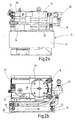
- Im folgenden wird eine Ausführungsform der erfindungsgemäßen Fluidkühlvorrichtung anhand der Zeichnung näher erläutert. Es zeigen in prinzipieller und nicht maßstäblicher Darstellung die
- Fig.1
- eine Schaltdarstellung der Fluidkühlvorrichtung;
- Fig.2a,2b und 2c
- in Vorder-, Seiten- und Draufsicht die Fluidkühlvorrichtung nach der Fig.1.
- Die Fluidkühlvorrichtung weist in einer Baueinheit 10 zusammengefaßt jeweils mindestens eine Kühleinrichtung 12, eine Filtereinrichtung 14 sowie eine Pumpeneinrichtung 16 auf. Das in einem Fluidkreislauf 18 von der Pumpeneinrichtung 16 geförderte Fluid, beispielsweise in Form von Hydrauliköl, ist von der Filtereinrichtung 14 filterbar und von der Kühleinrichtung 12 für die spätere Verwendung bei einer Arbeitsmaschine od.dgl. kühlbar. Die Hydropumpe der Pumpeneinrichtung 16 ist dabei mittels eines Elektromotors 20 antreibbar, wobei im Nebenschluß zu der eigentlichen Hydropumpe der Pumpeneinrichtung 16 ein in Richtung zum Sauganschluß hin öffnendes, federbelastetes Rückschlagventil 22 vorhanden ist.
- Die Filtereinrichtung 14 weist mindestens ein bei ihrer Verschmutzung auswechselbares Filterelement 24 auf, wobei für einen Austausch des jeweiligen Filterelementes 24 im Fluidkreislauf 18 eine ansteuerbare Absperreinheit 26 vorhanden ist, mit der die Filtereinrichtung 14 von der Pumpeneinrichtung 16 derart abtrennbar ist, daß die Kühleinrichtung 12 weiter mit dem zu kühlenden Fluid über den Fluidkreislauf 18 versorgt ist.
- Die ansteuerbare Absperreinheit 26 besteht vorzugsweise aus einem 2/2-Wege-Schaltventil 28, wobei für die Fluidversorgung der Kühleinrichtung 12 innerhalb des Fluidkreislaufes 18 dieser im Nebenzweig eine Verbindungsleitung 30 aufweist, die endseitig in die Versorgungsleitung 32 für die Filtereinrichtung 14 und die Kühleinrichtung 12 mündet. Das Schaltventil 28 ist über ein mit einer Rändelung 34 versehenes Stellteil 36 von Hand betätigbar und mit einer Rasteinrichtung 38 versehen, die die derart von Hand vorgebbare Schaltstellung beibehält.
- In die angesprochene Verbindungsleitung 30 ist, ebenso wie in die Versorgungsleitung 32, ein in Richtung der Kühleinrichtung 12 öffnendes erstes und zweites Rückschlagventil 42 bzw. 40 vorhanden. Dabei ist das eine erste Rückschlagventil 40 in der Versorgungsleitung 32 vor der Filtereinrichtung 14 Teil des Schaltventils 28, was sich insbesondere aus der Schaltdarstellung nach der Fig.1 ergibt. In der nicht betätigten Schaltstellung, wie in Fig.1 dargestellt, ist das erste Rückschlagventil 40 federbelastet in Richtung seiner Sperrstellung gehalten in die Versorgungsleitung 32 geschaltet, wohingegen in der anderen, nicht dargestellten Schaltstellung die dahingehende Versorgungsleitung 32 unterbrochen oder abgesperrt ist. In der Versorgungsleitung 32 wiederum in Richtung des strömenden Fluids vor und hinter der Filtereinrichtung 14 und zwischen den Anschlußstellen 46 der Verbindungsleitung 30 sind die angesprochenen Rückschlagventile 40, 42, 44 angeordnet. Alle Rückschlagventile 40, 42 und 44 sind federbelastet in Richtung ihrer in der Fig.1 dargestellten Schließstellung gehalten, wobei der Schließdruck des Rückschlagventils 42 in der Verbindungsleitung 30 des Nebenzweiges größer ist als der Schließdruck mindestens eines der Rückschlagventile 40, 44 in der Versorgungsleitung 32.
- Um festzustellen, wie der Verschmutzungsgrad des Filterelementes 24 der Filtereinrichtung 14 ist, ist eine Differenzdruck-Feststelleinrichtung 48 vorhanden, die den Differenzdruck in Fluidrichtung vor und hinter dem Filterelement 24 feststellt und bei einem vorgebbaren Schwellenwert bei höheren Differenzdrücken und somit bei relevanter Verschmutzung dem Anlagenbetreiber mitteilt, daß ein Elementwechsel des Filterelementes 24 nunmehr ansteht und vorzunehmen ist. Der angesprochene Differenzdruck wird dabei in Fluidrichtung des Fluidkreislaufes 18 gesehen zwischen Absperreinheit 26 und Filterelement 24 sowie zwischen der Kühleinrichtung 12 und dem dritten Rückschlagventil 44 an der einen Anschlußstelle 46 vorgenommen. Als Differenzdruck-Feststelleinrichtung 48 findet vorzugsweise ein Druckschalter Verwendung, der bei einem vorgebbaren Schwellenwert schaltet und dann den notwendigen Filterelementwechsel anzeigt.
- Die Kühleinrichtung 12 weist insbesondere einen Plattenwärmetauscher 50 auf, wobei als Kühlmedium ein Fluid, vorzugsweise Wasser, im Gegenstrom 52 das erhitzte Fluid kühlt. Die Anschlüsse für den dahingehenden Gegenstrombetrieb mit einem Kühlmedium sind in den Figuren entsprechend dargestellt. Für den Betrieb der Kühleinrichtung 12 ist eine Steuereinheit 54 vorgesehen, die nach Überschreiten eines einstellbaren Temperaturschwellenwertes die Kühleinrichtung 12 zuschaltet oder bei Unterschreiten des Temperaturschwellenwertes, beispielsweise 45°C, das nicht erwärmte Fluid unter Umgehung der Kühleinrichtung 12 an den Tank T über den Fluidkreislauf 18 zurückführt.
- Zeigt die Differenzdruck-Feststelleinrichtung als Überwachungseinrichtung 48 eine Verschmutzung der Filtereinrichtung 14 mit ihrem Filterelement 24 an, wird das Schaltventil 28 der Absperreinheit 26 über das Stellteil 36 von Hand betätigt und in seine abgesperrte Stellung gebracht. Der Fluidstrom von der Pumpeneinrichtung 16 wird dann an dem Rückschlagventil 42 vorbei über die Verbindungsleitung 30 unmittelbar der Kühleinrichtung 12 für eine fortlaufende Kühlung zugeführt. Das Rückschlagventil 42 dient mithin als Filterbypassventil zur Umgehung der Filtereinheit. Der Betriebsdruck innerhalb des Fluidkreislaufes 18 verschließt dabei automatisch das Rückschlagventil 44 in der Versorgungsleitung 32. Das Filterelement 24 der Filtereinrichtung 14 ist mithin vollständig vom Fluidstrom des permanent weiterarbeitenden Kreises getrennt. Durch Entspannen des Inhaltes des Filtergehäuses 56 über die Ablaßschraube 58 (vgl. Fig.2b) kann das Filterelement 24, welches verschmutzt ist, gegen ein neues unbenutztes Filterelement gewechselt werden. Nach erfolgtem Elementwechsel und Verschließen der Ablaßbohrung über die Ablaßschraube 58 kann am Schaltventil 28 der Ölstrom zum Filterelement 24 wiederum freigegeben werden. Das Rückschlagventil 42 schließt dann automatisch durch Federkraft und lenkt den Ölstrom erneut durch das Filterelement 24 der Filtereinrichtung 14. Das dritte Rückschlagventil 44 öffnet ebenfalls automatisch und der angesprochene Fluidkreislauf 18 arbeitet wieder im gewünschten Filtrationsbetrieb. Die Schließkraft des Rückschlagventils 42 ist dabei stärker ausgelegt als die Schließkraft des Rückschlagventils 40, um sicherzustellen, daß im unbetätigten Zustand des Schaltventils 26 die Bypassfunktion nicht ungewollt in Kraft tritt.
Claims (10)
- Fluidkühlvorrichtung mit in einer Baueinheit (10) zusammengefaßter Kühl-, Filter- und Pumpeneinrichtung, wobei in einem Fluidkreislauf (18) von der Pumpeneinrichtung (16) gefördertes Fluid von der Filtereinrichtung (14) filterbar und von der Kühleinrichtung (12) kühlbar ist und wobei die Filtereinrichtung (14) mindestens ein bei ihrer Verschmutzung auswechselbares Filterelement (24) aufweist, dadurch gekennzeichnet, daß für einen Austausch des jeweiligen Filterelementes (24) im Fluidkreislauf (18) eine ansteuerbare Absperreinheit (26) vorhanden ist, mit der die Filtereinrichtung (14) von der Pumpeneinrichtung (16) derart abtrennbar ist, daß die Kühleinrichtung (12) weiter mit dem zu kühlenden Fluid versorgt ist.
- Fluidkühlvorrichtung nach Anspruch 1, dadurch gekennzeichnet, daß die ansteuerbare Absperreinheit (26) aus einem Schaltventil (28) besteht und daß für die Fluidversorgung der Kühleinrichtung (12) innerhalb des Fluidkreislaufes (18) dieser im Nebenzweig eine Verbindungsleitung (30) aufweist, die endseitig in die Versorgungsleitung (32) für die Filter- und die Kühleinrichtung (14,12) mündet.
- Fluidkühlvorrichtung nach Anspruch 2, dadurch gekennzeichnet, daß das Schaltventil (28) von Hand betätigbar mit einer Rasteinrichtung (38) versehen ist, die die derart vorgebbare Schaltstellung beibehält.
- Fluidkühlvorrichtung nach Anspruch 2 oder 3, dadurch gekennzeichnet, daß in die Verbindungsleitung (30) ebenso wie in die Versorgungsleitung (32) mindestens ein in Richtung der Kühleinrichtung (12) öffnendes Rückschlagventil (40,42,44) vorhanden ist.
- Fluidkühlvorrichtung nach Anspruch 4, dadurch gekennzeichnet, daß in der Versorgungsleitung (32) in Richtung des strömenden Fluids vor und hinter der Filtereinrichtung (14) und zwischen den Anschlußstellen (46) der Verbindungsleitung (30) die Rückschlagventile (40,42,44) angeordnet sind.
- Fluidkühlvorrichtung nach Anspruch 5, dadurch gekennzeichnet, daß das eine Rückschlagventil (40) in der Versorgungsleitung (32) vor der Filtereinrichtung (14) Teil des Schaltventils (28) ist.
- Fluidkühlvorrichtung nach Anspruch 6, dadurch gekennzeichnet, daß alle Rückschlagventile (40,42,44) federbelastet in Richtung ihrer Schließstellung gehalten sind und daß der Schließdruck des Rückschlagventils (42) in der Verbindungsleitung (30) größer ist als der Schließdruck mindestens eines der Rückschlagventile (40,42,44) in der Versorgungsleitung (32).
- Fluidkühlvorrichtung nach einem der Ansprüche 1 bis 7, dadurch gekennzeichnet, daß die Kühleinrichtung (12) einen Plattenwärmetauscher (50) aufweist, der als Kühlmedium ein Fluid, vorzugsweise Wasser, einsetzt.
- Fluidkühlvorrichtung nach einem der Ansprüche 1 bis 8, dadurch gekennzeichnet, daß eine Steuereinheit (54) vorgesehen ist, die nach Überschreiten eines einstellbaren Temperaturschwellenwertes die Kühleinrichtung (12) zuschaltet.
- Fluidkühlvorrichtung nach einem der Ansprüche 1 bis 9, dadurch gekennzeichnet, daß die Filtereinrichtung (14) mit einer Überwachungseinrichtung (48) zusammenwirkt, die den Grad ihrer Verschmutzung feststellt.
Applications Claiming Priority (3)
| Application Number | Priority Date | Filing Date | Title |
|---|---|---|---|
| DE19942543 | 1999-09-07 | ||
| DE19942543A DE19942543A1 (de) | 1999-09-07 | 1999-09-07 | Fluidkühlvorrichtung |
| PCT/EP2000/007729 WO2001018363A1 (de) | 1999-09-07 | 2000-08-09 | Fluidkühlvorrichtung |
Publications (2)
| Publication Number | Publication Date |
|---|---|
| EP1210506A1 EP1210506A1 (de) | 2002-06-05 |
| EP1210506B1 true EP1210506B1 (de) | 2006-05-17 |
Family
ID=7921015
Family Applications (1)
| Application Number | Title | Priority Date | Filing Date |
|---|---|---|---|
| EP00958402A Expired - Lifetime EP1210506B1 (de) | 1999-09-07 | 2000-08-09 | Fluidkühlvorrichtung |
Country Status (9)
| Country | Link |
|---|---|
| US (1) | US6708665B1 (de) |
| EP (1) | EP1210506B1 (de) |
| AT (1) | ATE326619T1 (de) |
| DE (2) | DE19942543A1 (de) |
| DK (1) | DK1210506T3 (de) |
| ES (1) | ES2262535T3 (de) |
| NO (1) | NO20021109L (de) |
| PT (1) | PT1210506E (de) |
| WO (1) | WO2001018363A1 (de) |
Families Citing this family (15)
| Publication number | Priority date | Publication date | Assignee | Title |
|---|---|---|---|---|
| DE19950052A1 (de) | 1999-10-16 | 2001-05-31 | Fluidtech Gmbh | Fluidkühlvorrichtung |
| US6938605B2 (en) * | 2004-01-08 | 2005-09-06 | Osama Othman Mostaeen Al-Khateeb | Oil cooling system to provide enhanced thermal control for combustion engines |
| DE102004040909B4 (de) | 2004-06-17 | 2007-07-05 | Hydac Filtertechnik Gmbh | Baueinheit |
| DE202006007446U1 (de) * | 2006-05-10 | 2007-09-13 | Hengst Gmbh & Co.Kg | Ölmodul mit integriertem Kühlwasserkanal |
| US20090142439A1 (en) * | 2007-12-04 | 2009-06-04 | Husky Injection Molding Systems Ltd. | Pre-Heater of Resin Material |
| DE102008030969A1 (de) * | 2008-06-30 | 2009-12-31 | Agco Gmbh | Durchflusssteuerung |
| US8692583B2 (en) | 2011-08-26 | 2014-04-08 | Nxp B.V. | Differential integrated input circuit |
| DE102012010718A1 (de) * | 2012-05-30 | 2013-12-05 | Robert Bosch Gmbh | Filtervorrichtung und Verfahren zurHerstellung einer Filtervorrichtung |
| GB201522727D0 (en) * | 2015-12-23 | 2016-02-03 | Castrol Ltd | Apparatus and method |
| DE102016202625B3 (de) * | 2016-02-19 | 2017-05-04 | Ibs Filtran Kunststoff-/ Metallerzeugnisse Gmbh | Druckölfiltersystem für ein Kraftfahrzeuggetriebe |
| CN106151477A (zh) * | 2016-08-17 | 2016-11-23 | 无锡市鑫盛换热器制造有限公司 | 齿轮箱润滑冷却系统及其工作方法 |
| DE102020203458A1 (de) | 2020-03-18 | 2021-09-23 | Mahle International Gmbh | Getriebeölfiltermodul |
| DE102020203459A1 (de) | 2020-03-18 | 2021-09-23 | Mahle International Gmbh | Getriebeölfiltermodul |
| US12564801B2 (en) * | 2021-03-18 | 2026-03-03 | Volvo Truck Corporation | Oil filter with two filtrate outlets and vehicle lubrication circuit |
| DE102024002582A1 (de) * | 2024-08-08 | 2026-02-12 | Hydac Filtertechnik Gmbh | System zur Fluidversorgung |
Family Cites Families (22)
| Publication number | Priority date | Publication date | Assignee | Title |
|---|---|---|---|---|
| US3741342A (en) | 1971-11-08 | 1973-06-26 | Int Harvester Co | Engine oil cooling and filtering method and apparatus |
| DE2943526C2 (de) * | 1979-10-27 | 1985-10-24 | Klöckner-Humboldt-Deutz AG, 5000 Köln | Vorrichtung zum Anwärmen der Druckflüssigkeit für die Arbeitshydraulik eines Kraftfahrzeugs |
| DE2948088A1 (de) * | 1979-11-29 | 1981-06-11 | Schloemann-Siemag AG, 4000 Düsseldorf | Einrichtung zum kuehlen und beheizen von druckfluessigkeiten |
| AT380067B (de) * | 1980-01-24 | 1986-04-10 | List Hans | Hilfsgeraetebaugruppe fuer eine wassergekuehlte brennkraftmaschine |
| US4426965A (en) * | 1982-02-11 | 1984-01-24 | Cummins Engine Company, Inc. | Unitized oil cooler and filter assembly |
| US4752387A (en) * | 1987-09-14 | 1988-06-21 | Thomas Albert E | Method and means for installing a by-pass filter |
| US5199395A (en) * | 1990-10-18 | 1993-04-06 | Honda Giken Kogyo Kabushiki Kaisha | Four-cycle engine |
| US5207898A (en) * | 1992-03-11 | 1993-05-04 | Parker Hannifin Corporation | Filter head with integral priming pump and valved bypass passage |
| DE4237028A1 (de) * | 1992-11-03 | 1994-05-05 | Boll & Kirch Filter | Verfahren und Einrichtung zur Versorgung einer Maschinenanlage mit im Kreislauf über ein Filtersystem umgewälzter Flüssigkeit, wie Kühlschmiermittel, Suspension oder Öl u. dgl. |
| US5351664A (en) * | 1993-04-16 | 1994-10-04 | Kohler Co. | Oil cooling device |
| DE4400952C1 (de) * | 1994-01-14 | 1995-05-24 | Daimler Benz Ag | Gehäusedeckel für eine Brennkraftmaschine |
| DE9411212U1 (de) * | 1994-07-13 | 1994-09-01 | Ing. Walter Hengst GmbH & Co KG, 48147 Münster | Flüssigkeitsfilter |
| GB2294091B (en) * | 1994-10-14 | 1999-05-26 | Perkins Ltd | An assembly of auxiliary apparatus for an internal combustion engine |
| US5566781A (en) * | 1995-04-25 | 1996-10-22 | Robert; Jimmie H. | Apparatus and methods for flushing and cleaning oil strainer, crankcase and other components of an internal combustion engine |
| US5666807A (en) * | 1995-12-13 | 1997-09-16 | Caterpillar Inc. | Oil processor circuit |
| US5887561A (en) * | 1996-07-02 | 1999-03-30 | Spurgin; Robert E | Oil cooler for a motorcycle |
| US5653206A (en) * | 1996-07-02 | 1997-08-05 | Spurgin; Robert E. | Oil cooler for a motorcycle |
| DE19629210A1 (de) * | 1996-07-22 | 1998-02-12 | Daimler Benz Ag | Brennkraftmaschine |
| DE19704209A1 (de) * | 1997-02-05 | 1998-08-06 | Mann & Hummel Filter | Baugruppe für eine Verbrennungskraftmaschine |
| DE19731558A1 (de) | 1997-07-23 | 1999-01-28 | Mann & Hummel Filter | Konditioniereinheit für Schmieröl |
| JP3852723B2 (ja) * | 1997-09-12 | 2006-12-06 | 本田技研工業株式会社 | 竪型内燃機関 |
| EP1001144B1 (de) * | 1998-11-13 | 2004-01-21 | Denso Corporation | Befestigungsvorrichtung für Ölkühler |
-
1999
- 1999-09-07 DE DE19942543A patent/DE19942543A1/de not_active Withdrawn
-
2000
- 2000-08-09 ES ES00958402T patent/ES2262535T3/es not_active Expired - Lifetime
- 2000-08-09 US US10/070,364 patent/US6708665B1/en not_active Expired - Lifetime
- 2000-08-09 WO PCT/EP2000/007729 patent/WO2001018363A1/de not_active Ceased
- 2000-08-09 AT AT00958402T patent/ATE326619T1/de not_active IP Right Cessation
- 2000-08-09 PT PT00958402T patent/PT1210506E/pt unknown
- 2000-08-09 DE DE50012783T patent/DE50012783D1/de not_active Expired - Fee Related
- 2000-08-09 DK DK00958402T patent/DK1210506T3/da active
- 2000-08-09 EP EP00958402A patent/EP1210506B1/de not_active Expired - Lifetime
-
2002
- 2002-03-06 NO NO20021109A patent/NO20021109L/no not_active Application Discontinuation
Also Published As
| Publication number | Publication date |
|---|---|
| NO20021109D0 (no) | 2002-03-06 |
| WO2001018363A1 (de) | 2001-03-15 |
| DE50012783D1 (de) | 2006-06-22 |
| DK1210506T3 (da) | 2006-09-18 |
| US6708665B1 (en) | 2004-03-23 |
| ES2262535T3 (es) | 2006-12-01 |
| DE19942543A1 (de) | 2001-03-22 |
| EP1210506A1 (de) | 2002-06-05 |
| NO20021109L (no) | 2002-05-06 |
| ATE326619T1 (de) | 2006-06-15 |
| PT1210506E (pt) | 2006-07-31 |
Similar Documents
| Publication | Publication Date | Title |
|---|---|---|
| EP0782673B1 (de) | Hydraulische schaltung | |
| EP1210506A1 (de) | Fluidkühlvorrichtung | |
| EP1403475A1 (de) | Flüssigkeitsfilter-Wärmetauscher-Einheit | |
| DE4004854A1 (de) | Hydraulische steuereinrichtung | |
| EP2451553B1 (de) | Filtereinrichtung | |
| WO2002001061A1 (de) | Flüssigkeitskreislauf | |
| DE4206420C2 (de) | Filter | |
| EP1220975B1 (de) | Fluidkühlvorrichtung | |
| EP1756434B1 (de) | Baueinheit | |
| EP2446951B1 (de) | Vorrichtung zum Filtern und Entlüften von Heizöl mit Rücklaufumschaltventil | |
| EP1169105B1 (de) | Filtervorrichtung, insbesondere saugrücklauffilter | |
| DE102018217289A1 (de) | Hydraulikkreis mit Rückleitung | |
| EP1312533B1 (de) | Mobile Arbeitsmaschine mit einer elektrisch angetriebenen Lenkpumpe | |
| EP1666726B1 (de) | Baukastensystem für Fluidpumpenvorrichtungen | |
| WO2018228636A1 (de) | Integrierbares kühlmittelfördermodul sowie getriebe mit kühlmittelfördermodul | |
| DE10357217B4 (de) | Anordnung zur Filterung von Hydraulikflüssigkeit | |
| CH660559A5 (en) | Device for treating liquids | |
| DE2711137C2 (de) | Hydraulikanlage mit einem Vorratsbehälter für das flüssige Druckmittel | |
| EP1326695A2 (de) | Filtervorrichtung | |
| DE102021109877B3 (de) | Hydraulikaggregat | |
| DE102007008172B4 (de) | Temperiervorrichtung für eine Druckmaschine | |
| EP4692516A1 (de) | System zur fluidversorgung | |
| DE3205411A1 (de) | Entlueftungsvorrichtung fuer eine hydraulische anlage | |
| DE10023297A1 (de) | Hydraulisch angetriebener Druckübersetzer mit Baukastensystem für Zusatzelemente | |
| EP0419715B1 (de) | Schmiermittelfördereinrichtung |
Legal Events
| Date | Code | Title | Description |
|---|---|---|---|
| PUAI | Public reference made under article 153(3) epc to a published international application that has entered the european phase |
Free format text: ORIGINAL CODE: 0009012 |
|
| 17P | Request for examination filed |
Effective date: 20020207 |
|
| AK | Designated contracting states |
Kind code of ref document: A1 Designated state(s): AT BE CH CY DE DK ES FI FR GB GR IE IT LI LU MC NL PT SE |
|
| GRAP | Despatch of communication of intention to grant a patent |
Free format text: ORIGINAL CODE: EPIDOSNIGR1 |
|
| GRAS | Grant fee paid |
Free format text: ORIGINAL CODE: EPIDOSNIGR3 |
|
| GRAA | (expected) grant |
Free format text: ORIGINAL CODE: 0009210 |
|
| PGFP | Annual fee paid to national office [announced via postgrant information from national office to epo] |
Ref country code: LU Payment date: 20060427 Year of fee payment: 7 |
|
| AK | Designated contracting states |
Kind code of ref document: B1 Designated state(s): AT BE CH CY DE DK ES FI FR GB GR IE IT LI LU MC NL PT SE |
|
| PG25 | Lapsed in a contracting state [announced via postgrant information from national office to epo] |
Ref country code: IE Free format text: LAPSE BECAUSE OF FAILURE TO SUBMIT A TRANSLATION OF THE DESCRIPTION OR TO PAY THE FEE WITHIN THE PRESCRIBED TIME-LIMIT Effective date: 20060517 |
|
| REG | Reference to a national code |
Ref country code: GB Ref legal event code: FG4D Free format text: NOT ENGLISH |
|
| REG | Reference to a national code |
Ref country code: CH Ref legal event code: EP Ref country code: CH Ref legal event code: NV Representative=s name: ISLER & PEDRAZZINI AG |
|
| GBT | Gb: translation of ep patent filed (gb section 77(6)(a)/1977) |
Effective date: 20060517 |
|
| REG | Reference to a national code |
Ref country code: IE Ref legal event code: FG4D Free format text: LANGUAGE OF EP DOCUMENT: GERMAN |
|
| REF | Corresponds to: |
Ref document number: 50012783 Country of ref document: DE Date of ref document: 20060622 Kind code of ref document: P |
|
| REG | Reference to a national code |
Ref country code: SE Ref legal event code: TRGR |
|
| REG | Reference to a national code |
Ref country code: PT Ref legal event code: SC4A Effective date: 20060606 |
|
| PG25 | Lapsed in a contracting state [announced via postgrant information from national office to epo] |
Ref country code: MC Free format text: LAPSE BECAUSE OF NON-PAYMENT OF DUE FEES Effective date: 20060831 |
|
| REG | Reference to a national code |
Ref country code: DK Ref legal event code: T3 |
|
| REG | Reference to a national code |
Ref country code: GR Ref legal event code: EP Ref document number: 20060402654 Country of ref document: GR |
|
| REG | Reference to a national code |
Ref country code: ES Ref legal event code: FG2A Ref document number: 2262535 Country of ref document: ES Kind code of ref document: T3 |
|
| ET | Fr: translation filed | ||
| REG | Reference to a national code |
Ref country code: IE Ref legal event code: FD4D |
|
| PLBE | No opposition filed within time limit |
Free format text: ORIGINAL CODE: 0009261 |
|
| STAA | Information on the status of an ep patent application or granted ep patent |
Free format text: STATUS: NO OPPOSITION FILED WITHIN TIME LIMIT |
|
| 26N | No opposition filed |
Effective date: 20070220 |
|
| REG | Reference to a national code |
Ref country code: CH Ref legal event code: PCAR Free format text: ISLER & PEDRAZZINI AG;POSTFACH 1772;8027 ZUERICH (CH) |
|
| PGFP | Annual fee paid to national office [announced via postgrant information from national office to epo] |
Ref country code: PT Payment date: 20080627 Year of fee payment: 9 |
|
| PGFP | Annual fee paid to national office [announced via postgrant information from national office to epo] |
Ref country code: CH Payment date: 20080814 Year of fee payment: 9 Ref country code: DK Payment date: 20080815 Year of fee payment: 9 Ref country code: ES Payment date: 20080804 Year of fee payment: 9 Ref country code: NL Payment date: 20080831 Year of fee payment: 9 |
|
| PG25 | Lapsed in a contracting state [announced via postgrant information from national office to epo] |
Ref country code: CY Free format text: LAPSE BECAUSE OF FAILURE TO SUBMIT A TRANSLATION OF THE DESCRIPTION OR TO PAY THE FEE WITHIN THE PRESCRIBED TIME-LIMIT Effective date: 20060517 |
|
| PGFP | Annual fee paid to national office [announced via postgrant information from national office to epo] |
Ref country code: AT Payment date: 20080827 Year of fee payment: 9 Ref country code: FI Payment date: 20080825 Year of fee payment: 9 Ref country code: FR Payment date: 20080805 Year of fee payment: 9 Ref country code: IT Payment date: 20080804 Year of fee payment: 9 |
|
| PGFP | Annual fee paid to national office [announced via postgrant information from national office to epo] |
Ref country code: GB Payment date: 20080702 Year of fee payment: 9 |
|
| PGFP | Annual fee paid to national office [announced via postgrant information from national office to epo] |
Ref country code: DE Payment date: 20081014 Year of fee payment: 9 |
|
| PGFP | Annual fee paid to national office [announced via postgrant information from national office to epo] |
Ref country code: BE Payment date: 20080709 Year of fee payment: 9 Ref country code: SE Payment date: 20080814 Year of fee payment: 9 |
|
| PGFP | Annual fee paid to national office [announced via postgrant information from national office to epo] |
Ref country code: GR Payment date: 20080707 Year of fee payment: 9 |
|
| PG25 | Lapsed in a contracting state [announced via postgrant information from national office to epo] |
Ref country code: LU Free format text: LAPSE BECAUSE OF NON-PAYMENT OF DUE FEES Effective date: 20070809 |
|
| REG | Reference to a national code |
Ref country code: PT Ref legal event code: MM4A Free format text: LAPSE DUE TO NON-PAYMENT OF FEES Effective date: 20100209 |
|
| BERE | Be: lapsed |
Owner name: *HYDAC FLUIDTECHNIK G.M.B.H. Effective date: 20090831 |
|
| REG | Reference to a national code |
Ref country code: CH Ref legal event code: PL Ref country code: NL Ref legal event code: V1 Effective date: 20100301 |
|
| REG | Reference to a national code |
Ref country code: DK Ref legal event code: EBP |
|
| GBPC | Gb: european patent ceased through non-payment of renewal fee |
Effective date: 20090809 |
|
| PG25 | Lapsed in a contracting state [announced via postgrant information from national office to epo] |
Ref country code: FI Free format text: LAPSE BECAUSE OF NON-PAYMENT OF DUE FEES Effective date: 20090809 Ref country code: CH Free format text: LAPSE BECAUSE OF NON-PAYMENT OF DUE FEES Effective date: 20090831 Ref country code: PT Free format text: LAPSE BECAUSE OF NON-PAYMENT OF DUE FEES Effective date: 20100209 Ref country code: LI Free format text: LAPSE BECAUSE OF NON-PAYMENT OF DUE FEES Effective date: 20090831 |
|
| REG | Reference to a national code |
Ref country code: FR Ref legal event code: ST Effective date: 20100430 |
|
| PG25 | Lapsed in a contracting state [announced via postgrant information from national office to epo] |
Ref country code: AT Free format text: LAPSE BECAUSE OF NON-PAYMENT OF DUE FEES Effective date: 20090809 Ref country code: BE Free format text: LAPSE BECAUSE OF NON-PAYMENT OF DUE FEES Effective date: 20090831 |
|
| PG25 | Lapsed in a contracting state [announced via postgrant information from national office to epo] |
Ref country code: DK Free format text: LAPSE BECAUSE OF NON-PAYMENT OF DUE FEES Effective date: 20090831 Ref country code: NL Free format text: LAPSE BECAUSE OF NON-PAYMENT OF DUE FEES Effective date: 20100301 Ref country code: FR Free format text: LAPSE BECAUSE OF NON-PAYMENT OF DUE FEES Effective date: 20090831 Ref country code: DE Free format text: LAPSE BECAUSE OF NON-PAYMENT OF DUE FEES Effective date: 20100302 |
|
| REG | Reference to a national code |
Ref country code: ES Ref legal event code: FD2A Effective date: 20090810 |
|
| PG25 | Lapsed in a contracting state [announced via postgrant information from national office to epo] |
Ref country code: GR Free format text: LAPSE BECAUSE OF NON-PAYMENT OF DUE FEES Effective date: 20100303 |
|
| PG25 | Lapsed in a contracting state [announced via postgrant information from national office to epo] |
Ref country code: GB Free format text: LAPSE BECAUSE OF NON-PAYMENT OF DUE FEES Effective date: 20090809 |
|
| PG25 | Lapsed in a contracting state [announced via postgrant information from national office to epo] |
Ref country code: IT Free format text: LAPSE BECAUSE OF NON-PAYMENT OF DUE FEES Effective date: 20090809 |
|
| PG25 | Lapsed in a contracting state [announced via postgrant information from national office to epo] |
Ref country code: SE Free format text: LAPSE BECAUSE OF NON-PAYMENT OF DUE FEES Effective date: 20090810 |
|
| PG25 | Lapsed in a contracting state [announced via postgrant information from national office to epo] |
Ref country code: ES Free format text: LAPSE BECAUSE OF NON-PAYMENT OF DUE FEES Effective date: 20090810 |