EP1209307A1 - Schiebeflügelschloss - Google Patents
Schiebeflügelschloss Download PDFInfo
- Publication number
- EP1209307A1 EP1209307A1 EP01102594A EP01102594A EP1209307A1 EP 1209307 A1 EP1209307 A1 EP 1209307A1 EP 01102594 A EP01102594 A EP 01102594A EP 01102594 A EP01102594 A EP 01102594A EP 1209307 A1 EP1209307 A1 EP 1209307A1
- Authority
- EP
- European Patent Office
- Prior art keywords
- sliding
- locking
- lock
- wing
- lock according
- Prior art date
- Legal status (The legal status is an assumption and is not a legal conclusion. Google has not performed a legal analysis and makes no representation as to the accuracy of the status listed.)
- Granted
Links
- 230000033001 locomotion Effects 0.000 claims abstract description 86
- 230000008878 coupling Effects 0.000 claims description 99
- 238000010168 coupling process Methods 0.000 claims description 99
- 238000005859 coupling reaction Methods 0.000 claims description 99
- 230000000903 blocking effect Effects 0.000 claims description 33
- 238000006073 displacement reaction Methods 0.000 claims description 4
- 230000006835 compression Effects 0.000 description 12
- 238000007906 compression Methods 0.000 description 12
- 230000005540 biological transmission Effects 0.000 description 5
- 230000006378 damage Effects 0.000 description 3
- 230000005484 gravity Effects 0.000 description 3
- 230000005764 inhibitory process Effects 0.000 description 3
- 230000003993 interaction Effects 0.000 description 3
- 239000002981 blocking agent Substances 0.000 description 2
- 208000027418 Wounds and injury Diseases 0.000 description 1
- 230000009471 action Effects 0.000 description 1
- 230000004888 barrier function Effects 0.000 description 1
- 238000005452 bending Methods 0.000 description 1
- 230000009286 beneficial effect Effects 0.000 description 1
- 230000008901 benefit Effects 0.000 description 1
- 230000008859 change Effects 0.000 description 1
- 238000010276 construction Methods 0.000 description 1
- 230000003111 delayed effect Effects 0.000 description 1
- 230000001419 dependent effect Effects 0.000 description 1
- 238000005553 drilling Methods 0.000 description 1
- 230000000694 effects Effects 0.000 description 1
- 239000011521 glass Substances 0.000 description 1
- 230000002401 inhibitory effect Effects 0.000 description 1
- 208000014674 injury Diseases 0.000 description 1
- 230000007257 malfunction Effects 0.000 description 1
- 238000004519 manufacturing process Methods 0.000 description 1
- 230000007246 mechanism Effects 0.000 description 1
- 230000036316 preload Effects 0.000 description 1
- 230000000284 resting effect Effects 0.000 description 1
- 229910000679 solder Inorganic materials 0.000 description 1
Images



Classifications
-
- E—FIXED CONSTRUCTIONS
- E05—LOCKS; KEYS; WINDOW OR DOOR FITTINGS; SAFES
- E05B—LOCKS; ACCESSORIES THEREFOR; HANDCUFFS
- E05B65/00—Locks or fastenings for special use
- E05B65/08—Locks or fastenings for special use for sliding wings
- E05B65/0858—Locks or fastenings for special use for sliding wings comprising simultaneously pivoting double hook-like locking members
-
- E—FIXED CONSTRUCTIONS
- E05—LOCKS; KEYS; WINDOW OR DOOR FITTINGS; SAFES
- E05B—LOCKS; ACCESSORIES THEREFOR; HANDCUFFS
- E05B63/00—Locks or fastenings with special structural characteristics
- E05B63/18—Locks or fastenings with special structural characteristics with arrangements independent of the locking mechanism for retaining the bolt or latch in the retracted position
- E05B63/185—Preventing actuation of a bolt when the wing is open
-
- E—FIXED CONSTRUCTIONS
- E05—LOCKS; KEYS; WINDOW OR DOOR FITTINGS; SAFES
- E05C—BOLTS OR FASTENING DEVICES FOR WINGS, SPECIALLY FOR DOORS OR WINDOWS
- E05C9/00—Arrangements of simultaneously actuated bolts or other securing devices at well-separated positions on the same wing
- E05C9/18—Details of fastening means or of fixed retaining means for the ends of bars
- E05C9/1825—Fastening means
- E05C9/1875—Fastening means performing pivoting movements
Definitions
- the present invention relates to a sliding wing lock for latching and locking a sliding leaf, preferably a sliding door, with a wing connection element
- the sliding wing lock comprising: at least two bars, which by at least one essentially linearly movable coupling element are coupled to the common Movement between a locking position, in which the bolt at closed sliding sash in at least one opening on the sash connection element blocking an opening movement of the sliding sash intervene, and an open position in which the bolt when closed Sliding sashes that open at least one opening and one Gearbox with an input element that can be coupled to an actuating element to move the at least two bolts from the locked position in the open position.
- Such a lock is known for example from US-A-5,820,170.
- the coupling element and thus coupled bolt connected with two compression springs in such a way that the bolt due to an over-dead center effect caused by the compression springs in each of their positions: opening position and locking position, being held.
- a disadvantage of this sliding wing lock of the prior art is that the latches are in their position after opening the sliding wing lock Open position and are held there by the compression springs.
- a sliding leaf provided with this sliding leaf lock can thus not by simply pushing or pushing on a wing connection element locked and held there.
- DE-AS 11 52 037 is a door lock for folding sliding doors known, the bolt biased by spring force in the locking position are.
- the latches can also be swiveled articulated on a sled that linearly away from the lock cuff or can be moved towards this.
- the sled is held by one at the Nut-shaped eccentric when rotating it against the biasing force a spring moved away from the lock cuff.
- a gear is also provided on the nut, which meshes with a rack formed on a slide. By This gear turns the nut into a linear motion of the slide.
- the slide has a projection, which in the locking position of the bolt by turning a locking disc brought into engagement with two pins arranged on this and can be held.
- the twisting of the locking disc is done by the lock bit of a cylinder lock, which when the Cylinder lock engages over a certain range of rotation a recess on the locking disc and takes it. This makes it possible to lock the lock.
- a sliding wing lock at the beginning mentioned type, in which the at least two bars for automatic Moved from its open position to its locked position are, and in which the sliding wing lock a between one Locking position and a release position movable locking member includes which in its locked position is a movement of the bolts from a locked position, in which they in the at least one opening on the wing connection element intervene, inhibit in the open position and in its release position a movement of the bolt from the locked position and from the locked position to the open position.
- a sliding wing can for example be the leaf of a sliding door or the frame of a sliding door (for example in the case of a glass door) or a sliding window his. It is also conceivable for the lock according to the invention Use roller shutter doors, such as those used as garage doors and window shutters or are also known for furniture.
- the wing connection element is the part with which the sliding wing lock arranged on the sliding sash locked. Accordingly comes as a wing connection element, for example, a spar a door frame, a window frame, a wall, the floor, etc. or in the case of double-leaf doors or windows, a spar of another door or another window into consideration.
- the essentially linearly movable coupling element with which the at least two bars are coupled to move together enables the at least two bars to be spaced far apart to be arranged on the sliding sash.
- a latch in an end region of the surface of the wing connection element facing Sliding wing and at least one other bolt on the opposite End region of this surface can be arranged.
- the locking position of the bolt is a position in which the bolt engage in this way on the wing connection element, for example on one there striking plate provided that the sliding leaf only by actuation of the actuating element moved away from the wing connection element can be.
- the actuator can be a twist grip such.
- the at least two bolts are connected by the actuating element Gear can be moved from its locked position to its open position.
- the flow of force from the actuator as a point of force application takes place via an input element with which the actuating element is coupled can eventually become bars. This allows the actuator Regardless of the location of the bolts on ergonomically or safety-relevant locations on the sliding sash be arranged.
- the at least two bolts are still in their locked position biased. This enables the latches to latch onto the wing connection element regardless of actuation of the actuating element. It is only necessary that the sliding sash is pushed shut with a force or is pushed in at a speed sufficient to achieve the Bolt when hitting the wing connection element against the one acting on it To move the biasing force in the direction of its open position. at further movement of the sliding sash, the at least two bolts, for example, after the latch is a locking part of the wing connection element have reached under the influence of the pretensioning force in their locking position driven and latch on the wing connection element.
- the Locking part can, for. B. be a striking plate.
- the sliding wing lock comprises a locking member, which between a locked position and a release position is movable.
- Locked position inhibits the locking member from moving the latch Locked position in the open position.
- This inhibition of movement can be easily ensured that the Bolt due to tool attack, possibly even after drilling the wing, not be moved from the locked position to the open position can.
- a burglar would need the exact one Know where the inhibition of movement by the locking member he follows.
- the release position of the locking member Movement of the bolts from the locked position and the locked position approved, which causes it to snap into place when the sliding sash is closed the bolt in the at least one opening on the wing connection element can be done.
- the locking position of the latch can be one of the locking position be similar position, in which the bolt with the sliding sash closed with a greater force compared to the locking position Attack sash connection element or with a larger overlap in which engage at least one opening. This can be done, for example achieved that the coupling element from the locking position a little in the direction away from the open position into the locking position is moved.
- the positions of the at least two bolts opening position, locking position and locking position, due to the coupling between the bolt and the coupling element in refer to the coupling element in the same way. If below it is said that the coupling element is in one of the positions, this means that the coupling element assumes a position in which the at least two bolts are in said position.
- the at least two bars can be structurally particularly simple Be biased by gravity into their locked position. This can be achieved, for example, by using the bolts or / and on the coupling element on one or more suitable Places, additional masses are provided, the one the latch in its locked position prestressing force or a torque acting in this way cause.
- a gravity-driven preload is only for a limited number of trajectories without Other executable.
- the sliding wing lock therefore preferably comprises at least one return spring element, through its elastic return force the at least two bolts are biased into their locking position are. By providing such a return spring element a pretension of the bolt regardless of the trajectory of the Latches are guaranteed.
- the locking member can be operated in different ways. For example, with a door accessible from both sides, a sliding or rotary knob connected to the locking member on one or to be provided on both sides of the door. However, the locking member is preferred coupled with a key-operated lock unit. In this manner and way, the sliding wing lock from both sides of the wing only by authorized persons from its release position to the blocking position and vice versa. Thus, the security of the Sliding wing lock and the space secured by this lock increase.
- Profile cylinders are considered to be particularly safe, so that the Lock unit preferably has a profile cylinder through which Closes the locking member from the locking or release position in the each other position is movable.
- the lock unit in particular the cylinder lock, exclusively for moving the locking member between its two Positions.
- the lock unit be designed such that in addition to the locking member, they at least two bolts from their locked position or locked position can move in their open position.
- sliding wing lock according to the invention for example by using a two - course lock unit, unlocked in one operation (movement of the Locking member from the locked position to the release position) and opened (Movement of the bolts from the locking position to the open position) become. This possibility of operating the sliding wing lock increases its ease of use.
- Locking member preferably directly on the coupling element.
- the security the lock against unwanted opening can be increased as the locking member is arranged at any location along the coupling element can be.
- the locking member Inhibition of movement of the at least two bars with at least one of the Let bars work together.
- a structurally simple and therefore inexpensive, but safe Possibility of inhibiting the movement of at least two bars through the Locking element can take place in that the locking element in its locking position at least partially in a locking recess of the at least one Coupling element engages.
- the locking member can have a projection in Have the shape of a cam, pin or the like, which in a Recess or groove on the coupling element or on one of the bolts intervenes.
- This projection or the recess interacting with it can be provided with bevels or the course of the groove can be chosen such that the movement of the locking member in his Locked position a movement of the coupling element from its locked position is brought into its locking position.
- the sliding wing lock according to the invention and in particular its at least two bars, however, can be so be designed so that the locking position is sufficient Guaranteed hold of the sliding sash on the sash connection element.
- the locking position with the locking position be identical as to the structural design of the sliding wing lock simplified and thus reduces its manufacturing costs.
- the locking member at least one has overcome lockable, which it in at least one of its Positions: locked position and release position, preferably in both Positions, hold.
- This lockable lock can, for example, by at least one recess or at least one detent formed to which a profiled locking spring element engages.
- a secure locking engagement of the locking member in the coupling element results in an advantageous manner when the locking member by a Essentially linear displacement movement transverse to the direction of movement of the coupling element between its two positions: blocking position and release position, is movable. Because there is basically no force Component can have orthogonal to their direction of action, by this feature ensures that the coupling element on the Locking member does not transmit this shifting force component if on the coupling element has a force for undesired opening of the sliding wing lock is exercised.
- a burglar who invented If you want to overcome the lock, you have to rely on the locking element and then move the latch. This means he needs more time for the opening of the sliding sash, which endangers his project and him is more likely to refrain from doing so.
- the lock unit in particular the profile cylinder, be arranged in the sliding sash that the lock bit in a key withdrawal position of the lock unit, in particular of the profile cylinder lock, the locking member in at least one its positions: blocking position and release position, against movement in the direction of the other position.
- the input element of the transmission be formed by one of the at least two bars. Then it will Actuator when attached to the sliding wing lock with the Bolt motion coupled so that movement of the actuator on one bar immediately and on the other via Coupling element is transmitted. Greater constructive freedom can however, this can be achieved in that the transmission is the coupling element and comprises as the input element a nut coupled to it. Then a force from the actuator to the nut, from this to the coupled with him coupling element and finally transferred to the bolt.
- a nut in the sense of this application a is generally used with an actuating element connected or connectable motion transmission component understood which by the actuator in a Rotational movement is offset and this movement as a linear or rotary movement transfers to another component.
- the nut can play with the Coupling element be coupled that the coupling element of the Locking position in the open position without moving the nut is movable.
- This movement game ensures that the actuator coupled with the nut no movement, in particular striking movement, executes when the latch is approaching to the opening on the wing connection element from its locked position in Direction of their open position. So the sliding sash can also be pulled on the actuator itself without this when locking the latch on the wing connection element one of User performs unexpected movement.
- the for a independent locking of the latch on the wing connection element required Strength can be reduced because of less mass due to the movement play be moved.
- the power transmission from the nut to the at least one coupling element can be done, for example, in that the nut has an engaging nose has, which in an engagement recess of the at least one Coupling element engages.
- Such a positive engagement causes a safe function with a long service life of the lock.
- the nut can be coupled to a reset device.
- the nut can have a control nose, which is positively coupled to a reset device.
- the aforementioned movement game can be done in a simple way can be realized in that the engagement recess in the direction of movement of the at least one coupling element is larger than the dimension of the engagement nose in this direction.
- a simple latching of the bolts on the wing connection element can thereby be made easier that the at least two bars are designed as hooks are.
- the automatic movement of the bolts from the locked position in the open position when pushing or pushing of the wing can be made by providing guide bevels on the bolt or / and on the wing connection element.
- the at least two bolts between their latching or / and locking position and its open position linearly movable his.
- the same or even higher security of the lock can be but can be achieved with less design effort if the at least two bolts are pivotally mounted in the lock. It is enough then off to link the two bars only at one pivot point.
- the bolts are preferably arranged in the lock so as to be pivotable in opposite directions. A break-in by levering can be caused by the counter-pivoting latch of the sliding sash can be prevented or at least delayed because when the sliding sash moves parallel to the plane of the lock cuff always at least one bolt on the wing connection element remains locked.
- One and the same sliding wing lock can be used on different types of sliding sashes are used if the measure of how far the least two bolts come out of the lock in their locked position, is adjustable, preferably for each bar regardless of that at least one other bar.
- By a the ability to adjust the bars independently of each other becomes the design option of sash and sash connection element enlarged even further. It can then e.g. B. a different lock plate is provided for each bolt or each bolt can be designed differently, so the burglar resistance to increase.
- the possibility of adjustability of the outlet dimension can, for example be solved in that the lock at least one about a pivot point Has rotatable lever, at one end a latch is pivotally mounted and the other end with one of one Operated spindle or screw drive connected to the outside of the lock is.
- the spindle or screw drive By turning the spindle or screw drive from the outside of the lock
- a nut along a spindle or a threaded rod moved, causing the lever to pivot is pivoted.
- Another option is to have the bolt exit from the lock cuff to change, at least in the case of pivoted hook-shaped Lock it in the coupling element by moving in the direction to the open position or latching position or locking position to adjust.
- At least one of the bolts can be rotated on a positioning element be stored, which is linear in one direction essentially is movable orthogonally to the side surface of the lock which the at least one bolt exits.
- a positioning element for example for its position adjustment can be screwed with a threaded rod from which The outside of the lock is linear in the direction of the side surface in question be moved to or from this, resulting in a corresponding Displacement of the articulation point of the at least bolt leads.
- Another advantage of coupling the at least two bars through the at least one coupling element is that the return spring element can engage at least one coupling element. Consequently a single return spring element is sufficient to all with a coupling element to reset the coupled bolt. This simplifies the structure of the sliding door lock according to the invention considerably.
- sliding wing locks which are the locking and locking of a Sliding wing, preferably a sliding door, with a wing connection element serve, and which comprise at least one bolt, which is movable between a locking position, in the closed Sliding sash the at least one latch in at least one opening engages on the wing connection element in such a way that it makes an opening movement the sliding sash blocked, and an open position in the closed sliding wing the at least one bolt the at least releases an opening, the at least one bolt in its locked position biased and in this against movement in his Opening position is lockable, and which sliding wing locks Have locking member which is movable between a locking position, in which there is at least one bolt against movement in his Locked open position, and a release position in which the Permitted movement of the at least one bolt into its open position is, but especially in the sliding wing locks described above with at least two motion-coupled by a coupling element Bolt, it can happen that the bolt or bolts the sliding door lock erroneously with the sliding
- the sliding wing lock includes a safety switch that prevents the Locking the at least one or at least two bolts one Prevents movement of the locking member into its locking position at least as long as until at least one element of the sliding wing when closing the Sliding wing interacts for the first time with the wing connection element.
- This protection against incorrect switching can result in locking of the at least one or the at least two bars through the Locking element can only take place when sliding sash and sash connection element are so close to each other that a locking of the Latch with the wing connection element is imminent or already is done.
- the fault-lock device moves the blocking element so long until the at least two bars with them assigned at least one opening on the wing connection element interact.
- the bars are then one of the at least one Opening border, as already described, from its locked position moved towards their open position.
- the coupling element coupling the two bolts for common movement moved linearly out of its locked position, creating a Locking the bolt is already prevented by the Attack point for the blocking member, e.g. the locking recess on the coupling element no longer in the movement path of the corresponding attack device, for example, the projection, the locking member. This is only the case when the bolt is in its locked position in which they are biased.
- At least one element of the sliding wing is a movable proximity switch be the one when the sliding sash closes on the sash connection element strikes and after striking with continued Closing movement of the sliding leaf depends on its position relative to this the distance between the sliding sash and the sash connection element changed.
- the geometric shape of the proximity switch in particular its overhang with respect to that facing the wing connection element Side of the lock, determines from which distance position a locking of the sliding sash and sash connection element Latch is possible.
- a blocking device can be motion-coupled be in which a movement of the locking member in its locking position Depends on the position of the proximity switch relative to the sliding sash allows. So, based on the position of the proximity switch and thus depending on the distance of the sliding sash from the sash connection element a movement of the locking member into the locking position via the blocking means be prevented.
- the blocking means can be the blocking element itself or a component of a device driving the locking member, such as one Lock bit of a profile cylinder, block mechanically.
- the movement coupling between the proximity switch and the blocking agent can be formed by a gear connection.
- this is preferred Blocking agent in one piece due to the simpler design trained with the proximity switch.
- the movement of the proximity switch after it strikes on the wing connection element which with continued closing movement of the sliding sash, the position of the proximity switch relative to the sliding sash changed, a sliding movement or a pivoting movement.
- a swiveling movement of the proximity switch is preferred because it is on confines a narrow space around the bearing point of the proximity switch and thus the sliding wing lock is made compact can be.
- the proximity switch which is preferably pivoted in the sliding wing lock can when opening the sliding sash due to gravity Return torque to the position in which it is a Blocked movement of the locking member in its locking position. Because here however, for example during a quick sliding sash movement Due to inertial forces, malfunctions of the fail-safe device can occur, the proximity switch is preferred with the elastic Force applied by a return spring, which it with the sliding sash open returns to the blocking position blocking.
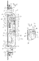
- a sliding leaf lock according to the invention is generally at 10 designated.
- the sliding wing lock 10 comprises a housing 12 and a Lock cuff 14. From openings 16 in the lock cuff 14 protrude like a hook shaped latch 18 emerges, which is in its locked position are located.
- the bolts 18 are rotatable about a pivot pin 20.
- the pivot 20 is at one end of the lever axis shown in dashed lines 22 pivoted lever 24 mounted.
- the pivot 20 opposite end of the lever 24 is fork-shaped and engages around a nut 26 which is in screw engagement with the screw 28 stands.
- the screw 28 is between the one pointing towards the lock mechanism Side of the lock cuff 14 and one from the housing plate Stamping and bending stop 30 received rotatable but fixed held.
- the screw 28 is through a passage 32 in the lock cuff 14 for a tool actuation, for example with a screwdriver, accessible.
- a tool actuation for example with a screwdriver
- the nut 26 becomes Lock cuff 14 or moved away from this.
- Moving the mother 26 along the screw 28 causes the lever 24 to pivot the lever axis 22, whereby the pivot 20 of the bolt 18 on the Lock cuff 14 can be moved to or away from this.
- This is the measure adjustable, how far the bolt 18 in its locked position protrudes from the lock cuff 14.
- a coupling pin 34 of each bolt 18th is each of a fork-like end portion 36 of a coupling element 38 encompassed.
- the lower bar is attached to a bar 18 in FIG. 1 18, from the coupling element of the coupling pin closer to the lock and on each other bolt 18 of the coupling pin 34 further from the faceplate encompassed. It is thereby achieved that the bolt 18 is linear Move the movement of the coupling element 38 in opposite directions.
- the coupling element 38 has elongated holes 40, which are from housing-fixed guide pins 42 are enforced.
- the guide pins 42 guide the coupling element 38 along the arrow P parallel to the plane of the lock cuff 14.
- the coupling element 38 By moving the coupling element 38 in the direction of arrow P. the upper bar 18 swings up and the lower bar 18 swings down, d. H. the bars 18 pivot away from each other.
- the other coupling pin 34 By Engagement of the other coupling pin 34 can be the same Movement of the coupling element 38 a pivoting of the two bars 18 towards each other.
- This option can be chosen if desired, arrange the latches 18 so that the tips of the point hook-like latch 18 away from each other in their locking position.
- Coupling pins 34 on each bolt 18 can be the bolts 18 be pivoted at the same time.
- the coupling element 38 is connected via a nut 44 to move the Locked position driven into the open position.
- the nut 44 has an engagement lug 46, which in a designated engagement lug recess 48 engages on the coupling element 38.
- the engaging nose recess 48 is in the direction of movement of the coupling element 38, d. H. in the direction of arrow P, larger than the width of the Engaging nose 46 in this direction. This becomes a movement game provided that it the latch 18 and thus the coupling element 38th allows from the locked position without moving the nut 44 in to reach the open position.
- the nut 44 also has a square recess 50 into which the shaft (not shown) of a manual control handle 51, such as B. a door handle, or the shaft of an electric motor intervenes.
- the manual control handle 51 is shown in broken lines.
- the nut 44 has a control lug 54, which the engagement lug 46 with respect is opposite the nut axis of rotation 52 and which engages with a reset device 56 is located.
- the reset device 56 has one fork 58 encompassing the control nose 54 and one with the fork 58 and a spring bearing 60 connected tension spring 62. If the nut 44 in Swiveled in the direction of arrow N, the fork 58 is moved upward and the tension spring 62 is stretched. The elastic force of the tension spring 62 sets the nut 44 in the position shown in Fig. 1 after release back, in which the nut 44 abuts the end stop 92.
- the coupling element 38 is via a return element 64, comprising a Compression spring 66, a spring bearing 68 on the coupling element side and a housing-fixed one Spring bearing 70 biased into the locked position.
- a return element 64 comprising a Compression spring 66, a spring bearing 68 on the coupling element side and a housing-fixed one Spring bearing 70 biased into the locked position.
- the sliding leaf lock 10 comprises a locking member 72, which by two locking member guide pins 74 along elongated holes 75 in one orthogonal to the direction of movement P of the coupling element 38 Direction is led.
- the locking member 72 is through the lock bit 76 a profile cylinder lock 78 driven to move.
- the profile cylinder lock 78 is in its key withdrawal position.
- the lock bit 76 secures the locking member 72 in the release position against movement into that shown in FIG. 2 Blocking position.
- the locking member 72 has a trapezoidal locking lug 79, which in the direction of the blocking member 72 lying in the plane of the drawing projecting towards the viewer.
- the blocking position of the blocking element 72 shown in FIG. 1 is in FIG. 2 shown.
- the locking member 72 was opened by turning the lock bit 76 in Direction of the closing cuff 14 in the shut-off recess 88 of the coupling element 38 moves.
- the profiled spring element 84 that the Housing 12 is riveted, is locked in the locking position detent 82.
- the profile cylinder lock 78 is again in its key withdrawal position.
- the locking bit 76 abuts the locking member 72 in such a way that movement of the locking member 72 into the release position is safe is prevented.
- Fig. 3 is the sliding wing lock 10 shown in Fig. 1 with the bolts 18 and the coupling element 38 shown in the open position.
- the Nut 44 is turned up to end stop 90 in the direction of arrow N.
- the fork-like end section 36 also abuts the end stop 90.
- the Bolts 18 are pivoted away from one another and thus give openings 94 of a striking plate 96 free, which in the locking position of the hook-like Bolt 18 was attacked by these.
- the rear grip is the tip of the upper bar 18 in its Locked position indicated by dashed lines.
- FIGS. 1 to 3 is another embodiment of the present invention shown.
- the same components as in FIGS. 1 to 3 are the same Provided reference numerals, but increased by the number 100.
- the embodiment 4 will only be described insofar as it differs from the previously described embodiment differs. Otherwise it will be on the description of FIGS. 1 to 3 referenced.
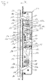
- FIG. 4 shows a situation in which the sliding leaf lock 110 in the direction of arrow B on a wing connection element, for example a door frame, attached striking plate 196 is moved.
- a wing connection element for example a door frame
- attached striking plate 196 is moved.
- the bolts 118 with those formed on them in the area of the hook tips Drafts 118a on edges 198 at openings 194 of the strike plate 196.
- the bars 118 are pivoted away from each other.
- the coupling element 138 moves in the direction arrow P down.
- Because of the compared to the engagement nose 146 larger dimension in the direction of arrow P of the engagement nose recess 148 becomes the engagement lug 146 of the nut 144 from the coupling element 138 but not moved.
- the nut 144 and one connected to it Manual control element therefore remains in the through the reset device 156 and the end stop 192 defined basic position.
- FIGS. 1 to 3 Another difference between that shown in Figs. 1 to 3 Embodiment is that the coupling pin 134 on the coupling element are provided and coupling recesses 137 on the bolts 118 can be encompassed. Like the coupling pin 34 in FIGS. 1 to 3 are the coupling recesses at the same distance from the pivot pin 120 arranged, this being exactly between the two coupling recesses 137 of each latch 118 is provided.
- FIG. 4 In the embodiment shown in Fig. 4 is compared to that previous the adjustability of the exit depth of the latch 118 from the Openings 116 of the lock cuff 114 are designed differently.
- a rotatably but axially fixed screw 128 is as in the embodiment of FIGS. 1 to 3, between the lock cuff 114 and held a stop 130.
- FIG. 4 is only the top screw 128 to be seen completely, since the lower screw 128 is partially through the coupling element 138 is covered.
- An internally threaded one Carriage 125 is in screw engagement with screw 128. Through Rotation of the screw 128 allows the carriage 125 on the lock cuff 114 to be moved to or away from this.
- the carriage 125 has one Cantilever 125a on which the pivot 120 of the bolt 118 is attached is. Thus, with the slide 125, the bolt 118 is also on the lock cuff moved to or away from this.
- the locking member 172 points in the direction of Arrow P has a smaller dimension than that shown in FIGS. 1 to 3 Embodiment.
- the locking pin 186 is at the top End of the locking member 172 provided. In the locked position, which is identical to the locking position in FIGS. 1 to 4 is moved into the shut-off recess 188 of the coupling element 138 become.
- the lock bit 176 of a cylinder lock 178 is moved into the locked position in the previously described embodiment.
- 5 to 7 show an embodiment of the invention Sliding wing lock, which is essentially that shown in FIG. 4 Embodiment corresponds.
- the same components as in the previously explained 1 to 4 are provided with the same reference numerals in FIGS. 5 to 7.
- 5 to 7 will continue to be described only to the extent that they are components included, which have not already been explained in one of FIGS. 1 to 4. Otherwise is expressly made to the description of FIGS. 1 to 4.
- the sliding wing lock 210 includes a mis-switching device that prevents the bolt 218 from opening when the sliding sash is open Movement from its locked or locked position to its open position can be locked.
- This mis-switching device includes a substantially triangular proximity switch 203 that is pivotally mounted on a guide pin 242 around the latter. A peak 203a of the proximity switch 203 protrudes from an opening 217 in the lock cuff 214 out.
- a stop 205 provided, which bears against the inside of the lock cuff 214. He is pressed against this by the elastic force of the spring 207.
- the Spring 207 is supported with a cantilever 207a on the end stop 292 the nut 244 off.
- a helical shape adjoins the arm 207a Spring section 207b, which another, from the aforementioned surrounds different guide pin 242. This guide pin 242 holds the Spring 207 in place.
- the helical spring section 207b in turn closes Return boom 207c, the end portion of which at the tip 203a opposite side of the proximity switch 203 and so the Stop 205 of the proximity switch 203 against the inside of the lock cuff 214 presses and the proximity switch 203 in that shown in FIG Holds position.
- the position of the proximity switch 203 is such that one of the Tip 203a towards the lock cuff 214, i.e. contrary to In the direction of the arrow B, the solder that is felled stores the proximity sensor 203 Guide pin 242 does not cut. This will then when closing of the sliding wing, the tip 203a against the wall 298 of the striking plate 296 strikes, the closing button on the proximity switch 203 moving into the housing 212 of the sliding wing lock 210 Torque exerted on the proximity switch 203.
- a blocking extension 209 is formed, with which the locking pin 286 of the locking member 272 in the case of an attempt a locking of the sliding wing lock collides. So it is not possible, the locking member 272 by the lock bit 276 of the cylinder lock 278 to move to its locked position, i.e. the locking pin 286 to be inserted into the shut-off recess 288 of the coupling element 238, as long as the proximity switch 203 with the blocking extension 209 in the blocking position shown in FIG. 5.
- FIG. 6 shows the blocking effect of the blocking extension 209.
- the lock bit 276 can be moved with the locking member Turn 272 until the locking pin 286 on the blocking extension 209 is applied.
- the cam lock 276 is inserted into the cylinder lock 278 inserted key (not shown) applied with additional force, this only leads to the stop 205 having a larger one There is pressure against the inside of the lock cuff 214.
- a locking member resting on the blocking extension 209 does not impair the function of the fail-safe device, at least if when pushing or pushing the sliding sash in the key Profile cylinder lock 278 is released. If the tip 203a of the approximation stater 203 on a wing connection element, for example on the Wall 298 of the striking plate 296 strikes and the sliding leaf or the sliding wing lock 210 is moved further in the direction of arrow B, so the proximity switch is in the housing 212 of the sliding wing lock 210 pivoted in, the blocking extension 209 a force on the exerts on locking pin 286 and the locking member 272 back in the position shown in Fig. 5. If it continues Locking movement, the blocking extension 209 is pivoted even further and finally releases the movement of the locking member into the locking position.
- Fig. 7 the sliding leaf lock 210 is locked with the striking plate 296 shown.
- the proximity switch 203 rests with its tip 203a the wall 298 of the striking plate 296 and is against the force of the spring 207 pivoted into the housing 212.
- the pivoting movement of the Proximity button 203 causes the return boom to shift 207c of the spring 207.
- the blocking extension 209 is pivoted such that it movement of the locking pin 286 of the locking member 272 into the shut-off recess 288 of the coupling element 238.
- the locking member 272 can accordingly be brought into its locked position in which it the latch 218 locked with the striking plate 296 against movement locked in their open position.
- FIGS. 5 to 7 Another difference between the embodiment of FIGS. 5 to 7 and the embodiments of FIGS. 1 to 4 lies in the structural design the return element 264 and the reset device 256 the return device 256 becomes a compression spring 263 as a return spring used.
- the compression spring rests at its end facing the nut 244 263 on a housing-fixed spring bearing 260.
- the control lug 254 encompassing fork 258 has a cantilever which holds the compression spring 263 engages and a fork-side spring bearing 259 for the the nut 244 forms the pointing end of the compression spring 263.
- the return element 264 uses a tension spring 267, which with a ring-like design of the spring wire at both ends in one coupling element-side spring bearing 268 and a housing-fixed spring bearing 270 is attached.
Landscapes
- Lock And Its Accessories (AREA)
- Wing Frames And Configurations (AREA)
- Hinge Accessories (AREA)
- Image-Pickup Tubes, Image-Amplification Tubes, And Storage Tubes (AREA)
- Special Wing (AREA)
Abstract
Description
- Fig. 1
- eine Seitenansicht einer ersten Ausführungsform des erfindungsgemäßen Schiebeflügelschlosses in der Verrastungsstellung,
- Fig. 2
- eine Detailansicht des in Fig. 1 gezeigten Sperrglieds in der Sperrstellung,
- Fig. 3
- eine Seitenansicht des in Fig. 1 gezeigten Schiebeflügelschlosses in seiner Öffnungsstellung,
- Fig. 4
- eine weitere Ausführungsform des erfindungsgemäßen Schiebeflügelschlosses während eines Verrastungsvorgangs an einem Schließblech,
- Fig. 5
- eine im Wesentlichen der Ausführungsform der Fig. 4 entsprechende, weitere Ausführungsform eines erfindungsgemäßen Schiebeflügelschlosses mit Fehlschaltsicherung,
- Fig. 6
- eine Detailansicht des Blockierens des Sperrglieds durch die in Fig. 5 gezeigte Fehlschaltsicherung sowie
- Fig. 7
- die in Fig. 5 gezeigte Ausführungsform nach Verrasten des Schiebeflügelschlosses an einem Schließblech.
Claims (27)
- Schiebeflügelschloss zur Verrastung und Verriegelung eines Schiebeflügels, vorzugsweise einer Schiebetür, mit einem Flügelanschlusselement (96; 196; 296), wobei das Schiebeflügelschloss umfasst:dadurch gekennzeichnet, dass die wenigstens zwei Riegel (18; 118; 218) zur selbsttätigen Bewegung von ihrer Öffnungsstellung in ihre Verrastungsstellung vorgespannt sind, und dass das Schiebeflügelschloss (10; 110; 210) ein zwischen einer Sperrstellung und einer Freigabestellung bewegbares Sperrglied (72; 172; 272) umfasst, welches in seiner Sperrstellung eine Bewegung der Riegel (18; 118; 218) von einer Verriegelungsstellung, in welcher sie in die wenigstens eine Öffnung (94; 194; 294) am Flügelanschlusselement (96; 196; 296) eingreifen, in die Öffnungsstellung hemmt und in seiner Freigabestellung eine Bewegung der Riegel (18; 118; 218) aus der Verriegelungsstellung und aus der Verrastungsstellung in die Öffnungsstellung zulässt.wenigstens zwei Riegel (18; 118; 218), welche durch wenigstens ein im Wesentlichen linear bewegliches Kopplungselement (38; 138; 238) gekoppelt sind zur gemeinsamen Bewegung zwischen einer Verrastungstellung, in welcher die Riegel (18; 118; 218) bei geschlossenem Schiebeflügel in wenigstens eine Öffnung (94; 194; 294) am Flügelanschlusselement (96; 196; 296) eine Öffnungsbewegung des Schiebeflügels blockierend eingreifen, und einer Öffnungsstellung, in welcher die Riegel (18; 118; 218) bei geschlossenem Schiebeflügel die wenigstens eine Öffnung (94; 194; 294) freigeben, undein Getriebe (38, 44; 138, 144; 238, 244) mit einem mit einem Betätigungselement (51) koppelbaren Eingangselement (44; 144; 244) zur Bewegung der wenigstens zwei Riegel (18; 118; 218) aus der Verrastungsstellung in die Öffnungsstellung,
- Schiebeflügelschloss nach Anspruch 1, dadurch gekennzeichnet, dass die Vorspannung der wenigstens zwei Riegel (18; 118; 218) in ihre Verrastungsstellung durch die elastische Rückholkraft wenigstens eines Rückhol-Federelements (64; 164; 264) erfolgt.
- Schiebeflügelschloss nach Anspruch 1 oder 2, dadurch gekennzeichnet, dass das Sperrglied (72; 172; 272) mit einer schlüsselbetätigbaren Schlosseinheit (78; 178; 278) verkoppelt ist.
- Schiebeflügelschloss nach Anspruch 3, dadurch gekennzeichnet, dass die Schlosseinheit (78; 178; 278) einen Profilzylinder (78; 178; 278) aufweist, durch dessen Schließbart (76; 176; 276) das Sperrglied (72; 172; 272) von der Sperr- oder Freigabestellung in die jeweils andere Stellung bewegbar ist.
- Schiebeflügelschloss nach einem der vorhergehenden Ansprüche, dadurch gekennzeichnet, dass das Sperrglied (72; 172; 272) in seiner Sperrstellung unmittelbar an das Kopplungselement (38; 138; 238) angreift.
- Schiebeflügelschloss nach einem der vorhergehenden Ansprüche, dadurch gekennzeichnet, dass das Sperrglied (72; 172; 272) in seiner Sperrstellung wenigstens teilweise in eine Sperrausnehmung (88; 188; 288) des wenigstens einen Kopplungselements (38; 138; 238) eingreift.
- Schiebeflügelschloss nach einem der vorhergehenden Ansprüche, dadurch gekennzeichnet, dass die Verriegelungsstellung mit der Verrastungsstellung identisch ist.
- Schiebeflügelschloss nach einem der vorhergehenden Ansprüche, dadurch gekennzeichnet, dass das Sperrglied (72; 172; 272) wenigstens eine überwindbare Verrastung (79, 80, 82, 84; 179, 180, 182, 184; 279, 280, 282, 284) aufweist, welche es in wenigstens einer seiner Stellungen: Sperrstellung und Freigabestellung, vorzugsweise in beiden Stellungen, hält.
- Schiebeflügelschloss nach Anspruch 8, dadurch gekennzeichnet, dass die wenigstens eine Verrastung (79, 80, 82, 84; 179, 180, 182, 184; 279, 280, 282, 284) durch wenigstens eine Rast-Einsenkung oder wenigstens eine Rastnase (79; 179; 279) gebildet ist, an die ein profiliertes Verrastungsfederelement (84; 184; 284) angreift.
- Schiebeflügelschloss nach einem der vorhergehenden Ansprüche, dadurch gekennzeichnet, dass das Sperrglied (72; 172; 272) durch eine im Wesentlichen lineare Verschiebebewegung quer zur Bewegungsrichtung (P) des Kopplungselements (38; 138; 238) zwischen seinen beiden Stellungen: Sperrstellung und Freigabestellung, bewegbar ist.
- Schiebeflügelschloss nach einem der Ansprüche 4 bis 10, dadurch gekennzeichnet, dass der Schließbart (76; 176; 276) in einer Schlüsselabzugsstellung der Schlosseinheit (78; 178; 278) das Sperrglied (72; 172; 272) in wenigstens einer seiner Stellungen: Sperrstellung und Freigabestellung, vorzugsweise in beiden Stellungen, gegen eine Bewegung in Richtung der jeweils anderen Stellung sichert.
- Schiebeflügelschloss nach einem der vorhergehenden Ansprüche, dadurch gekennzeichnet, dass das Getriebe (38, 44; 138, 144; 238, 244) eine mit diesem verkoppelte Nuss (44; 144; 244) als Eingangselement sowie das Kopplungselement (38; 138; 238) umfasst.
- Schiebeflügelschloss nach Anspruch 12, dadurch gekennzeichnet, dass die Nuss (44; 144; 244) derart mit Bewegungsspiel mit dem Kopplungselement (38; 138; 238) verkoppelt ist, dass das wenigstens eine Kopplungselement (38; 138; 238) von der Verrastungsstellung in die Öffnungsstellung ohne Mitbewegung der Nuss (44; 144; 244) bewegbar ist.
- Schiebeflügelschloss nach Anspruch 12 oder 13, dadurch gekennzeichnet, dass die Nuss (44; 144; 244) eine Eingriffsnase (46; 146; 246) aufweist, welche in eine Eingriffsausnehmung (48; 148; 248) des wenigstens einen Kopplungselements (38; 138; 238) eingreift.
- Schiebeflügelschloss nach einem der Ansprüche 12 bis 14, dadurch gekennzeichnet, dass die Nuss (44; 144; 244) eine Steuernase (54; 154; 254) aufweist, welche formschlüssig mit einer Rückstellvorrichtung (56; 156; 256) gekoppelt ist.
- Schiebeflügelschloss nach einem der vorhergehenden Ansprüche, dadurch gekennzeichnet, dass die wenigstens zwei Riegel (18; 118; 218) als Haken ausgebildet sind.
- Schiebeflügelschloss nach einem der vorhergehenden Ansprüche, dadurch gekennzeichnet, dass die wenigstens zwei Riegel (18; 118; 218) schwenkbar, vorzugsweise gegenläufig schwenkbar, im Schiebeflügelschloss (10; 110; 210) gelagert sind.
- Schiebeflügelschloss nach einem der vorhergehenden Ansprüche, dadurch gekennzeichnet, dass das Maß, wie weit die wenigstens zwei Riegel (18; 118; 218) in ihrer Verriegelungsstellung aus dem Schloss (10; 110; 210) heraustreten, einstellbar ist, vorzugsweise für jeden Riegel (18; 118; 218) unabhängig von dem wenigstens einen anderen Riegel (18; 118; 218).
- Schiebeflügelschloss nach Anspruch 18, dadurch gekennzeichnet, dass es wenigstens einen um einen Drehpunkt (22) drehbaren Hebel (24) aufweist, an dessen einem Ende ein Riegel (18) schwenkbar gelagert ist und dessen anderes Ende mit einem von einer Schlossaußenseite her bedienbaren Spindel- bzw. Gewindetriebs (26, 28, 30) verbunden ist.
- Schiebeflügelschloss nach Anspruch 18, dadurch gekennzeichnet, dass wenigstens einer der Riegel (118; 218) drehbar an einem Positionierungselement (125; 225) gelagert ist, welches linear in einer Richtung im Wesentlichen orthogonal zu der Seitenfläche des Schlosses (110; 210) beweglich ist, aus welcher der wenigstens eine Riegel (118; 218) austritt.
- Schiebeflügelschloss nach einem der Ansprüche 2 bis 20, dadurch gekennzeichnet, dass das Rückhol-Federelement (64; 164; 264) am Kopplungselement (38; 138; 238) angreift.
- Schiebeflügelschloss nach einem der vorhergehenden Ansprüche, dadurch gekennzeichnet, dass es eine Fehlschaltsicherung (203, 205, 207, 209, 217) umfasst, welche zur Verhinderung der Verriegelung der wenigstens zwei Riegel (218) eine Bewegung des Sperrglieds (272) in seine Sperrstellung zumindest solange unterbindet, bis wenigstens ein Element (203) des Schiebeflügels beim Schließen des Schiebeflügels erstmals mit dem Flügelanschlusselement (296) zusammenwirkt.
- Schiebeflügelschloss nach Anspruch 22, dadurch gekennzeichnet, dass die Fehlschaltsicherung (203, 205, 207, 209, 217) einen die Verriegelbarkeit der wenigstens zwei Riegel (218) steuernden, beweglichen Näherungstaster (203) aufweist, der beim Schließen des Schiebeflügels an dem Flügelanschlusselement (296) anschlägt und nach dem Anschlagen bei fortgesetzter Schließbewegung des Schiebeflügels seine Lage relativ zu diesem in Abhängigkeit des Abstands zwischen Schiebeflügel und Flügelanschlusselement (296) verändert.
- Schiebeflügelschloss nach Anspruch 23, dadurch gekennzeichnet, dass die Fehlschaltsicherung (203, 205, 207, 209, 217) ein mit dem Näherungstaster (203) bewegungsgekoppeltes Blockiermittel (209) umfasst, welches eine Bewegung des Sperrglieds (272) in seine Sperrstellung in Abhängigkeit von der Lage des Näherungstasters (203) relativ zum Schiebeflügel zulässt.
- Schiebeflügelschloss nach Anspruch 24, dadurch gekennzeichnet, dass das Blockiermittel (209) einstückig mit dem Näherungstaster (203) ausgebildet ist.
- Schiebeflügelschloss nach einem der Ansprüche 23 bis 25, dadurch gekennzeichnet, dass der Näherungstaster (203) schwenkbar, vorzugsweise gegen die elastische Kraft einer Rückstellfeder (207) schwenkbar, gelagert ist.
- Schiebeflügelschloss, welches der Verrastung und Verriegelung eines Schiebeflügels, vorzugsweise einer Schiebetür, mit einem Flügelanschlusselement (96; 196; 296) dient, umfassend:wenigstens ein Riegel (18; 118; 218), welcher bewegbar ist zwischen einer Verrastungsstellung, in welcher bei geschlossenem Schiebeflügel der wenigstens eine Riegel (18; 118; 218) in wenigstens eine Öffnung (94; 194; 294) am Flügelanschlusselement (96; 196; 296) eine Öffnungsbewegung des Schiebeflügels blockierend eingreift, und einer Öffnungsstellung, in welcher bei geschlossenem Schiebeflügel der wenigstens eine Riegel (18; 118; 218) die wenigstens eine Öffnung (94; 194; 294) freigibt, wobei der wenigstens eine Riegel (18; 118; 218) in seine Verrastungsstellung vorgespannt und in dieser gegen eine Bewegung in seine Öffnungsstellung verriegelbar ist,ein Sperrglied (72; 172; 272), welches bewegbar ist zwischen einer Sperrstellung, in welcher es den wenigstens einen Riegel (18; 118; 218) gegen eine Bewegung in seine Öffnungsstellung verriegelt, und einer Freigabestellung, in welcher die Bewegung des wenigstens einen Riegels (18; 118; 218) in seine Öffnungsstellung zugelassen ist,eine Fehlschaltsicherung (203, 205, 207, 209, 217), welche zur Verhinderung der Verriegelung des wenigstens einen Riegels (218) eine Bewegung des Sperrglieds (272) in seine Sperrstellung zumindest solange unterbindet, bis wenigstens ein Element (203) des Schiebeflügels beim Schließen des Schiebeflügels erstmals mit dem Flügelanschlusselement (296) zusammenwirkt.
Applications Claiming Priority (2)
| Application Number | Priority Date | Filing Date | Title |
|---|---|---|---|
| DE10058945A DE10058945A1 (de) | 2000-11-28 | 2000-11-28 | Schiebeflügelschloss |
| DE10058945 | 2000-11-28 |
Publications (2)
| Publication Number | Publication Date |
|---|---|
| EP1209307A1 true EP1209307A1 (de) | 2002-05-29 |
| EP1209307B1 EP1209307B1 (de) | 2005-12-21 |
Family
ID=7664906
Family Applications (1)
| Application Number | Title | Priority Date | Filing Date |
|---|---|---|---|
| EP01102594A Expired - Lifetime EP1209307B1 (de) | 2000-11-28 | 2001-02-06 | Schiebeflügelschloss |
Country Status (4)
| Country | Link |
|---|---|
| EP (1) | EP1209307B1 (de) |
| AT (1) | ATE313678T1 (de) |
| DE (2) | DE10058945A1 (de) |
| ES (1) | ES2250236T3 (de) |
Cited By (6)
| Publication number | Priority date | Publication date | Assignee | Title |
|---|---|---|---|---|
| WO2005124070A1 (en) * | 2004-06-22 | 2005-12-29 | Bradnam's Windows & Doors Pty Ltd | A lock for a window or door |
| AU2011101046B4 (en) * | 2011-08-16 | 2012-04-12 | Asia Pacific Trading (Aust) Pty Ltd | Locking mechanism |
| EP1740791A4 (de) * | 2004-04-16 | 2014-07-02 | Southco | Hakenfalle |
| CN111173386A (zh) * | 2020-02-28 | 2020-05-19 | 南京康尼机电股份有限公司 | 一种内置塞拉门用辅助手动压紧锁 |
| CN112252843A (zh) * | 2020-08-24 | 2021-01-22 | 春光五金有限公司 | 具备自锁功能的窗户锁 |
| WO2025091075A1 (en) * | 2023-10-31 | 2025-05-08 | Aluminium Specialties Group Pty. Ltd. | Sliding door lock |
Families Citing this family (3)
| Publication number | Priority date | Publication date | Assignee | Title |
|---|---|---|---|---|
| DE202008004173U1 (de) | 2008-03-26 | 2009-08-06 | Hoppe Ag, St. Martin | Verriegelungsvorrichtung |
| US11591835B2 (en) * | 2021-03-10 | 2023-02-28 | Qianyan Cheng | Narrow backset auto-latching mortise lock for sliding door |
| DE102022123534A1 (de) * | 2022-09-14 | 2024-03-14 | Gebr. Willach Gmbh | Schlossvorrichtung für eine Schiebetür sowie Schlosssystem |
Citations (4)
| Publication number | Priority date | Publication date | Assignee | Title |
|---|---|---|---|---|
| GB2130287A (en) * | 1982-07-17 | 1984-05-31 | Gkn Crompton | Door fastener |
| GB2168748A (en) * | 1984-12-07 | 1986-06-25 | Michael Leonard Smith | Latch mechanism for sliding doors |
| GB2212849A (en) * | 1987-11-25 | 1989-08-02 | Goodwin W J & Son Ltd | Locking assembly hookbolts |
| US5820170A (en) * | 1997-01-21 | 1998-10-13 | Sash Controls, Inc. | Multi-point sliding door latch |
Family Cites Families (1)
| Publication number | Priority date | Publication date | Assignee | Title |
|---|---|---|---|---|
| DE1152037B (de) * | 1961-09-21 | 1963-07-25 | Tiefenthal Geb | Tuerschloss fuer Faltschiebetueren |
-
2000
- 2000-11-28 DE DE10058945A patent/DE10058945A1/de not_active Withdrawn
-
2001
- 2001-02-06 AT AT01102594T patent/ATE313678T1/de not_active IP Right Cessation
- 2001-02-06 DE DE50108448T patent/DE50108448D1/de not_active Expired - Lifetime
- 2001-02-06 ES ES01102594T patent/ES2250236T3/es not_active Expired - Lifetime
- 2001-02-06 EP EP01102594A patent/EP1209307B1/de not_active Expired - Lifetime
Patent Citations (4)
| Publication number | Priority date | Publication date | Assignee | Title |
|---|---|---|---|---|
| GB2130287A (en) * | 1982-07-17 | 1984-05-31 | Gkn Crompton | Door fastener |
| GB2168748A (en) * | 1984-12-07 | 1986-06-25 | Michael Leonard Smith | Latch mechanism for sliding doors |
| GB2212849A (en) * | 1987-11-25 | 1989-08-02 | Goodwin W J & Son Ltd | Locking assembly hookbolts |
| US5820170A (en) * | 1997-01-21 | 1998-10-13 | Sash Controls, Inc. | Multi-point sliding door latch |
Cited By (6)
| Publication number | Priority date | Publication date | Assignee | Title |
|---|---|---|---|---|
| EP1740791A4 (de) * | 2004-04-16 | 2014-07-02 | Southco | Hakenfalle |
| WO2005124070A1 (en) * | 2004-06-22 | 2005-12-29 | Bradnam's Windows & Doors Pty Ltd | A lock for a window or door |
| AU2011101046B4 (en) * | 2011-08-16 | 2012-04-12 | Asia Pacific Trading (Aust) Pty Ltd | Locking mechanism |
| CN111173386A (zh) * | 2020-02-28 | 2020-05-19 | 南京康尼机电股份有限公司 | 一种内置塞拉门用辅助手动压紧锁 |
| CN112252843A (zh) * | 2020-08-24 | 2021-01-22 | 春光五金有限公司 | 具备自锁功能的窗户锁 |
| WO2025091075A1 (en) * | 2023-10-31 | 2025-05-08 | Aluminium Specialties Group Pty. Ltd. | Sliding door lock |
Also Published As
| Publication number | Publication date |
|---|---|
| ES2250236T3 (es) | 2006-04-16 |
| DE50108448D1 (de) | 2006-01-26 |
| DE10058945A1 (de) | 2002-05-29 |
| ATE313678T1 (de) | 2006-01-15 |
| EP1209307B1 (de) | 2005-12-21 |
Similar Documents
| Publication | Publication Date | Title |
|---|---|---|
| EP0668425B1 (de) | Türschloss | |
| EP0907816B1 (de) | Verschluss für türen, hauben, klappen od. dgl., insbesondere von fahrzeugen, wie kraftfahrzeugen | |
| DE102012111085B4 (de) | Türöffner | |
| DE10209573A1 (de) | Treibstangenverschluss für eine Schiebetür | |
| EP0945572B1 (de) | Türschlossanordnung, vorzugweise Treibstangenschlossanordnung | |
| EP0907815B1 (de) | Verschluss für türen, hauben, klappen od. dgl., insbesondere von fahrzeugen, wie kraftfahrzeugen | |
| EP2031162B1 (de) | Selbstverriegelndes Türschloss | |
| EP0634543B1 (de) | Zahlenkombinationsschloss mit einem Drehknopf, mit einer Nockenscheibe und mit einem Einfallhebel | |
| EP0954667B1 (de) | Schloss mit falle für tür oder fenster | |
| EP1209307B1 (de) | Schiebeflügelschloss | |
| EP2206858B1 (de) | Türschloss | |
| DE4114007C2 (de) | Treibstangenverschluß | |
| DE19522641A1 (de) | Schließeinrichtung mit Flügelfangeinrichtung | |
| EP0848124B1 (de) | Schloss mit Falle und Riegel | |
| EP2666938B1 (de) | Schloss für eine tür | |
| DE102006043549B4 (de) | Schließ- und Öffnungsanlage zur Sicherung eines schwenkbaren Türflügels in einer Bauwerksöffnung gegen ein unberechtigtes Öffnen | |
| DE3007304A1 (de) | Elektrischer schalter, insbesondere fuer ein elektrisches handwerkzeug | |
| DE10125915B4 (de) | Fehlbedienungssicheres Schiebeflügel- oder Schwenkflügelschloss | |
| EP1309765A1 (de) | Sicherungsvorrichtung, beispielsweise kindersicherung sowie schliesseinrichtung mit einer solchen sicherungsvorrichtung | |
| EP2322744A1 (de) | Schloss, Schwenkhaken-Schloss und Verriegelungssystem, insbesondere zur Mehrpunkt-Verriegelung, für eine Tür oder ein Fenster | |
| EP0098364B1 (de) | Beschlag für einen kipp- und nachfolgend mindestens parallelabstellbaren Flügel eines Fensters, einer Tür od. dgl. | |
| EP1672153B1 (de) | Schloss mit Riegel und Riegelantrieb | |
| EP0974721B1 (de) | Mehrriegelschloss | |
| DE3831529A1 (de) | Treibstangenverschluss | |
| DE8216056U1 (de) | Fallen-panikschloss |
Legal Events
| Date | Code | Title | Description |
|---|---|---|---|
| PUAI | Public reference made under article 153(3) epc to a published international application that has entered the european phase |
Free format text: ORIGINAL CODE: 0009012 |
|
| AK | Designated contracting states |
Kind code of ref document: A1 Designated state(s): AT BE CH CY DE DK ES FI FR GB GR IE IT LI LU MC NL PT SE TR |
|
| AX | Request for extension of the european patent |
Free format text: AL;LT;LV;MK;RO;SI |
|
| 17P | Request for examination filed |
Effective date: 20021128 |
|
| AKX | Designation fees paid |
Designated state(s): AT BE CH CY DE DK ES FI FR GB GR IE IT LI LU MC NL PT SE TR |
|
| 17Q | First examination report despatched |
Effective date: 20050111 |
|
| GRAP | Despatch of communication of intention to grant a patent |
Free format text: ORIGINAL CODE: EPIDOSNIGR1 |
|
| GRAS | Grant fee paid |
Free format text: ORIGINAL CODE: EPIDOSNIGR3 |
|
| GRAA | (expected) grant |
Free format text: ORIGINAL CODE: 0009210 |
|
| AK | Designated contracting states |
Kind code of ref document: B1 Designated state(s): AT BE CH CY DE DK ES FI FR GB GR IE IT LI LU MC NL PT SE TR |
|
| PG25 | Lapsed in a contracting state [announced via postgrant information from national office to epo] |
Ref country code: IT Free format text: LAPSE BECAUSE OF FAILURE TO SUBMIT A TRANSLATION OF THE DESCRIPTION OR TO PAY THE FEE WITHIN THE PRESCRIBED TIME-LIMIT;WARNING: LAPSES OF ITALIAN PATENTS WITH EFFECTIVE DATE BEFORE 2007 MAY HAVE OCCURRED AT ANY TIME BEFORE 2007. THE CORRECT EFFECTIVE DATE MAY BE DIFFERENT FROM THE ONE RECORDED. Effective date: 20051221 Ref country code: NL Free format text: LAPSE BECAUSE OF FAILURE TO SUBMIT A TRANSLATION OF THE DESCRIPTION OR TO PAY THE FEE WITHIN THE PRESCRIBED TIME-LIMIT Effective date: 20051221 Ref country code: IE Free format text: LAPSE BECAUSE OF FAILURE TO SUBMIT A TRANSLATION OF THE DESCRIPTION OR TO PAY THE FEE WITHIN THE PRESCRIBED TIME-LIMIT Effective date: 20051221 Ref country code: FI Free format text: LAPSE BECAUSE OF FAILURE TO SUBMIT A TRANSLATION OF THE DESCRIPTION OR TO PAY THE FEE WITHIN THE PRESCRIBED TIME-LIMIT Effective date: 20051221 |
|
| REG | Reference to a national code |
Ref country code: GB Ref legal event code: FG4D Free format text: NOT ENGLISH |
|
| REG | Reference to a national code |
Ref country code: CH Ref legal event code: EP |
|
| REG | Reference to a national code |
Ref country code: IE Ref legal event code: FG4D Free format text: LANGUAGE OF EP DOCUMENT: GERMAN |
|
| REF | Corresponds to: |
Ref document number: 50108448 Country of ref document: DE Date of ref document: 20060126 Kind code of ref document: P |
|
| GBT | Gb: translation of ep patent filed (gb section 77(6)(a)/1977) |
Effective date: 20060108 |
|
| PG25 | Lapsed in a contracting state [announced via postgrant information from national office to epo] |
Ref country code: AT Free format text: LAPSE BECAUSE OF NON-PAYMENT OF DUE FEES Effective date: 20060206 |
|
| PG25 | Lapsed in a contracting state [announced via postgrant information from national office to epo] |
Ref country code: CH Free format text: LAPSE BECAUSE OF NON-PAYMENT OF DUE FEES Effective date: 20060228 Ref country code: BE Free format text: LAPSE BECAUSE OF NON-PAYMENT OF DUE FEES Effective date: 20060228 Ref country code: LU Free format text: LAPSE BECAUSE OF NON-PAYMENT OF DUE FEES Effective date: 20060228 Ref country code: LI Free format text: LAPSE BECAUSE OF NON-PAYMENT OF DUE FEES Effective date: 20060228 Ref country code: MC Free format text: LAPSE BECAUSE OF NON-PAYMENT OF DUE FEES Effective date: 20060228 |
|
| PG25 | Lapsed in a contracting state [announced via postgrant information from national office to epo] |
Ref country code: DK Free format text: LAPSE BECAUSE OF FAILURE TO SUBMIT A TRANSLATION OF THE DESCRIPTION OR TO PAY THE FEE WITHIN THE PRESCRIBED TIME-LIMIT Effective date: 20060321 Ref country code: GR Free format text: LAPSE BECAUSE OF FAILURE TO SUBMIT A TRANSLATION OF THE DESCRIPTION OR TO PAY THE FEE WITHIN THE PRESCRIBED TIME-LIMIT Effective date: 20060321 Ref country code: SE Free format text: LAPSE BECAUSE OF FAILURE TO SUBMIT A TRANSLATION OF THE DESCRIPTION OR TO PAY THE FEE WITHIN THE PRESCRIBED TIME-LIMIT Effective date: 20060321 |
|
| REG | Reference to a national code |
Ref country code: ES Ref legal event code: FG2A Ref document number: 2250236 Country of ref document: ES Kind code of ref document: T3 |
|
| PG25 | Lapsed in a contracting state [announced via postgrant information from national office to epo] |
Ref country code: PT Free format text: LAPSE BECAUSE OF FAILURE TO SUBMIT A TRANSLATION OF THE DESCRIPTION OR TO PAY THE FEE WITHIN THE PRESCRIBED TIME-LIMIT Effective date: 20060522 |
|
| NLV1 | Nl: lapsed or annulled due to failure to fulfill the requirements of art. 29p and 29m of the patents act | ||
| REG | Reference to a national code |
Ref country code: IE Ref legal event code: FD4D |
|
| ET | Fr: translation filed | ||
| REG | Reference to a national code |
Ref country code: CH Ref legal event code: PL |
|
| PLBE | No opposition filed within time limit |
Free format text: ORIGINAL CODE: 0009261 |
|
| STAA | Information on the status of an ep patent application or granted ep patent |
Free format text: STATUS: NO OPPOSITION FILED WITHIN TIME LIMIT |
|
| 26N | No opposition filed |
Effective date: 20060922 |
|
| BERE | Be: lapsed |
Owner name: AUG. WINKHAUS G.M.B.H. & CO. KG Effective date: 20060228 |
|
| PGFP | Annual fee paid to national office [announced via postgrant information from national office to epo] |
Ref country code: GB Payment date: 20080219 Year of fee payment: 8 |
|
| PG25 | Lapsed in a contracting state [announced via postgrant information from national office to epo] |
Ref country code: TR Free format text: LAPSE BECAUSE OF FAILURE TO SUBMIT A TRANSLATION OF THE DESCRIPTION OR TO PAY THE FEE WITHIN THE PRESCRIBED TIME-LIMIT Effective date: 20051221 |
|
| PGFP | Annual fee paid to national office [announced via postgrant information from national office to epo] |
Ref country code: FR Payment date: 20080215 Year of fee payment: 8 |
|
| PG25 | Lapsed in a contracting state [announced via postgrant information from national office to epo] |
Ref country code: CY Free format text: LAPSE BECAUSE OF FAILURE TO SUBMIT A TRANSLATION OF THE DESCRIPTION OR TO PAY THE FEE WITHIN THE PRESCRIBED TIME-LIMIT Effective date: 20051221 |
|
| PGFP | Annual fee paid to national office [announced via postgrant information from national office to epo] |
Ref country code: ES Payment date: 20090205 Year of fee payment: 9 |
|
| GBPC | Gb: european patent ceased through non-payment of renewal fee |
Effective date: 20090206 |
|
| REG | Reference to a national code |
Ref country code: FR Ref legal event code: ST Effective date: 20091030 |
|
| PG25 | Lapsed in a contracting state [announced via postgrant information from national office to epo] |
Ref country code: FR Free format text: LAPSE BECAUSE OF NON-PAYMENT OF DUE FEES Effective date: 20090302 Ref country code: GB Free format text: LAPSE BECAUSE OF NON-PAYMENT OF DUE FEES Effective date: 20090206 |
|
| REG | Reference to a national code |
Ref country code: ES Ref legal event code: FD2A Effective date: 20110407 |
|
| PGFP | Annual fee paid to national office [announced via postgrant information from national office to epo] |
Ref country code: DE Payment date: 20110315 Year of fee payment: 11 |
|
| PG25 | Lapsed in a contracting state [announced via postgrant information from national office to epo] |
Ref country code: ES Free format text: LAPSE BECAUSE OF NON-PAYMENT OF DUE FEES Effective date: 20110328 |
|
| PG25 | Lapsed in a contracting state [announced via postgrant information from national office to epo] |
Ref country code: ES Free format text: LAPSE BECAUSE OF NON-PAYMENT OF DUE FEES Effective date: 20100207 |
|
| REG | Reference to a national code |
Ref country code: DE Ref legal event code: R119 Ref document number: 50108448 Country of ref document: DE Effective date: 20120901 |
|
| PG25 | Lapsed in a contracting state [announced via postgrant information from national office to epo] |
Ref country code: DE Free format text: LAPSE BECAUSE OF NON-PAYMENT OF DUE FEES Effective date: 20120901 |