EP1207281A2 - Verfahren zum Befestigen einer Lagermatte auf einem Monolithen - Google Patents
Verfahren zum Befestigen einer Lagermatte auf einem Monolithen Download PDFInfo
- Publication number
- EP1207281A2 EP1207281A2 EP01124761A EP01124761A EP1207281A2 EP 1207281 A2 EP1207281 A2 EP 1207281A2 EP 01124761 A EP01124761 A EP 01124761A EP 01124761 A EP01124761 A EP 01124761A EP 1207281 A2 EP1207281 A2 EP 1207281A2
- Authority
- EP
- European Patent Office
- Prior art keywords
- monolith
- mat
- outside
- bearing mat
- fastening means
- Prior art date
- Legal status (The legal status is an assumption and is not a legal conclusion. Google has not performed a legal analysis and makes no representation as to the accuracy of the status listed.)
- Withdrawn
Links
Images

Classifications
-
- B—PERFORMING OPERATIONS; TRANSPORTING
- B21—MECHANICAL METAL-WORKING WITHOUT ESSENTIALLY REMOVING MATERIAL; PUNCHING METAL
- B21D—WORKING OR PROCESSING OF SHEET METAL OR METAL TUBES, RODS OR PROFILES WITHOUT ESSENTIALLY REMOVING MATERIAL; PUNCHING METAL
- B21D49/00—Sheathing or stiffening objects
-
- F—MECHANICAL ENGINEERING; LIGHTING; HEATING; WEAPONS; BLASTING
- F01—MACHINES OR ENGINES IN GENERAL; ENGINE PLANTS IN GENERAL; STEAM ENGINES
- F01N—GAS-FLOW SILENCERS OR EXHAUST APPARATUS FOR MACHINES OR ENGINES IN GENERAL; GAS-FLOW SILENCERS OR EXHAUST APPARATUS FOR INTERNAL-COMBUSTION ENGINES
- F01N3/00—Exhaust or silencing apparatus having means for purifying, rendering innocuous, or otherwise treating exhaust
- F01N3/08—Exhaust or silencing apparatus having means for purifying, rendering innocuous, or otherwise treating exhaust for rendering innocuous
- F01N3/10—Exhaust or silencing apparatus having means for purifying, rendering innocuous, or otherwise treating exhaust for rendering innocuous by thermal or catalytic conversion of noxious components of exhaust
- F01N3/24—Exhaust or silencing apparatus having means for purifying, rendering innocuous, or otherwise treating exhaust for rendering innocuous by thermal or catalytic conversion of noxious components of exhaust characterised by constructional aspects of converting apparatus
- F01N3/28—Construction of catalytic reactors
- F01N3/2839—Arrangements for mounting catalyst support in housing, e.g. with means for compensating thermal expansion or vibration
- F01N3/2853—Arrangements for mounting catalyst support in housing, e.g. with means for compensating thermal expansion or vibration using mats or gaskets between catalyst body and housing
-
- F—MECHANICAL ENGINEERING; LIGHTING; HEATING; WEAPONS; BLASTING
- F01—MACHINES OR ENGINES IN GENERAL; ENGINE PLANTS IN GENERAL; STEAM ENGINES
- F01N—GAS-FLOW SILENCERS OR EXHAUST APPARATUS FOR MACHINES OR ENGINES IN GENERAL; GAS-FLOW SILENCERS OR EXHAUST APPARATUS FOR INTERNAL-COMBUSTION ENGINES
- F01N2450/00—Methods or apparatus for fitting, inserting or repairing different elements
- F01N2450/02—Fitting monolithic blocks into the housing
Definitions
- the invention relates to a method for attaching a Bearing mat on the outside of a monolith, in particular for a catalyst.
- the invention also relates to a monoliths wrapped with a bearing mat, in particular for a catalyst.
- a catalytic converter in particular for a motor vehicle exhaust system, contains a monolith in a housing, usually consists of a ceramic material.
- a monolith in a housing usually consists of a ceramic material.
- a Bearing mat wrapped which has a shock absorbing effect.
- a storage mat to isolate the in operation very hot monoliths compared to the less heat resistant Serve housing.
- the present invention addresses the problem the production of a monolith wrapped in a bearing mat or the production of a catalyst with a a storage mat wrapped monoliths, to simplify.
- this problem is solved by a method solved the features of claim 1.
- the invention is based on the general idea a windable mechanical for fastening the bearing mat Use fasteners with which at the beginning of the Winding process placed on the outside of the monolith End of the bearing mat is fixed to the monolith and that during the winding process in the same direction as the bearing mat is wrapped around the outside of the monolith such that the fastener at least partially on the outside the bearing mat rests.
- a windable mechanical for fastening the bearing mat Use fasteners with which at the beginning of the Winding process placed on the outside of the monolith End of the bearing mat is fixed to the monolith and that during the winding process in the same direction as the bearing mat is wrapped around the outside of the monolith such that the fastener at least partially on the outside the bearing mat rests.
- the wrapping of the monolith outside is preferably carried out with the bearing mat and the fastener at the same time performed, which results in a time advantage.
- the process can also be simplified in that the Fasteners provided as a continuous material and only after fixing the wound bearing mat from Continuous material is separated.
- endless material is understood here a container or a unit that the Provides fasteners in a significantly greater length than this for wrapping the monolith or the bearing mat is required. Accordingly, with the "endless” provided fasteners from one and the same Unit wrapped several monoliths or storage mats become.
- the thread or the Provides cord as continuous material, e.g. through a coil be educated.
- the fastener is a tape, in particular an adhesive tape, can aforementioned unit by a corresponding tape roll or Tape roll be formed.
- Line fasteners are e.g. Cord, rope, thread, wire, fibers or yarn, especially made of ceramics, e.g. Crystal ceramics, glass or glass ceramic.
- Band-shaped fasteners can e.g. be formed by a band, in particular by fibers, Cords or threads is reinforced.
- the fastening means are expediently designed to be self-adhesive.
- An adhesive tape is particularly important here.
- Self-adhesive cords or threads can also be used become.
- a particularly intensive fixation of the bearing mat to the monolith arises when the fastener follows the fixing essentially over the entire, transverse to the circumferential direction of the monolith running width of the bearing mat extends.
- This can be achieved, for example be that the fastener when wrapping the monolith a feed transverse to the circumferential direction of the monolith receives while winding the bearing mat on the Monoliths done without feed.
- the bearing mat can have a tab on one of its ends, the complementary to one trained at the other end Recess is formed.
- the bearing mat is preferably used a 360 ° winding on the outside of the monolith.
- the ends of the bearing mat come together flush to the system, the tab then form-fitting the recess fills.
- the present invention is the fastener as Fastening tape formed, its transverse to the circumferential direction of the monolith measured width is approximately the same size like the width of the tab.
- the invention is based on the general in this solution Thoughts one end of the mat with a wrap-around To fix fasteners directly to the monolith and the other end of the mat with the same fastener on the bearing mat and thus indirectly on the monolith fix.
- the attachment of the coiled on the monolith This makes the storage mat particularly simple and efficient be performed.
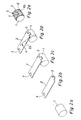
- the monolith 1 and 2 is intended to be a cylindrical monolith 1 wrapped with a bearing mat 2 on its outside become.
- the monolith 1 has a circular or elliptical or oval cross section. Are basically for the monolith 1 any cross-sections possible, so that the Monolith 1 can also have a cuboid shape.
- the monolith 1 can be made in a conventional manner from a ceramic Material.
- the bearing mat 2 is so in the present embodiment dimensioned that it is wrapped around the monolith 1 exactly once can be, i.e. the winding takes place through 360 °.
- the bearing mat 2 can be produced in the usual way and consist in particular of several layers.
- On her one End of the mat 2 has a tab 3, which is complementary to one formed at the other end of the bearing mat 2 Recess 4 is shaped. Due to the selected dimensioning the bearing mat 2 have their ends at their end faces a wrapping of the monolith 1 flush with each other by 360 ° to the system, in which case the tab 3 positively into the Recess 4 engages. This is particularly the case in FIGS. 1e recognizable in Fig. 2e.
- a Fasteners 5 used by a wrap mechanical element is formed.
- the fastener 5 by a band 6a formed in the present case as a self-adhesive tape 6a is formed.
- a self-adhesive tape 6a is formed.
- the fastener 5 in the embodiment according to FIG. 2 by a thread or formed by a cord 6b. This thread 6b can also be used With the help of an appropriate adhesive layer or be self-adhesive.
- the method according to the invention works as follows:
- the monolith 1 according to FIGS. 1a and 2a is independent of the bearing mat 2 according to FIGS. 1b and 2b.
- the bearing mat 2 according to FIGS. 1c and 2c with one end on the outside of the monolith 1 hung up.
- a relative is sufficient slight overlap of the adhesive tape 6a over each other abutting ends of the bearing mat 2 to a sufficient To ensure fixation of the bearing mat 2 on the monolith 1.
- the thread 6b is used several times completely around the monolith 1 or around the wound on it Bearing mat 2 wound, the thread 6b at Winding a feed across the circumferential direction, i.e. in Longitudinal direction of the monolith 1 experiences.
- This way 2e which is a secure fixation the storage mat 2 on the monolith 1 guaranteed.
- at a self-adhesive thread 6b are after completion of the winding no further fixation measures required.
- the free end of the thread 6b can, for example, with an adhesive strip on the outside of the bearing mat 2 or by pulling the free thread end under the existing one Windings are fixed.
- the supply of the adhesive tape 6a and the supply of the thread 6b when winding is preferably done by a unit that Provides fasteners 5 as continuous material.
- a roll of adhesive tape 7 is shown symbolically, that forms such a unity. After winding up and after fixing the wound-up mat 2 the wound fastener 5 from the continuous material or separated from the unit (e.g. tape roll 7).
- the method according to the invention can be easily implemented and is particularly feasible manually.
- a special Advantage of the method can be seen in that the monoliths 1 wrapped with the bearing mat 2 independently can be produced by a catalyst in which such a wrapped monolith 1 is to be used.
- the adhesive tape used in the embodiment according to FIG. 1 6a is representative of basically any band-shaped Fasteners shown.
- the thread 6b shown in Fig. 2 representative of basically any linear fastener used.
- the adhesive tape 6a comes when fixing of the mat end placed on the monolith 1 large area, so with maximum effect on the tab 3 System to attach the mat end to the monolith 1.
- the adhesive tape 6a extends accordingly with the bearing mat 2 fixed according to FIG. 1e, only via one relatively small section of the storage mat 2.
- the thread 6b extends after several windings corresponding to Fig. 2e essentially over the entire Width of the storage mat 2.
Landscapes
- Chemical & Material Sciences (AREA)
- Engineering & Computer Science (AREA)
- Chemical Kinetics & Catalysis (AREA)
- Mechanical Engineering (AREA)
- Health & Medical Sciences (AREA)
- Toxicology (AREA)
- Combustion & Propulsion (AREA)
- General Engineering & Computer Science (AREA)
- Exhaust Gas After Treatment (AREA)
- Catalysts (AREA)
Abstract
Description
- Fig. 1a bis 1e
- einen Prozessablauf zur Erläuterung des erfindungsgemäßen Verfahrens bei einer ersten Ausführungsform und
- Fig. 2a bis 2e
- einen Prozessablauf wie in Fig. 1, jedoch bei einer zweiten Ausführungsform.
- 1
- Monolith
- 2
- Lagermatte
- 3
- Lasche
- 4
- Aufnahme
- 5
- Befestigungsmittel
- 6a
- Klebeband
- 6b
- Faden/Schnur
- 7
- Rolle
Claims (14)
- Verfahren zum Befestigen einer Lagermatte (2) auf der Außenseite eines Monolithen (1), insbesondere eines Katalysators,
bei dem ein Ende der Lagermatte (2) auf die Monolithaußenseite aufgelegt wird,
bei dem das auf die Monolithaußenseite aufgelegte Mattenende mit einem wickelfähigen, mechanischen Befestigungsmittel (5) an der Monolithaußenseite fixiert wird,
bei dem die Lagermatte (2) und das Befestigungsmittel (5) gleichsinnig um die Monolithaußenseite gewickelt werden, wobei das Befestigungsmittel (5) auf der Außenseite der Lagermatte (2) aufliegt,
bei dem das Befestigungsmittel (5) weiter als die Lagermatte (2) um die Monolitaußenseite gewickelt wird, derart, daß das fertiggewickelte Befestigungsmittel (5) die aufgewickelte Lagermatte (2) auf der Monolithaußenseite fixiert. - Verfahren nach Anspruch 1,
dadurch gekennzeichnet, daß das Umwickeln der Monolithaußenseite mit der Lagermatte (2) und dem Befestigungsmittel (5) gleichzeitig erfolgt. - Verfahren nach Anspruch 1 oder 2,
dadurch gekennzeichnet, daß das Befestigungsmittel (5) als Endlosmaterial bereitgestellt und erst nach dem Fixieren der aufgewickelten Lagermatte (2) vom Endlosmaterial getrennt wird. - Verfahren nach einem der Ansprüche 1 bis 3,
dadurch gekennzeichnet, daß das Befestigungsmittel (5) linienförmig oder bandförmig ausgebildet ist. - Verfahren nach einem der Ansprüche 1 bis 4,
dadurch gekennzeichnet, daß das Befestigungsmittel (5) selbstklebend ausgebildet ist. - Verfahren nach einem der Ansprüche 1 bis 5,
dadurch gekennzeichnet, daß sich das Befestigungsmittel (5) nach dem Fixieren der Lagermatte (2) im wesentlichen über die gesamte, quer zur Umfangsrichtung des Monolithen (1) verlaufende Breite der Lagermatte (2) erstreckt. - Verfahren nach einem der Ansprüche 1 bis 6,
dadurch gekennzeichnet, daß die Lagermatte (2) an einem ihrer Enden eine Lasche (3) aufweist, die komplementär zu einer am anderen Ende ausgebildeten Ausnehmung (4) geformt ist, wobei die Mattenenden bei einer Umwicklung von 360° bündig aneinander anschließen, wobei die Lasche (3) die Ausnehmung (4) ausfüllt, wobei das Befestigungsmittel (5) bandförmig ausgebildet ist, wobei quer zur Umfangsrichtung des Monolithen (1) die Breite des Befestigungsbandes (6a) etwa gleich ist wie die Breite der Lasche (3). - Verfahren nach Anspruch 7,
dadurch gekennzeichnet, daß zum Fixieren des auf die Monolithaußenseite aufgelegten Mattenendes das Befestigungsband (6a) durch die Ausnehmung (4) oder über die Lasche (3) gelegt ist. - Mit einer Lagermatte (2) umwickelter Monolith (1), insbesondere für einen Katalysator, wobei die Lagermatte (2) mit einem wickelfähigen Befestigungsmittel (5) an der Monolithaußenseite befestigt ist, wobei ein Abschnitt des Befestigungsmittels (5) auf der Außenseite des Monolithen (1) und an der Innenseite der Lagermatte (2) anliegt, während das Befestigungsmittel (5) im übrigen auf der Außenseite der Lagermatte (2) aufliegt.
- Monolith nach Anspruch 9
dadurch gekennzeichnet, daß das Befestigungsmittel (5) linienförmig oder bandförmig ausgebildet ist. - Monolith nach Anspruch 9 oder 10,
dadurch gekennzeichnet, daß das Befestigungsmittel (5) selbstklebend ausgebildet ist. - Monolith nach einem der Ansprüche 9 bis 11,
dadurch gekennzeichnet, daß sich das Befestigungsmittel (5) im wesentlichen über die gesamte, quer zur Umfangsrichtung des Monolithen (1) verlaufende Breite der Lagermatte (2) erstreckt. - Monolith nach einem der Ansprüche 9 bis 12,
dadurch gekennzeichnet, daß die Lagermatte (2) an einem ihrer Enden eine Lasche (3) aufweist, die komplementär zu einer am anderen Ende ausgebildeten Ausnehmung (4) geformt ist, wobei die Mattenenden bei einer Umwicklung von 360° bündig aneinander anschließen, wobei die Lasche (3) die Aufnehmung (4) ausfüllt, wobei das Befestigungsmittel (5) bandförmig ausgebildet ist, wobei quer zur Umfangsrichtung des Monolithen (1) die Breite des Befestigungsbandes (6a) etwa gleich groß ist wie die Breite der Lasche (3). - Monolith nach Anspruch 13,
dadurch gekennzeichnet, daß das Befestigungsband (6a) durch die Ausnehmung (4) oder über die Lasche (3) gelegt ist.
Applications Claiming Priority (2)
| Application Number | Priority Date | Filing Date | Title |
|---|---|---|---|
| DE10057206 | 2000-11-17 | ||
| DE2000157206 DE10057206A1 (de) | 2000-11-17 | 2000-11-17 | Verfahren zum Befestigen einer Lagermatte auf einem Monolithen |
Publications (2)
| Publication Number | Publication Date |
|---|---|
| EP1207281A2 true EP1207281A2 (de) | 2002-05-22 |
| EP1207281A3 EP1207281A3 (de) | 2004-01-21 |
Family
ID=7663761
Family Applications (1)
| Application Number | Title | Priority Date | Filing Date |
|---|---|---|---|
| EP01124761A Withdrawn EP1207281A3 (de) | 2000-11-17 | 2001-10-17 | Verfahren zum Befestigen einer Lagermatte auf einem Monolithen |
Country Status (2)
| Country | Link |
|---|---|
| EP (1) | EP1207281A3 (de) |
| DE (1) | DE10057206A1 (de) |
Citations (2)
| Publication number | Priority date | Publication date | Assignee | Title |
|---|---|---|---|---|
| DE9404954U1 (de) | 1993-03-25 | 1994-07-28 | Minnesota Mining And Manufacturing Co., Saint Paul, Minn. | Katalysator |
| DE19803063A1 (de) | 1998-01-28 | 1999-07-29 | Eberspaecher J Gmbh & Co | Verfahren zur Halterung und Isolation von Keramikmonolithen in einer Kraftfahrzeug-Abgasanlage einschließlich hiernach gefertigte Lagerung |
Family Cites Families (4)
| Publication number | Priority date | Publication date | Assignee | Title |
|---|---|---|---|---|
| EP0299626B1 (de) * | 1987-06-18 | 1993-02-17 | Fibre Techniques Limited | Verfahren zum Schützen und Isolieren eines Katalysator-Blocks |
| GB9011849D0 (en) * | 1990-05-26 | 1990-07-18 | Fibre Tech Ltd | Catalytic converters |
| JP2855504B2 (ja) * | 1993-10-05 | 1999-02-10 | 本田技研工業株式会社 | 触媒コンバータ用保持材 |
| JP3370410B2 (ja) * | 1993-12-24 | 2003-01-27 | イビデン株式会社 | 自動車用排気ガス浄化用コンバーター断熱シール材の取付け方法 |
-
2000
- 2000-11-17 DE DE2000157206 patent/DE10057206A1/de not_active Withdrawn
-
2001
- 2001-10-17 EP EP01124761A patent/EP1207281A3/de not_active Withdrawn
Patent Citations (2)
| Publication number | Priority date | Publication date | Assignee | Title |
|---|---|---|---|---|
| DE9404954U1 (de) | 1993-03-25 | 1994-07-28 | Minnesota Mining And Manufacturing Co., Saint Paul, Minn. | Katalysator |
| DE19803063A1 (de) | 1998-01-28 | 1999-07-29 | Eberspaecher J Gmbh & Co | Verfahren zur Halterung und Isolation von Keramikmonolithen in einer Kraftfahrzeug-Abgasanlage einschließlich hiernach gefertigte Lagerung |
Also Published As
| Publication number | Publication date |
|---|---|
| EP1207281A3 (de) | 2004-01-21 |
| DE10057206A1 (de) | 2002-05-23 |
Similar Documents
| Publication | Publication Date | Title |
|---|---|---|
| DE3743723C1 (de) | Verfahren und Vorrichtung zur Herstellung eines Traegerkoerpers fuer einen katalytischen Reaktor | |
| EP0798178A1 (de) | Gurtaufroller | |
| DE4135695C2 (de) | Stab mit einer rohrförmigen Wandung aus Faserverbundwerkstoff und beidseitig angeordnetem Anschlußelement | |
| DE69315402T2 (de) | Verfahren zur Herstellung von Farbroller | |
| DE102007051976A1 (de) | Haspelvorrichtung und Verfahren zur Fixierung der Bunde bzw. Coils bei dieser Haspelvorrichtung | |
| DE1775881A1 (de) | Flexibler Schlauch | |
| DE3544439A1 (de) | Verfahren und vorrichtung zum herstellen von einzelkabeln mit optischen fasern oder komponenten von optischen faserkabeln fuer nachrichtenuebertragung | |
| DD287562A5 (de) | Auspuffschalldaempfer | |
| DE102019125865A1 (de) | Rollo, Verfahren zu dessen Erstellung und Rollosystem mit einem solchen Rollo | |
| DE60118421T2 (de) | Abgaskatalysator, Verfahren zu seiner Herstellung und Halte-und Dichtungsmaterial für Katalysatoren | |
| EP0277477A1 (de) | Metallischer Katalysator-Trägerkörper mit verkürztem Mantelrohr | |
| DE2100629C3 (de) | Verfahren zur Herstellung einer einlagigen Wicklung und Vorrichtung zur Durchführung des Verfahrens | |
| DE102004056804B4 (de) | Katalysator und/oder Partikelfilter sowie zugehöriges Herstellungsverfahren und zugehörige Lagermatte | |
| DE10205856B4 (de) | Lagerung eines Keramikmonolithen in einem Blechgehäuse z. B. bei Katalysatoren oder Partikelfiltern | |
| DE19739520C2 (de) | Vorrichtung zum Wickeln eines dünnen flachen Leiterdrahts in Hochkantstellung | |
| EP0381976B1 (de) | Heizelement | |
| DE10057206A1 (de) | Verfahren zum Befestigen einer Lagermatte auf einem Monolithen | |
| DE202009012185U1 (de) | Elektrisch beheizbare Medienleitung | |
| DE8204025U1 (de) | Schalldaempf-fuellung fuer einen auspufftopf | |
| DE69306988T2 (de) | Schnurwickelmechanismus | |
| DE19600812A1 (de) | Schutzanordnung mit zwei längsgeschlitzten Schutzrohren | |
| DE3625127C1 (en) | Pipe assembly comprising polymeric pipes | |
| DE7105454U (de) | Zugentlastung fuer isolierte anschlusslitzen | |
| DE102021123277A1 (de) | Wickelschlauch sowie Vorrichtung und Verfahren zur Herstellung eines Wickelschlauchs | |
| DE9114479U1 (de) | Schallgedämpftes Rohr |
Legal Events
| Date | Code | Title | Description |
|---|---|---|---|
| PUAI | Public reference made under article 153(3) epc to a published international application that has entered the european phase |
Free format text: ORIGINAL CODE: 0009012 |
|
| AX | Request for extension of the european patent |
Free format text: AL;LT;LV;MK;RO;SI |
|
| RAP1 | Party data changed (applicant data changed or rights of an application transferred) |
Owner name: J. EBERSPAECHER GMBH & CO. KG |
|
| PUAL | Search report despatched |
Free format text: ORIGINAL CODE: 0009013 |
|
| AK | Designated contracting states |
Kind code of ref document: A3 Designated state(s): AT BE CH CY DE DK ES FI FR GB GR IE IT LI LU MC NL PT SE TR |
|
| AX | Request for extension of the european patent |
Extension state: AL LT LV MK RO SI |
|
| AKX | Designation fees paid | ||
| REG | Reference to a national code |
Ref country code: DE Ref legal event code: 8566 |
|
| STAA | Information on the status of an ep patent application or granted ep patent |
Free format text: STATUS: THE APPLICATION IS DEEMED TO BE WITHDRAWN |
|
| 18D | Application deemed to be withdrawn |
Effective date: 20040722 |