EP1206987A1 - Anfahrstrang für eine Metall-Stranggiessvorrichtung, insbesondere für eine Vorprofil-Stahl-Stranggiessvorrichtung - Google Patents
Anfahrstrang für eine Metall-Stranggiessvorrichtung, insbesondere für eine Vorprofil-Stahl-Stranggiessvorrichtung Download PDFInfo
- Publication number
- EP1206987A1 EP1206987A1 EP01125587A EP01125587A EP1206987A1 EP 1206987 A1 EP1206987 A1 EP 1206987A1 EP 01125587 A EP01125587 A EP 01125587A EP 01125587 A EP01125587 A EP 01125587A EP 1206987 A1 EP1206987 A1 EP 1206987A1
- Authority
- EP
- European Patent Office
- Prior art keywords
- links
- line according
- starting
- continuous casting
- strand
- Prior art date
- Legal status (The legal status is an assumption and is not a legal conclusion. Google has not performed a legal analysis and makes no representation as to the accuracy of the status listed.)
- Granted
Links
- 229910000831 Steel Inorganic materials 0.000 title claims abstract description 22
- 239000010959 steel Substances 0.000 title claims abstract description 22
- 238000009749 continuous casting Methods 0.000 title claims description 10
- 239000002184 metal Substances 0.000 title claims description 4
- 239000007858 starting material Substances 0.000 title 1
- 229910000639 Spring steel Inorganic materials 0.000 claims abstract description 14
- 230000007704 transition Effects 0.000 claims description 4
- 238000005452 bending Methods 0.000 description 4
- 238000005266 casting Methods 0.000 description 2
- 230000003247 decreasing effect Effects 0.000 description 1
- 230000002349 favourable effect Effects 0.000 description 1
- 210000003746 feather Anatomy 0.000 description 1
- 230000009916 joint effect Effects 0.000 description 1
- 238000004519 manufacturing process Methods 0.000 description 1
- 230000000284 resting effect Effects 0.000 description 1
- 230000003313 weakening effect Effects 0.000 description 1
- 239000013585 weight reducing agent Substances 0.000 description 1
Images
Classifications
-
- B—PERFORMING OPERATIONS; TRANSPORTING
- B22—CASTING; POWDER METALLURGY
- B22D—CASTING OF METALS; CASTING OF OTHER SUBSTANCES BY THE SAME PROCESSES OR DEVICES
- B22D11/00—Continuous casting of metals, i.e. casting in indefinite lengths
- B22D11/08—Accessories for starting the casting procedure
- B22D11/081—Starter bars
Definitions
- the invention relates to a starting strand for a metal continuous casting device, especially for a pre-profile steel continuous casting device, with at least one flexible steel band, by means of which the mold cross section can be closed and along its length to the end individual links via the flexible steel band are connected.
- Such a start-up line is known from WO 97/46343.
- the start-up line is designed for the casting of pre-profiles.
- the start-up line has a uniform one Transitional section made up of individual links leading to an H-section assembled and attached to the flexible steel band that forms the core of the starting line.
- the transition section is on a standard section detachably connected, which is also connected with a flexible steel band.
- the H cross section is made up of a large number of cover plates and side plates formed so that the manufacture is complex and assembly from one Variety of parts must be made.
- the starting line is also very weight-intensive. Another disadvantage is the reduced flexibility, so that in bow sections of the strand guide more power for transport must be used.
- the invention has for its object the articulation function of such a start-up line to improve, with less weight a reduced effort to achieve for transport and handling.
- the task is solved according to the invention in that the beginning for the mold cross-section consists of a one-piece head piece, the dimensions corresponds to the mold cross-section and that subsequent, Row widths spaced apart on both sides and parallel rows in the start-up strand extension direction forming, bendable members in each case by means of a series of flexible steel strips lying on top of one another are connected to one another. Thereby a more favorable joint effect is achieved by the steel band, as this is located on the inside of the arch and on the outside of the link chain. The bending work to be applied is thereby reduced. Another advantage forms the existing play-free joint guide. There is also the advantage that in the case of pre-profile continuous casting devices, the cross section of the two rows of links can connect to the cast profile and simply continue it.
- the restoring force when bending the steel strip and its resistance to bending can be supported by the flexible steel band is designed as a spring steel band.
- One embodiment consists in that in the head piece at least one transverse to Approach strand extending direction for connection with the warm strand is provided. This makes known pliers-like elements avoided for notching.
- each two transversely opposite links by means of cross-connecting links are attached.
- the advantage is a parallel guidance of the two rows of links and a stiffening of the entire driveline without the weight being remarkable to increase.
- a further training consists in the fact that the individual links to the opposite surfaces of the two rows bevelled downwards are. This allows the starting strand to be guided on its underside and / or on the cross-connecting links.
- the head piece and / or the individual links with inner cavities are provided for weight reduction.
- the weight saving is there without having to accept a weakening according to the Number of links very high.
- the spring steel strips on the a row forming links are screwed or riveted. Thereby assembly is simplified.
- the starting line can be used cheaply in such a way that the two rows of links with spring steel bands in width of an H profile of the hot strand are spaced.
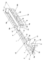
- the single figure shows a perspective view of the starting strand for the Longitudinal section of the continuous casting mold area
- the starting strand is used for a metal continuous casting device, in particular for a pre-profile steel continuous casting device and can also be used for slab strands, Block strands u. Like. Be used.
- the individual links 1 are with a flexible steel band 2 in the form of a spring steel band 2a with each other connected.
- the head 3 consists of a one-piece head piece 3a, which has the mold cross section (Pouring cross section) closes.
- the spring steel strip 2a begins at least on links 1a that have a reduced thickness.
- the between that Head piece 3a and the limbs 1 lying in reduced thickness 1a can also be articulated by means of bolts 4.
- the spring steel strip 2a begins on the links 1a with reduced thickness.
- the starting strand width is close 7 spaced, double-sided and parallel rows 8a and 8b in the start-up strand extension direction 9 extending, bendable in the arch links 1, which by means of in each case on a row 8a and 8b of flexible steel strip 2 resting with one another are connected.
- the flexible steel strip 2 is designed as a spring steel strip 2a.
- In the one-piece head piece 3a is at least one transverse to the direction of extension 9 extending recess 10 for connection to the Warm strand provided. Between the two rows 8a and 8b, which from the Links 1 exist, are at intervals in the starting strand extension direction 9, each two opposing links 1 by means of cross-connecting links 11 attached.
- Links 1a are designed as transition links 12 with a decreasing thickness. In order to be able to perform an arc movement in a vertical plane, grasp the links 1 which abut one another in a row 8a or 8b by means of a tongue 13 and a groove 14 in an articulated manner.
- the individual links 1 are on the opposite surfaces 15 in the both rows 8a and 8b each sloping downwards.
- the head piece 3a and / or the individual links 1 provided with internal cavities 16.
- the spring steel strips 2a are links forming the respective row 8a and 8b 1 screwed or riveted.
- Double- or H-profile strands are the two rows 8a and 8b made up of links 1 Spring steel strips 2a in the width of a double T or H profile the warm strand spaced.
Landscapes
- Engineering & Computer Science (AREA)
- Mechanical Engineering (AREA)
- Continuous Casting (AREA)
- Moulds For Moulding Plastics Or The Like (AREA)
- Ropes Or Cables (AREA)
- Treatment Of Steel In Its Molten State (AREA)
Abstract
Description
- 1
- Glieder
- 1 a
- Glieder mit reduzierter Dicke
- 2
- flexibles Stahlband
- 2a
- Federstahlband
- 3
- Kopf
- 3a
- einteiliges Kopfstück
- 4
- Bolzen
- 5
- Anfahrstrang-Anfang
- 6
- Kokillen-Querschnitt
- 7
- Anfahrstrangbreite
- 8a
- Reihe
- 8b
- Reihe
- 9
- Anfahrstrang-Erstreckungsrichtung
- 10
- Ausnehmung
- 11
- Quer-Verbindungsglieder
- 12
- Übergangsglieder
- 13
- Feder
- 14
- Nut
- 15
- Glieder-Fläche
- 16
- innere Hohlräume
- 17
- Außenkante
Claims (10)
- Anfahrstrang für eine Metall-Stranggießvorrichtung, insbesondere für eine Vorprofil- Stahl-Stranggießvorrichtung, mit zumindest einem flexiblen Stahlband, mittels dessen Kopf der Kokillen-Querschnitt verschließbar ist und auf dessen Länge bis zum Ende einzelne Glieder über das flexible Stahlband verbunden sind,
dadurch gekennzeichnet, dass der Anfang (5) für den Kokillen-Querschnitt (6) aus einem einteiligen Kopfstück (3a) besteht, das den Abmessungen des Kokillen-Querschnitts (6) entspricht und dass daran anschließende, auf Anfahrstrangbreite (7) beabstandete, beidseitig und parallele Reihen (8a; 8b) in Anfahrstrang-Erstreckungsrichtung (9) bildende, im Bogen biegefähige Glieder (1) mittels jeweils auf einer Reihe (8a; 8b) aufliegendem flexiblem Stahlband (2) miteinander verbunden sind. - Anfahrstrang nach Anspruch 1,
dadurch gekennzeichnet, dass das flexible Stahlband (2) als Federstahlband (2a) ausgeführt ist. - Anfahrstrang nach einem der Ansprüche 1 oder 2,
dadurch gekennzeichnet, dass in dem Kopfstück (3a) zumindest eine quer zur Anfahrstrang- Erstrekkungsrichtung (9) verlaufende Ausnehmung (10) zur Verbindung mit dem Warmstrang vorgesehen ist. - Anfahrstrang nach einem der Ansprüche 1 bis 3,
dadurch gekennzeichnet, dass zwischen den beiden Reihen (8a; 8b) aus Gliedern (1) in Abständen in Anfahrstrang-Erstreckungsrichtung (9) angeordnete , jeweils zwei sich quer gegenüberliegende Glieder (1) mittels Quer-Verbindungsglieder (11) befestigt sind. - Anfahrstrang nach einem der Ansprüche 1 bis 4,
dadurch gekennzeichnet, dass die auf das Kopfstück (3a) in Anfahrstrang-Erstreckungsrichtung (9) folgenden Glieder (1a) als Übergangsglieder (12) mit einer reduzierten Dikke ausgebildet sind. - Anfahrstrang nach einem der Ansprüche 1 bis 5,
dadurch gekennzeichnet, dass die in einer Reihe (8a; 8b) aneinander anliegenden Glieder (1) mittels Feder (13) und Nut (14) gelenkig schwenkbar ineinandergreifen. - Anfahrstrang nach einem der Ansprüche 1 bis 6,
dadurch gekennzeichnet, dass die einzelnen Glieder (1) an den sich gegenüberliegenden Flächen (15) der beiden Reihen (8a; 8b) nach unten zurücktretend angeschrägt sind. - Anfahrstrang nach einem der Ansprüche 1 bis 7,
dadurch gekennzeichnet, dass das Kopfstück (3a) und / oder die einzelnen Glieder (1) mit inneren Hohlräumen (16) zur Gewichtsverminderung versehen sind. - Anfahrstrang nach einem der Ansprüche 1 bis 8,
dadurch gekennzeichnet, dass die Federstahlbänder (2a) auf die jeweils eine Reihe (8a; 8b) bildenden Glieder (1) aufgeschraubt oder aufgenietet sind. - Anfahrstrang nach einem der Ansprüche 1 bis 9,
dadurch gekennzeichnet, dass die beiden Reihen (8a; 8b) aus Gliedern (1) mit aufgelegten Federstahlbändern (2a) in der Breite eines H-Profils des Warmstrangs beabstandet sind.
Applications Claiming Priority (2)
| Application Number | Priority Date | Filing Date | Title |
|---|---|---|---|
| DE10056911 | 2000-11-16 | ||
| DE10056911A DE10056911A1 (de) | 2000-11-16 | 2000-11-16 | Anfahrstrang für eine Metall-Stranggießvorrichtung, insbesondere für eine Vorprofil-Stahl-Stranggießvorrichtung |
Publications (2)
| Publication Number | Publication Date |
|---|---|
| EP1206987A1 true EP1206987A1 (de) | 2002-05-22 |
| EP1206987B1 EP1206987B1 (de) | 2005-08-31 |
Family
ID=7663585
Family Applications (1)
| Application Number | Title | Priority Date | Filing Date |
|---|---|---|---|
| EP01125587A Expired - Lifetime EP1206987B1 (de) | 2000-11-16 | 2001-10-26 | Anfahrstrang für eine Metall-Stranggiessvorrichtung, insbesondere für eine Vorprofil-Stahl-Stranggiessvorrichtung |
Country Status (5)
| Country | Link |
|---|---|
| US (1) | US6854508B2 (de) |
| EP (1) | EP1206987B1 (de) |
| AT (1) | ATE303215T1 (de) |
| DE (2) | DE10056911A1 (de) |
| ES (1) | ES2244542T3 (de) |
Citations (4)
| Publication number | Priority date | Publication date | Assignee | Title |
|---|---|---|---|---|
| FR1470202A (fr) * | 1966-02-28 | 1967-02-17 | Demag Ag | Bloc de démarrage à éléments articulés pour installations de coulée continue |
| FR1530416A (fr) * | 1963-07-10 | 1968-06-28 | Concast Ag | élément de lingot froid, pour installations de coulée continue |
| US5197533A (en) * | 1990-11-23 | 1993-03-30 | Gunther Behrends | Self-supporting, flexible continuous casting starter bar |
| WO1997046343A1 (en) * | 1996-06-06 | 1997-12-11 | Vantage One Design, Inc. | Beam blank starter bar |
Family Cites Families (3)
| Publication number | Priority date | Publication date | Assignee | Title |
|---|---|---|---|---|
| CH525049A (de) * | 1971-02-25 | 1972-07-15 | Concast Ag | Verfahren und Vorrichtung zum Einfahren des Anfahrstranges in eine Kokille beim Stranggiessen |
| AT348170B (de) * | 1977-03-25 | 1979-02-12 | Voest Ag | Anfahrstrang fuer stranggiessanlagen |
| JPS599261B2 (ja) * | 1979-12-03 | 1984-03-01 | 日立造船株式会社 | 連続鋳造設備におけるダミ−バ |
-
2000
- 2000-11-16 DE DE10056911A patent/DE10056911A1/de not_active Withdrawn
-
2001
- 2001-10-26 AT AT01125587T patent/ATE303215T1/de not_active IP Right Cessation
- 2001-10-26 EP EP01125587A patent/EP1206987B1/de not_active Expired - Lifetime
- 2001-10-26 ES ES01125587T patent/ES2244542T3/es not_active Expired - Lifetime
- 2001-10-26 DE DE50107268T patent/DE50107268D1/de not_active Expired - Lifetime
- 2001-11-15 US US10/003,032 patent/US6854508B2/en not_active Expired - Fee Related
Patent Citations (4)
| Publication number | Priority date | Publication date | Assignee | Title |
|---|---|---|---|---|
| FR1530416A (fr) * | 1963-07-10 | 1968-06-28 | Concast Ag | élément de lingot froid, pour installations de coulée continue |
| FR1470202A (fr) * | 1966-02-28 | 1967-02-17 | Demag Ag | Bloc de démarrage à éléments articulés pour installations de coulée continue |
| US5197533A (en) * | 1990-11-23 | 1993-03-30 | Gunther Behrends | Self-supporting, flexible continuous casting starter bar |
| WO1997046343A1 (en) * | 1996-06-06 | 1997-12-11 | Vantage One Design, Inc. | Beam blank starter bar |
Also Published As
| Publication number | Publication date |
|---|---|
| DE10056911A1 (de) | 2002-05-29 |
| US6854508B2 (en) | 2005-02-15 |
| ATE303215T1 (de) | 2005-09-15 |
| US20020084055A1 (en) | 2002-07-04 |
| DE50107268D1 (de) | 2005-10-06 |
| ES2244542T3 (es) | 2005-12-16 |
| EP1206987B1 (de) | 2005-08-31 |
Similar Documents
| Publication | Publication Date | Title |
|---|---|---|
| EP0593803A1 (de) | Vorrichtung zum Positionieren von Lasten | |
| DE2255283A1 (de) | Energiefuehrungskette | |
| EP2258566B1 (de) | Kettenglied für eine Gleitschutzkette | |
| EP1644595B1 (de) | Schalung mit einhakbarer spannschlossvorrichtung | |
| DE2157746C3 (de) | Presse zur Ausübung einer Flächenpressung | |
| DE4429348B4 (de) | Führungsschiene für eine Motorkettensäge | |
| DE4110668C1 (de) | ||
| EP3081462B1 (de) | Kettensteganordnung einer laufwerkskette einer pistenraupe, verfahren zur herstellung eines kettenstegprofils für eine derartige kettensteganordnung und laufwerkskette für eine pistenraupe | |
| DE102016111542B4 (de) | Schubkette mit standardisiertem Endstück | |
| EP1206987B1 (de) | Anfahrstrang für eine Metall-Stranggiessvorrichtung, insbesondere für eine Vorprofil-Stahl-Stranggiessvorrichtung | |
| EP1357257A2 (de) | Hebelartiger Nockenfolger aus Blech | |
| EP0566941B1 (de) | Hydraulische Druck- und Ziehvorrichtung, insbesondere für Eisenbahnschienen | |
| DE69704493T2 (de) | Positionierungsvorrichtung | |
| DE2853265C2 (de) | Anfahrstrang für Stranggießanlagen | |
| DE2854769C2 (de) | Aufhängevorrichtung für eine Einschienenhängebahn für den Berg- und Tunnelbau | |
| DE2066024B1 (de) | Biegewerkzeug zum Herstellen von Plattengliedern für Plattenbandförderer | |
| DE69107474T2 (de) | Selbsttragender, flexibler anfahrstrang für stranggiessanlage. | |
| DE10147846A1 (de) | Mitnehmer für Kettenkratzerförderer | |
| DE3200226C2 (de) | Verbolzung für Streckenausbaurahmen | |
| DE2150950C3 (de) | Kupplung fur Betonschalungselemente | |
| DE3320829C1 (de) | Umfangsnachgiebiger Ausbaubogen fuer Grubenstrecken,Tunnel oder dergleichen | |
| DE3305124C2 (de) | ||
| DE3024217C2 (de) | ||
| DE1675820C (de) | ||
| DE609074C (de) | Gleiskette fuer Fahrzeuge |
Legal Events
| Date | Code | Title | Description |
|---|---|---|---|
| PUAI | Public reference made under article 153(3) epc to a published international application that has entered the european phase |
Free format text: ORIGINAL CODE: 0009012 |
|
| 17P | Request for examination filed |
Effective date: 20011026 |
|
| AX | Request for extension of the european patent |
Free format text: AL;LT;LV;MK;RO;SI |
|
| AKX | Designation fees paid |
Designated state(s): AT BE CH CY DE DK ES FI FR GB GR IE IT LI LU MC NL PT SE TR |
|
| GRAP | Despatch of communication of intention to grant a patent |
Free format text: ORIGINAL CODE: EPIDOSNIGR1 |
|
| GRAS | Grant fee paid |
Free format text: ORIGINAL CODE: EPIDOSNIGR3 |
|
| GRAA | (expected) grant |
Free format text: ORIGINAL CODE: 0009210 |
|
| AK | Designated contracting states |
Kind code of ref document: B1 Designated state(s): AT BE CH CY DE DK ES FI FR GB GR IE IT LI LU MC NL PT SE TR |
|
| PG25 | Lapsed in a contracting state [announced via postgrant information from national office to epo] |
Ref country code: IE Free format text: LAPSE BECAUSE OF FAILURE TO SUBMIT A TRANSLATION OF THE DESCRIPTION OR TO PAY THE FEE WITHIN THE PRESCRIBED TIME-LIMIT Effective date: 20050831 Ref country code: FI Free format text: LAPSE BECAUSE OF FAILURE TO SUBMIT A TRANSLATION OF THE DESCRIPTION OR TO PAY THE FEE WITHIN THE PRESCRIBED TIME-LIMIT Effective date: 20050831 Ref country code: TR Free format text: LAPSE BECAUSE OF FAILURE TO SUBMIT A TRANSLATION OF THE DESCRIPTION OR TO PAY THE FEE WITHIN THE PRESCRIBED TIME-LIMIT Effective date: 20050831 Ref country code: NL Free format text: LAPSE BECAUSE OF FAILURE TO SUBMIT A TRANSLATION OF THE DESCRIPTION OR TO PAY THE FEE WITHIN THE PRESCRIBED TIME-LIMIT Effective date: 20050831 |
|
| REG | Reference to a national code |
Ref country code: CH Ref legal event code: EP Ref country code: GB Ref legal event code: FG4D Free format text: NOT ENGLISH |
|
| REG | Reference to a national code |
Ref country code: IE Ref legal event code: FG4D Free format text: LANGUAGE OF EP DOCUMENT: GERMAN |
|
| REF | Corresponds to: |
Ref document number: 50107268 Country of ref document: DE Date of ref document: 20051006 Kind code of ref document: P |
|
| PG25 | Lapsed in a contracting state [announced via postgrant information from national office to epo] |
Ref country code: AT Free format text: LAPSE BECAUSE OF NON-PAYMENT OF DUE FEES Effective date: 20051026 Ref country code: CY Free format text: LAPSE BECAUSE OF FAILURE TO SUBMIT A TRANSLATION OF THE DESCRIPTION OR TO PAY THE FEE WITHIN THE PRESCRIBED TIME-LIMIT Effective date: 20051026 |
|
| PG25 | Lapsed in a contracting state [announced via postgrant information from national office to epo] |
Ref country code: CH Free format text: LAPSE BECAUSE OF NON-PAYMENT OF DUE FEES Effective date: 20051031 Ref country code: BE Free format text: LAPSE BECAUSE OF NON-PAYMENT OF DUE FEES Effective date: 20051031 Ref country code: LI Free format text: LAPSE BECAUSE OF NON-PAYMENT OF DUE FEES Effective date: 20051031 Ref country code: LU Free format text: LAPSE BECAUSE OF NON-PAYMENT OF DUE FEES Effective date: 20051031 Ref country code: MC Free format text: LAPSE BECAUSE OF NON-PAYMENT OF DUE FEES Effective date: 20051031 |
|
| PG25 | Lapsed in a contracting state [announced via postgrant information from national office to epo] |
Ref country code: GR Free format text: LAPSE BECAUSE OF FAILURE TO SUBMIT A TRANSLATION OF THE DESCRIPTION OR TO PAY THE FEE WITHIN THE PRESCRIBED TIME-LIMIT Effective date: 20051130 Ref country code: DK Free format text: LAPSE BECAUSE OF FAILURE TO SUBMIT A TRANSLATION OF THE DESCRIPTION OR TO PAY THE FEE WITHIN THE PRESCRIBED TIME-LIMIT Effective date: 20051130 Ref country code: SE Free format text: LAPSE BECAUSE OF FAILURE TO SUBMIT A TRANSLATION OF THE DESCRIPTION OR TO PAY THE FEE WITHIN THE PRESCRIBED TIME-LIMIT Effective date: 20051130 |
|
| REG | Reference to a national code |
Ref country code: ES Ref legal event code: FG2A Ref document number: 2244542 Country of ref document: ES Kind code of ref document: T3 |
|
| GBT | Gb: translation of ep patent filed (gb section 77(6)(a)/1977) |
Effective date: 20051214 |
|
| PG25 | Lapsed in a contracting state [announced via postgrant information from national office to epo] |
Ref country code: PT Free format text: LAPSE BECAUSE OF FAILURE TO SUBMIT A TRANSLATION OF THE DESCRIPTION OR TO PAY THE FEE WITHIN THE PRESCRIBED TIME-LIMIT Effective date: 20060222 |
|
| NLV1 | Nl: lapsed or annulled due to failure to fulfill the requirements of art. 29p and 29m of the patents act | ||
| REG | Reference to a national code |
Ref country code: IE Ref legal event code: FD4D |
|
| REG | Reference to a national code |
Ref country code: CH Ref legal event code: PL |
|
| PLBE | No opposition filed within time limit |
Free format text: ORIGINAL CODE: 0009261 |
|
| STAA | Information on the status of an ep patent application or granted ep patent |
Free format text: STATUS: NO OPPOSITION FILED WITHIN TIME LIMIT |
|
| 26N | No opposition filed |
Effective date: 20060601 |
|
| EN | Fr: translation not filed | ||
| PG25 | Lapsed in a contracting state [announced via postgrant information from national office to epo] |
Ref country code: FR Free format text: LAPSE BECAUSE OF FAILURE TO SUBMIT A TRANSLATION OF THE DESCRIPTION OR TO PAY THE FEE WITHIN THE PRESCRIBED TIME-LIMIT Effective date: 20061027 |
|
| BERE | Be: lapsed |
Owner name: SMS DEMAG AG Effective date: 20051031 |
|
| PG25 | Lapsed in a contracting state [announced via postgrant information from national office to epo] |
Ref country code: FR Free format text: LAPSE BECAUSE OF FAILURE TO SUBMIT A TRANSLATION OF THE DESCRIPTION OR TO PAY THE FEE WITHIN THE PRESCRIBED TIME-LIMIT Effective date: 20051031 |
|
| PG25 | Lapsed in a contracting state [announced via postgrant information from national office to epo] |
Ref country code: FR Free format text: LAPSE BECAUSE OF FAILURE TO SUBMIT A TRANSLATION OF THE DESCRIPTION OR TO PAY THE FEE WITHIN THE PRESCRIBED TIME-LIMIT Effective date: 20050831 |
|
| PGFP | Annual fee paid to national office [announced via postgrant information from national office to epo] |
Ref country code: ES Payment date: 20110325 Year of fee payment: 10 Ref country code: GB Payment date: 20110323 Year of fee payment: 10 Ref country code: DE Payment date: 20110413 Year of fee payment: 10 |
|
| PGFP | Annual fee paid to national office [announced via postgrant information from national office to epo] |
Ref country code: IT Payment date: 20110331 Year of fee payment: 10 |
|
| GBPC | Gb: european patent ceased through non-payment of renewal fee |
Effective date: 20111026 |
|
| PG25 | Lapsed in a contracting state [announced via postgrant information from national office to epo] |
Ref country code: DE Free format text: LAPSE BECAUSE OF NON-PAYMENT OF DUE FEES Effective date: 20120501 |
|
| REG | Reference to a national code |
Ref country code: DE Ref legal event code: R119 Ref document number: 50107268 Country of ref document: DE Effective date: 20120501 |
|
| PG25 | Lapsed in a contracting state [announced via postgrant information from national office to epo] |
Ref country code: IT Free format text: LAPSE BECAUSE OF NON-PAYMENT OF DUE FEES Effective date: 20111026 Ref country code: GB Free format text: LAPSE BECAUSE OF NON-PAYMENT OF DUE FEES Effective date: 20111026 |
|
| REG | Reference to a national code |
Ref country code: ES Ref legal event code: FD2A Effective date: 20130607 |
|
| PG25 | Lapsed in a contracting state [announced via postgrant information from national office to epo] |
Ref country code: ES Free format text: LAPSE BECAUSE OF NON-PAYMENT OF DUE FEES Effective date: 20111027 |