EP1202601A2 - Schutzer für Lautsprechersmembran - Google Patents
Schutzer für Lautsprechersmembran Download PDFInfo
- Publication number
- EP1202601A2 EP1202601A2 EP01308886A EP01308886A EP1202601A2 EP 1202601 A2 EP1202601 A2 EP 1202601A2 EP 01308886 A EP01308886 A EP 01308886A EP 01308886 A EP01308886 A EP 01308886A EP 1202601 A2 EP1202601 A2 EP 1202601A2
- Authority
- EP
- European Patent Office
- Prior art keywords
- loudspeaker
- sheet
- protector
- frame
- mounting
- Prior art date
- Legal status (The legal status is an assumption and is not a legal conclusion. Google has not performed a legal analysis and makes no representation as to the accuracy of the status listed.)
- Withdrawn
Links
Images



Classifications
-
- H—ELECTRICITY
- H04—ELECTRIC COMMUNICATION TECHNIQUE
- H04R—LOUDSPEAKERS, MICROPHONES, GRAMOPHONE PICK-UPS OR LIKE ACOUSTIC ELECTROMECHANICAL TRANSDUCERS; ELECTRIC HEARING AIDS; PUBLIC ADDRESS SYSTEMS
- H04R1/00—Details of transducers, loudspeakers or microphones
- H04R1/02—Casings; Cabinets ; Supports therefor; Mountings therein
- H04R1/023—Screens for loudspeakers
Definitions
- the present invention relates to a protector for a loudspeaker cone.
- Loudspeaker cones are relatively fragile and easily damaged.
- a paper loudspeaker cone can be torn, punctured or creased by a single contact with a person's fingers or other object. Once a loudspeaker has been installed in a cabinet or other enclosure, it will be protected by its surrounds, including a mesh or grille through which sound is emitted by the loudspeaker.
- the invention provides a loudspeaker protector, comprising: a sheet of flexible material, the sheet being bounded by an edge; one or more mounting points on the sheet, each mounting point being adapted to receive a fixing member through the sheet and being positioned in a peripheral region of the sheet; and one or more lines of weakness in the sheet, the sheet being thereby adapted to tear or break preferentially along the lines of weakness; in which the lines of weakness separate the peripheral region at each mounting point from a central area of the sheet, so that the central area of the sheet may be torn from the peripheral region(s) after the or each mounting point has been held down by said fixing member(s).
- a loudspeaker comprising a frame, one or more mounting features by which the loudspeaker may be secured to an external object, a loudspeaker cone, and a loudspeaker protector, in which the cone is supported peripherally by the frame, the mounting features are provided on the frame beyond the periphery of the cone, the loudspeaker protector is affixed to the frame to protect the cone supported within the frame, and the loudspeaker protector has one or more mounting points in alignment with the mounting features of the frame, wherein the loudspeaker protector comprises: a sheet of flexible material, the sheet being bounded by an edge; one or more mounting points on the sheet, each mounting point being adapted to receive a fixing member through the sheet and being positioned in a peripheral region of the sheet; and one or more lines of weakness in the sheet, the sheet being thereby adapted to tear or break preferentially along the lines of weakness; in which the lines of weakness separate the peripheral region at each mounting point from a central area of the sheet, so that
- the mounting point in the loudspeaker protector is preferably an aperture, slit, dimple or other such feature formed or cut in the sheet material. If the mounting point is a hole through the sheet, then the sheet may include a sleeve that extends transversely away from the sheet around said hole.
- the loudspeaker frame will be a metallic frame.
- the mounting features of the frame can then be formed in the metal of the frame.
- the mounting points of the loudspeaker protector may then serve to insulate electrically the frame from the fixing members.
- each of the mounting features is an aperture in the frame, and the loudspeaker protector has a sleeve that extends into the aperture to insulate electrically the frame from the fixing member, which may be a metallic screw, bolt, press-fit stud or rivet.
- Figure 1 shows a prior art loudspeaker protector 1, formed in a rigid moulded plastic material with a continuous oval rim 2 inside of which are a large number of perforations 4.
- the perforations 4 are circular and closely packed so that these form a grille through which sound emitted by a loudspeaker may pass.
- the loudspeaker protector 1 in use is permanently affixed to a conventional loudspeaker 30 by applying glue (not shown) between the rim 2 of the loudspeaker protector 1 and a similarly shaped rim 39 of a pressed steel loudspeaker frame 40. Most of this glue is applied between matching flanges 12,14 of the loudspeaker protector 1 and loudspeaker frame 40, in areas surrounding four matching holes 6,8 in each of the rim 2 of the loudspeaker protector 1 and rim 39 of the loudspeaker frame 40.
- the holes 6,8 align so that a mounting screw or bolt 38 can be passed through each of the aligned pairs of holes 6,8 and into corresponding threaded bores 47 in an enclosure 75, such as a recess in a metallic motor vehicle door 80, to mount and secure the loudspeaker 30 to the enclosure 75.
- the loudspeaker protector 1 serves another purpose in this automotive application, by providing electrical insulation between the loudspeaker frame 30 and the four metal screws or bolts 38 used to secure the loudspeaker 30 to the metallic enclosure 75. This insulation is ensured by a cylindrical sleeve 16 that inserts fully into the loudspeaker frame clearance holes 8 when the loudspeaker protector 1 is affixed to the loudspeaker 30. This electrical insulation is important because it prevents electrical current from flowing from the metallic loudspeaker frame 40 to the metallic chassis of the vehicle through the connecting screw or bolt 38, in the event that an electrical fault develops within the loudspeaker 30. Because of this need for electrical insulation, the loudspeaker protector 1 must be permanently affixed to the loudspeaker frame 40.
- the loudspeaker protector 1 is moulded from a relatively expensive plastic material sold under the trade mark Noryl, which is a PPE-PS blend. This has high strength, and is suitable for use with adhesives that can affix this permanently to the metal loudspeaker frame 40.
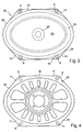
- FIG 2 shows a loudspeaker protector 25 according to the invention, when affixed to the loudspeaker 30 of Figure 3.
- the loudspeaker protector 25 comprises a sheet of flexible material 26, which is preferably 250 ⁇ m thick film, for example polyester film (PET) or polyether sulphone (PES), which has been cut and moulded into shape.
- the loudspeaker protector 25 has an edge 28 that generally conforms to the peripheral outline 29 of the loudspeaker 30, with the exception of a tab 32 that extends outwards from a rim area 34 of the protector 25.
- the loudspeaker protector 25 has four mounting points in the form of clearance holes 36 in the rim 34. When the protector 25 is affixed to the loudspeaker 30, these four clearance holes 36 align with the four holes 8 in the metallic frame 40 of the loudspeaker 30.
- Figure 5 shows a cross-sectional view through the loudspeaker protector 25 when affixed to the loudspeaker 30 by means of an adhesive 37 in the vicinity of the loudspeaker protector clearance holes 36. Also shown, is the metallic screw or bolt 38 passing through the hole 36 in the protector 25 and the matching clearance hole 8 in the loudspeaker metallic frame 40.
- the loudspeaker protector 25 has a cylindrical sleeve 42 that extends through the frame clearance hole 8 so that the metallic screw 38 cannot contact the metallic frame 40.
- a compressible hemispheric button 44 is also provided on an undersurface 54 of the flange 14 of the loudspeaker frame 40 to provide vibration isolation and electrical insulation between the frame 40 and a metallic support surface 46 to which the loudspeaker 30 is secured by the four screws or bolts 38.
- the loudspeaker 30 with loudspeaker protector 25 is first assembled to the supporting surface 46 with the loudspeaker protector 25 still protecting the loudspeaker cone 20.
- the loudspeaker protector 25 has semicircular perforations 50 that extend around each of the mounting points 36 of the protector 25, terminating at a peripheral edge 28 of the protector. The perforations therefore separate a central portion 52 of the protector 25 from four small portions 56 of sheet material 26 that extend around each of the four clearance holes 36.
- the perforations 50 form a line of weakness in the loudspeaker protector 25 so that a person may grip the projecting tab 32 and lift the protector 25 away from the loudspeaker 30 to cause the protector 25 to tear along each of the four perforations 50, and thereby remove the loudspeaker protector central portion 52 from the loudspeaker 30.
- the loudspeaker protector 25 is substantially removed from the loudspeaker 30, except for the four small portions 56 that remain adhered by the adhesive 37 and secured by the bolt 38 to the peripheral flanges 14 in the loudspeaker frame 40.
- the cylindrical insulating sleeves 42 therefore remain in place between the metallic screw 38 and loudspeaker frame 40.
- the pull-tab extends from a rim or peripheral region 34 of the sheet material forming the loudspeaker protector 52, but in such a way that this pull-tab 32 does not extend beyond rectangular bounds 60 defined by the long and short axes 62,64 of the oval loudspeaker cone 20.
- This arrangement facilitates packaging of the assembled loudspeaker 30 and protector 25, e.g. inside a matching rectangular cardboard shipping box (not shown).
- the pull-tab 32 therefore extends in a direction that lies between the major axis 62 and minor axis 64 of the oval loudspeaker 30.
- the central area 52 of the loudspeaker protector 25 is provided with a series of parallel corrugations 66 which have a rectangular channel cross-section as shown in Figure 5.
- the corrugations 66 extend in a direction transverse to a pull direction 68 of the pull-tab 32.
- the corrugations 66 therefore permit the central area 52 to curl and roll in the pull direction 68 as the pull-tab 32 is used to remove the central area 52 of the loudspeaker protector 25 from the loudspeaker 30.
- the corrugations 66 therefore provide stiffening in a direction normal to the plane of Figure 2, while still permitting easy removal of the central area 52 of the protector 25 after the loudspeaker 30 has been installed in its enclosure 75.
- the loudspeaker central area 52 has a colour noticeably different from that of the loudspeaker cone 20.
- loudspeaker cones 20 are black, and so at least a portion of the central area 52 should be coloured with a colour other than black.
- these peripheral regions 56 of the loudspeaker protector 25 are coloured black.
- the central area 52 of the loudspeaker protector 25 is domed by a step 70 that rises from the peripheral rim 34 of the protector 25. This provides a clearance gap 72 between the rubber isolating ring 24 connecting the loudspeaker cone 20 to the loudspeaker frame 40.
- the loudspeaker protector 25 according to the invention is relatively cheap to manufacture in large volumes. Because the protector 25 is temporary, it does not need to be designed to let sound from the loudspeaker pass through the protector with minimum disturbance. There is also no need to design the protector 25 so that this does not rattle or vibrate when the loudspeaker is operational.
- the material of the loudspeaker protector 25 may also be recyclable, thereby providing additional cost savings and reduced environmental impact.
- a loudspeaker protector according to the invention therefore provides an economical solution to the problem of how to provide protection to the fragile parts of a loudspeaker between the manufacture of the loudspeaker and installation in an enclosure.
Landscapes
- Physics & Mathematics (AREA)
- Engineering & Computer Science (AREA)
- Acoustics & Sound (AREA)
- Signal Processing (AREA)
- Details Of Audible-Bandwidth Transducers (AREA)
- Fittings On The Vehicle Exterior For Carrying Loads, And Devices For Holding Or Mounting Articles (AREA)
Applications Claiming Priority (2)
| Application Number | Priority Date | Filing Date | Title |
|---|---|---|---|
| GB0026265A GB2368485A (en) | 2000-10-27 | 2000-10-27 | Loudspeaker cone protector |
| GB0026265 | 2000-10-27 |
Publications (1)
| Publication Number | Publication Date |
|---|---|
| EP1202601A2 true EP1202601A2 (de) | 2002-05-02 |
Family
ID=9902042
Family Applications (1)
| Application Number | Title | Priority Date | Filing Date |
|---|---|---|---|
| EP01308886A Withdrawn EP1202601A2 (de) | 2000-10-27 | 2001-10-19 | Schutzer für Lautsprechersmembran |
Country Status (3)
| Country | Link |
|---|---|
| US (1) | US6651772B1 (de) |
| EP (1) | EP1202601A2 (de) |
| GB (1) | GB2368485A (de) |
Families Citing this family (5)
| Publication number | Priority date | Publication date | Assignee | Title |
|---|---|---|---|---|
| JP4594127B2 (ja) * | 2005-02-17 | 2010-12-08 | パイオニア株式会社 | スピーカー装置用のフレーム及びスピーカー装置 |
| JP2006229517A (ja) * | 2005-02-17 | 2006-08-31 | Pioneer Electronic Corp | スピーカー装置用のフレーム及びスピーカー装置 |
| CN101304622A (zh) * | 2007-05-09 | 2008-11-12 | 富准精密工业(深圳)有限公司 | 电声装置的音膜结构及其制备方法 |
| US20170155987A1 (en) * | 2015-11-03 | 2017-06-01 | Thomas & Darden, Inc. | Speaker enclosure having enhanced acoustic properties |
| JP7484546B2 (ja) * | 2020-08-07 | 2024-05-16 | ヤマハ株式会社 | ヘッドホン |
Family Cites Families (7)
| Publication number | Priority date | Publication date | Assignee | Title |
|---|---|---|---|---|
| US4281224A (en) * | 1980-04-21 | 1981-07-28 | Sparkomatic Corporation | Grille covered speaker assembly construction for compact automobiles and the like |
| JPH02260799A (ja) * | 1989-03-30 | 1990-10-23 | Pioneer Electron Corp | スピーカおよびその製造方法 |
| US4919227A (en) * | 1989-06-08 | 1990-04-24 | Oits Elevator Company | Tamper resistant speaker grille for intercom module |
| US4974698A (en) * | 1989-10-11 | 1990-12-04 | Oakwood Metal Fabricating Company | Speaker cover grille installation |
| JPH07107582A (ja) * | 1993-09-30 | 1995-04-21 | Tohoku Pioneer Kk | 車載用スピーカ |
| GB2305064A (en) * | 1995-09-09 | 1997-03-26 | Rover Group | Loudspeaker grille mounting arrangement |
| USD473213S1 (en) * | 2002-01-02 | 2003-04-15 | Audiobahn, Inc. | Speaker grill |
-
2000
- 2000-10-27 GB GB0026265A patent/GB2368485A/en not_active Withdrawn
-
2001
- 2001-10-19 EP EP01308886A patent/EP1202601A2/de not_active Withdrawn
- 2001-10-25 US US10/056,677 patent/US6651772B1/en not_active Expired - Fee Related
Also Published As
| Publication number | Publication date |
|---|---|
| GB0026265D0 (en) | 2000-12-13 |
| US6651772B1 (en) | 2003-11-25 |
| GB2368485A (en) | 2002-05-01 |
Similar Documents
| Publication | Publication Date | Title |
|---|---|---|
| US5085461A (en) | Air bag mount device for steering wheel including control switches | |
| EP1759935A1 (de) | Airbagvorrichtung und Verkleidungselement dafür | |
| US6651772B1 (en) | Loudspeaker cone protector | |
| US20080013780A1 (en) | Speaker device | |
| JP2002064917A (ja) | コルゲート管の補助部材 | |
| US11142159B2 (en) | Cover apparatus of driver airbag | |
| JP3797561B2 (ja) | スピーカ装置 | |
| JP2007181015A (ja) | スピーカブラケット及びスピーカ装置 | |
| JPH0872623A (ja) | 車両用スピーカの取付構造 | |
| CN211471277U (zh) | 一种电子产品防护膜 | |
| CN115950458A (zh) | 检测装置以及方向盘 | |
| JP3028941U (ja) | ホーンスイッチを内蔵したエアバッグモジュール | |
| JP2898924B2 (ja) | エアバッグドアのインサートとエアバッグドアを一体に有するインストルメントパネル | |
| JP3260080B2 (ja) | スピーカ | |
| CN222665753U (zh) | 一种车载触摸屏的保护膜及其料带 | |
| JP3362550B2 (ja) | エアバッグ装置のパッド | |
| US11477578B1 (en) | Speaker basket with splash shield | |
| JPH0113496Y2 (de) | ||
| JP4177000B2 (ja) | 電力用変圧器のブッシング保護カバー及びブッシング保護方法 | |
| JPH11321516A (ja) | ステアリングホイール | |
| JP3455876B2 (ja) | スピーカ | |
| KR100535513B1 (ko) | 사이드 가니쉬 장착 구조 | |
| JP5029437B2 (ja) | 車両用側突検出装置及びそれを利用した車両用乗員保護システム | |
| JPH069320U (ja) | 電線保護具 | |
| JP2003011743A (ja) | 車体パネル貫通穴へのワイヤハーネス配索構造 |
Legal Events
| Date | Code | Title | Description |
|---|---|---|---|
| PUAI | Public reference made under article 153(3) epc to a published international application that has entered the european phase |
Free format text: ORIGINAL CODE: 0009012 |
|
| AK | Designated contracting states |
Kind code of ref document: A2 Designated state(s): AT BE CH CY DE DK ES FI FR GB GR IE IT LI LU MC NL PT SE TR |
|
| AX | Request for extension of the european patent |
Free format text: AL;LT;LV;MK;RO;SI |
|
| STAA | Information on the status of an ep patent application or granted ep patent |
Free format text: STATUS: THE APPLICATION IS DEEMED TO BE WITHDRAWN |
|
| 18D | Application deemed to be withdrawn |
Effective date: 20031101 |