EP1202258A1 - Dispositif de commande de focalisation, support d'enregistrement et disque optique reproduisant le dispositif - Google Patents
Dispositif de commande de focalisation, support d'enregistrement et disque optique reproduisant le dispositif Download PDFInfo
- Publication number
- EP1202258A1 EP1202258A1 EP01908303A EP01908303A EP1202258A1 EP 1202258 A1 EP1202258 A1 EP 1202258A1 EP 01908303 A EP01908303 A EP 01908303A EP 01908303 A EP01908303 A EP 01908303A EP 1202258 A1 EP1202258 A1 EP 1202258A1
- Authority
- EP
- European Patent Office
- Prior art keywords
- signal
- object lens
- focus error
- error signal
- optical disk
- Prior art date
- Legal status (The legal status is an assumption and is not a legal conclusion. Google has not performed a legal analysis and makes no representation as to the accuracy of the status listed.)
- Granted
Links
Images


Classifications
-
- G—PHYSICS
- G11—INFORMATION STORAGE
- G11B—INFORMATION STORAGE BASED ON RELATIVE MOVEMENT BETWEEN RECORD CARRIER AND TRANSDUCER
- G11B7/00—Recording or reproducing by optical means, e.g. recording using a thermal beam of optical radiation by modifying optical properties or the physical structure, reproducing using an optical beam at lower power by sensing optical properties; Record carriers therefor
- G11B7/08—Disposition or mounting of heads or light sources relatively to record carriers
- G11B7/085—Disposition or mounting of heads or light sources relatively to record carriers with provision for moving the light beam into, or out of, its operative position or across tracks, otherwise than during the transducing operation, e.g. for adjustment or preliminary positioning or track change or selection
- G11B7/08505—Methods for track change, selection or preliminary positioning by moving the head
- G11B7/08511—Methods for track change, selection or preliminary positioning by moving the head with focus pull-in only
-
- G—PHYSICS
- G11—INFORMATION STORAGE
- G11B—INFORMATION STORAGE BASED ON RELATIVE MOVEMENT BETWEEN RECORD CARRIER AND TRANSDUCER
- G11B7/00—Recording or reproducing by optical means, e.g. recording using a thermal beam of optical radiation by modifying optical properties or the physical structure, reproducing using an optical beam at lower power by sensing optical properties; Record carriers therefor
- G11B7/08—Disposition or mounting of heads or light sources relatively to record carriers
- G11B7/09—Disposition or mounting of heads or light sources relatively to record carriers with provision for moving the light beam or focus plane for the purpose of maintaining alignment of the light beam relative to the record carrier during transducing operation, e.g. to compensate for surface irregularities of the latter or for track following
- G11B7/0908—Disposition or mounting of heads or light sources relatively to record carriers with provision for moving the light beam or focus plane for the purpose of maintaining alignment of the light beam relative to the record carrier during transducing operation, e.g. to compensate for surface irregularities of the latter or for track following for focusing only
- G11B7/0917—Focus-error methods other than those covered by G11B7/0909 - G11B7/0916
-
- G—PHYSICS
- G11—INFORMATION STORAGE
- G11B—INFORMATION STORAGE BASED ON RELATIVE MOVEMENT BETWEEN RECORD CARRIER AND TRANSDUCER
- G11B7/00—Recording or reproducing by optical means, e.g. recording using a thermal beam of optical radiation by modifying optical properties or the physical structure, reproducing using an optical beam at lower power by sensing optical properties; Record carriers therefor
- G11B7/12—Heads, e.g. forming of the optical beam spot or modulation of the optical beam
- G11B7/135—Means for guiding the beam from the source to the record carrier or from the record carrier to the detector
- G11B7/1372—Lenses
- G11B7/1374—Objective lenses
-
- G—PHYSICS
- G11—INFORMATION STORAGE
- G11B—INFORMATION STORAGE BASED ON RELATIVE MOVEMENT BETWEEN RECORD CARRIER AND TRANSDUCER
- G11B7/00—Recording or reproducing by optical means, e.g. recording using a thermal beam of optical radiation by modifying optical properties or the physical structure, reproducing using an optical beam at lower power by sensing optical properties; Record carriers therefor
- G11B2007/0003—Recording, reproducing or erasing systems characterised by the structure or type of the carrier
- G11B2007/0009—Recording, reproducing or erasing systems characterised by the structure or type of the carrier for carriers having data stored in three dimensions, e.g. volume storage
- G11B2007/0013—Recording, reproducing or erasing systems characterised by the structure or type of the carrier for carriers having data stored in three dimensions, e.g. volume storage for carriers having multiple discrete layers
-
- G—PHYSICS
- G11—INFORMATION STORAGE
- G11B—INFORMATION STORAGE BASED ON RELATIVE MOVEMENT BETWEEN RECORD CARRIER AND TRANSDUCER
- G11B2220/00—Record carriers by type
- G11B2220/20—Disc-shaped record carriers
- G11B2220/25—Disc-shaped record carriers characterised in that the disc is based on a specific recording technology
- G11B2220/2537—Optical discs
Definitions
- the present invention relates to a playback apparatus for a multilayer-recording optical disk. More particularly, it relates to layer jump control technology wherein an object lens is moved in its focusing direction in order to perform a focusing servo operation for any desired recording layer.
- an optical disk called “DVD” has come into practical use as a recording medium of large storage capacity.
- the DVD has at most two recording layers per side, and data can be recorded on both the sides thereof.
- the function of controlling the movement of an object lens in the focusing direction thereof (“layer jump function") is required of a playback apparatus for such a multilayer-recording optical disk in order that, when the playback of one recording layer (simply termed “layer” below) has been requested in a state where a focusing servo operation is proceeding for the other layer under playback, a focusing servo operation may be performed for the desired layer.
- a multilayer-recording optical disk playback apparatus in the prior art incarnates the above function by processing as stated below.
- Fig. 12 is a flow chart of a layer jump process in the case where, during the playback of the lower layer of an optical disk which includes the two recording layers of the lower layer (layer nearer to the object lens, and termed 'layer 0") and an upper layer (termed "layer 1"), the playback of the upper layer has been requested.
- Fig. 13 is a timing chart showing the relationship among a focus error signal, control signals, etc. on this occasion. Referring to Fig. 13, FcH and FcL comparator slice levels are reference voltages with which the focus error signal is compared and whose values are set at the shipment of the playback apparatus beforehand.
- the FcH signal assumes a Hi (high) output during a time period for which the voltage of the focus error signal exceeds the FcH comparator slice level (the voltage goes Hi), whereas it assumes a Lo (low) output during any other time period.
- the FcL signal assumes the Hi output during a time period for which the voltage of the focus error signal exceeds the FcL comparator slice level (the voltage goes Lo), whereas it assumes the Lo output during any other time period.
- a coil portion is disposed around an object lens which condenses a laser beam on the recording layer of the optical disk, and they are supported by a spring so as to be ascendible and descendible.
- a kick voltage is applied to the coil, a force is exerted in the direction of bringing the object lens near to the optical disk.
- a brake voltage is applied, a force is exerted in the direction of bringing the object lens away from the optical disk.
- the playback apparatus turns OFF a focusing servo (S401), whereupon it applies the kick voltage in the direction in which the object lens ascends (that is, in which the object lens comes near to the optical disk) (S402, time a in Fig. 13). Thereafter, it monitors a course from the rise of the pulse FcL (time b in Fig. 13) till the fall thereof (time c in Fig. 13) (S403). Upon detecting the fall of the pulse FcL, it terminates the application of the kick voltage (S404).
- the FcH and FcL comparator slice levels have the preset constant values. Therefore, the layer jump function cannot cope with discrepancy in the error levels of individual optical disks or playback apparatuses, or changes in the characteristics of the playback apparatus attributed to ambient conditions such as temperature. Moreover, since the comparator slice levels need to be confined within the peak levels of the focus error signal reliably in any playback state, they cannot be set at very large values. Therefore, in case of the occurrence of a focus error phenomenon called "stray light" wherein a small peak different from the essential peaks of the focus error signal appears in the vicinity of the reference level thereof, the layer jump might end in failure due to the misrecognition of a peak point, depending upon the values of the comparator slice levels.
- An object of the invention is to provide a layer jump technique of high stability which can cope with discrepancy in the error levels of individual optical disks or playback apparatuses, and changes in the characteristics of the playback apparatus attributed to ambient conditions such as temperature.
- a focusing control device is characterized by comprising an object lens which condenses a light beam on an optical disk constructed of a plurality of signal recording layers; focusing drive means for moving said object lens in a direction orthogonal to the recording layers of the optical disk; photodetection means for detecting light reflected from said optical disk; focus error signal generation means for generating a focus error signal which corresponds to defocusing of said object lens relative to any of said recording layers of said optical disk, on the basis of a detection signal of said photodetection means; peak detection means for detecting peaks of the focus error signal; reference value calculation means for calculating reference values of said focus error signal in accordance with detection signals of said peak detection means; comparison signal generation means for comparing said focus error signal with its reference values, and generating comparison signals based on results of the comparisons; and control means for accepting a request for moving a focusing position of said object lens, and generating and outputting signals which control said focusing drive means, on the basis of the detection
- Fig. 1 is a block diagram showing the focusing control mechanism of a multilayer-recording optical disk playback system.
- an optical disk 11 having a multilayer-recording structure for example, DVD is driven to rotate at a predetermined speed by a spindle motor 12.
- a laser beam is projected from an optical pickup 13, and is condensed on the recording layer of the optical disk 11 by an object lens 13a.
- Light reflected from the recording layer is read by the optical pickup 13.
- Part of the read optical signal is converted into an electric signal, which is inputted to a focus error generation circuit 14.
- the focus error generation circuit 14 generates a focus error signal from the converted electric signal.
- the focus error signal can be generated, for example, in such a way that quadrantal photodetection elements are disposed in the light receiving portion of the optical pickup 13, and that the difference among the outputs of the upper, lower, right and left photodetection elements is amplified in accordance with an astigmatism method.
- the signal read by the optical pickup 13 is converted into an electric signal (RF signal), which is inputted to a playback circuit 50.
- the playback circuit 50 plays back audio data, video data, etc. on the basis of a digital signal recorded on the recording layer of the optical disk 11.
- the focus error signal generated by the focus error generation circuit 14 is inputted to a peak detection circuit 15, an FcH comparator 17, an FcL comparator 18 and a switch 20.
- the FcH comparator 17 outputs an FcH signal in a case where the focus error signal has exceeded an FcH comparator slice level.
- the FcL comparator 18 outputs an FcL signal in a case where the focus error signal has exceeded an FcL comparator slice level.
- the FcH and FcL comparator slice levels are reference voltages which are set by a comparator slice level setting circuit 16 in advance of the playback of the disk 11, and a setting method therefor will be explained later.
- the FcH signal and FcL signal respectively outputted by the comparators 17 and 18 are both inputted to a layer jump control circuit 19.
- the peak detection circuit 15 detects the peak point of the focus error signal and measures the peak voltage thereof, which is outputted to the comparator slice level setting circuit 16. During the optical disk playback, the circuit 15 detects the peak point of the focus error signal and outputs a detection signal to the layer jump control circuit 19.
- the comparator slice level setting circuit 16 sets the comparator slice levels every optical disk playback operation.
- the comparator slice levels are set as the two levels on Hi (high) and Lo (low) sides in accordance with the peak voltage of the focus error signal in the peak level detection process, and they are respectively compared with the focus error signal in the comparators 17 and 18 during the optical disk playback.
- the layer jump control circuit 19 performs the control of a layer jump process in the case where, in a state in which a focusing servo operation is proceeding for a certain recording layer, the playback of another recording layer has been requested during the playback of the optical disk 11. More specifically, when the playback of the other recording layer has been requested, the layer jump control circuit 19 actuates the switch 20 to turn OFF a focusing servo. Thereafter, the circuit 19 outputs a signal for driving the object lens 13a, to an addition circuit 22 while monitoring the signals of the comparators 17, 18 and the signal of the peak detection circuit 15. When the layer jump process has been completed in due course, the circuit 19 actuates the switch 20 to turn ON the focusing servo. Besides, the circuit 19 has the function of measuring a time period for which the signal is outputted, and the function of controlling the time period for which the signal is outputted.
- a focusing servo control circuit 21 is constituted by a bias adjustment circuit, a gain adjustment circuit, a phase compensation circuit, an amplification circuit, etc., and it executes a focusing servo process in which a control signal to be applied to a focusing drive coil is generated so that the inputted focus error signal may assume its reference level. That is, the focusing servo control circuit 21 executes a process in which the focused position of the laser beam is kept following up a signal recording surface against the so-called "surface oscillations" etc. of the optical disk 11 during the rotation thereof.
- the ON/OFF of the input of the focus error signal to the focusing servo control circuit 21 is controlled by turning ON/OFF the switch 20.
- the addition circuit 22 adds up the object lens 13a driving signals delivered from the focusing servo control circuit 21 and the layer jump control circuit 19, and outputs the resulting signal to a focusing control drive circuit 23.
- the focusing control drive circuit 23 generates a voltage for driving the object lens 13a as corresponds to the inputted control signal, and feeds the voltage to a two-axis actuator 24.
- the two-axis actuator 24 drives the object lens 13a of the optical pickup 13 to move in two directions; the focusing direction of the object lens 13a and the radial direction of the optical disk 11.
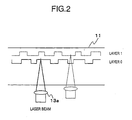
- the multilayer-recording optical disk 11 is constructed as a two-layer structure which has two recording layers as shown in Fig. 2.
- the layer near to the object lens 13a in the playback mode shall be called the "layer 0", and the layer remote therefrom the "layer 1".
- the recording layer indicated by a solid line is the layer 0
- the recording layer indicated by a broken line is the layer 1.
- the outside dimensions of the multilayer-recording optical disk 11 are, for example, a diameter of 120 mm and a thickness of 1.2 mm which are equal to those of a CD-ROM.
- the DVD however, has a structure in which two disks each being 0.6 mm thick are stuck together.
- Each side of the DVD has at most two recording layers, and data can be recorded on both the sides thereof.
- the storage capacities of the DVD are 4.7 Gbytes in case of recording on one layer of one side, 8.5 Gbytes in case of recording on the two layers of one side, 9.4 Gbytes in case of recording on one layer of each of both the sides, and 17 Gbytes in case of recording on the two layers of each of both the sides.
- the track pitch of the DVD is 0.74 ⁇ m, and the wavelength of a data reading laser employed for the playback system is 650 nm.
- the layer jump control according to the invention is applicable, not only to the optical disk of the two-layer structure, but also to an optical disk having a layer structure of at least three layers.
- the optical pickup 13 is constituted by the object lens 13a, a collimating lens 13b, a polarizing prism 13c, a semiconductor laser oscillator 13d, a cylindrical lens 13e and a photodetection element 13f.
- a laser beam emitted from the semiconductor laser oscillator 13d propagates rectilinearly through the polarizing prism 13c, and passes through the collimating lens 13b.
- the collimated laser beam is condensed on any recording layer of the optical disk 11 by the object lens 13a.
- Light reflected from the optical disk 11 retrogrades through the object lens 13a, and passes through the collimating lens 13b.
- the collimated light beam is orthogonally bent by the polarizing prism 13c, and the bent light beam falls on the photodetection element 13f through the cylindrical lens 13e.
- Fig. 4 is a sectional view showing a mechanism in which the object lens 13a is driven in its focusing direction by the two-axis actuator 24.
- the object lens 13a is supported by object lens supporting springs 24c through an object lens fixture 13g so as to be vertically and horizontallymovable.
- a focusing coil 24a is disposed around the object lens 13a, and a magnet 24b is further disposed outside the focusing coil 24a.
- the focusing coil 24a is fed with a control signal, the object lens 13a is given a driving force in its focusing direction as indicated by a double-headed arrow.
- Fig. 5 is a waveform diagram of the focus error signal in the case where the object lens 13a has moved from a position remote from the two-layer-recording optical disk 11, to a position near this optical disk 11.
- a 'layer 0" focusing point indicated by an arrow is the focusing position of the lower layer (layer 0)
- a "layer 1" focusing point is the focusing position of the upper layer (layer 1).
- the focus error levels of the "layer 0" focusing point and "layer 1" focusing point change depending upon optical characteristics, and they do not always agree.
- An upward direction and a downward direction shall be set as a Hi (high) direction and a Lo (low) direction with respect to the voltage 0 (zero) of the focus error signal.
- the focus error signal forms a peak in the Hi direction once, and it comes to the focusing point of the layer 0 in the vicinity of the reference level reached. Thereafter, the focus error signal forms a peak in the Lo direction, and it passes through the reference level again and forms a peak in the Hi direction. Further, the focus error signal comes to the focusing point of the layer 1 in the vicinity of the reference level subsequently reached.
- the focus error signal forms a peak in the Lo direction again.
- the processing is started (S101) in such a case where the optical disk 11 has been loaded, or where a power source has been turned ON in a loaded state. Then, the peak detection circuit 15 detects peak levels (S102). In this manner, the processing is executed every optical disk, whereby the layer jump process is permitted to cope with discrepancy in the characteristics of the optical disks, changes in the ambient conditions of the playback system, etc.
- the peak level detection process (S102) will be described by referring to the waveform diagram of Fig. 5 again and to a flow chart shown in Fig. 7.
- the object lens 13a is set at a position remote from the optical disk 11 (search- down, S201).
- the laser emission is turned ON (S202).
- the object lens 13a is gradually moved to a position near to the optical disk 11 (search-up, S203), and the change of the focus error signal is monitored.
- the focus error signal depicts a waveform shown in Fig. 5 as explained before. Peak points to be detected are the two points of the Lo peak point and Hi peak point indicated by arrows.
- the peak of the Hi side first detected is neglected in the peak level detection, and the voltage of the focus error signal relative to the reference level thereof at the Lo peak point first detected as the peak of the Lo side (S204) is set as a Lo peak level ScL (S205). Besides, the voltage of the focus error signal relative to the reference level thereof at the Hi peak point secondly detected as the peak of the Hi side (S206) is set as a Hi peak level ScH (S207). Thereafter, the object lens 13a is restored to its original position (S208), thereby to end the peak level detection process (S102).
- the comparator slice level setting circuit 16 sets the FcH comparator slice level and FcL comparator slice level being the reference voltages of the focus error level, on the basis of the values of the peak levels ScH and ScL by a method explained below (S103). More specifically, the FcH comparator slice level is set at a value which is obtained by multiplying the peak level ScH by a predetermined coefficient ⁇ , and the FcL comparator slice level at a value which is obtained by multiplying the peak level ScL by a predetermined coefficient ⁇ .
- the values of the coefficients ⁇ , ⁇ are positive values less than 1, for example, 0.2 or 0.5, and specified values are set as concrete numerical values in accordance with the characteristics of the optical disk playback apparatus beforehand.
- each of the coefficients ⁇ , ⁇ can also be set at values which differ between in case of shifting the layer 0 to the layer 1 and in case of shifting the layer 1 to the layer 0.
- the comparator slice levels are set every operation of inserting the disk, every operation of turning ON the power source and every operation of starting playback in a stopped state, the values thereof can cope with discrepancy in the error levels of the individual disks and changes in the ambient conditions. Especially, even when a small peak offset has appeared in the vicinity of the reference level on account of the stray light component of an optical system, no influence is exerted by presetting the values of the coefficients ⁇ , ⁇ so as to confine the peak offset within the comparator slice levels. Accordingly, the stability of the layer jump becomes very good.
- Fig. 8 is a flow chart for explaining the process on this occasion.
- Figs. 9 and 10 are timing charts in the case of the layer jump from the layer 0 to the layer 1.
- the lowermost stage represents the time.
- a time a corresponds to the initiation of the application of a kick voltage
- a time b the termination of the application of the kick voltage
- a time d the initiation of the application of a brake voltage
- a time e the termination of the application of the brake voltage and a time p the detection of a Hi peak.
- Fig. 9 illustrates a case where the time e of the brake voltage application termination is later than the time p of the Hi peak detection
- Fig. 10 illustrates a case where the time e of the brake voltage application termination is earlier than the time p of the Hi peak detection.
- the layer jump control circuit 19 changes-over the switch 20 to turn OFF a focusing servo (S301). Subsequently, the layer jump control circuit 19 sends a signal for generating the kick voltage in the direction in which the object lens 13a ascends (that is, in which the object lens 13a comes near to the optical disk 11), to the focusing drive circuit 23 through the addition circuit 22 (S302, time a in Fig. 9, time a in Fig. 10), and it initiates the measurement of a kick time period (S303).
- the layer jump control circuit 19 terminates the application of the kick voltage (S305), and it terminates the measurement of the kick time period (S306). Since the measured kick time period serves as the reference of a brake time period, it is held by the layer jump control circuit 19.
- the application of the kick voltage is terminated in accordance with the rise of the pulse FcL, so that the application time period of the kick voltage can be shortened.
- the kick voltage should desirably be higher.
- the reason therefor is that, when the kick voltage is higher, the application time period shortens still further, so the converging capability is enhanced more.
- the converging capability is higher, the layer jump can be quickened more, and playback which is a larger number of times faster can be realized.
- Figs. 11 (a) and (b) are schematic views for explaining the presence or absence of the influence of gravitation in the case where the playback apparatus 50 is of the horizontal type or vertical type.
- the gravitation acts on the object lens 13a in parallel with the focusing direction of this object lens, and hence, the apparatus 50 is influenced by the gravitation.
- the gravitation acts on the object lens 13a perpendicularly to the focusing direction of this object lens, and hence, the apparatus 50 is not influenced by the gravitation.
- the converging capability of the two-axis actuator 24 is heightened, a time period for which the horizontal type is influenced by the gravitation can be shortened. It is therefore possible to relieve the differences of the characteristics between the vertical type and the horizontal type attributed to the influence of the gravitation.
- the layer jump control circuit 19 begins to monitor the rise of the signal FcH (S307) through the peak detection circuit 15. Upon detecting the rise of the pulse FcH (time d in Fig. 9, time d in Fig. 10), the layer jump control circuit 19 sends a signal for generating the brake voltage in the direction in which the object lens 13a descends (that is, in which the object lens 13a comes away from the optical disk 11), to the focusing drive circuit 23 through the addition circuit 22 (S308), and it initiates the measurement of a brake time period (S309).
- the brake signal is kept sent until the brake time period equalizes to a value obtained in such a way that the kick time period measured before is multiplied by a coefficient ⁇ (S311).
- the coefficient ⁇ is one for adjusting the time lag of the control circuit 19 as to the setting of the brake time period relative to the kick time period, and it is set at the numerical value of, for example, 0.8 or 0.9.
- the coefficient ⁇ can also be set at values which are different between in the case of the jump from the layer 0 to the layer 1 and in the case of the jump from the layer 1 to the layer 0.
- the layer jump control circuit 19 terminates the application of the brake voltage (S312).
- the brake time period may well be set at a value obtained by subtracting the time lag of the control circuit 19 from the measured kick time period, instead of the value obtained by multiplying the kick time period by the coefficient ⁇ .
- the converging capability of the two-axis actuator 24 can be heightened.
- the peak detection circuit 15 is monitoring the Hi peak of the focus error signal (S310).
- the layer jump control circuit 19 judges whether or not the Hi peak point (time p in Fig. 9, time p in Fig. 10) has already been detected at the time of the brake voltage application termination (time e in Fig. 9, time e in Fig. 10).
- the focusing servo is turned ON (S314), and the playback of the layer 1 is started.
- the detection of the Hi peak point is waited for (S313), and the focusing servo is turned ON (S314) so as to start the playback of the layer 1 after the Hi peak point (time p in Fig. 9, time p in Fig. 10) has been detected.
- Such processing is based on the fact that a stable focusing servo operation is performed by turning ON the focusing servo after the Hi peak point has been passed. More specifically, when the focusing servo is turned ON immediately after the brake voltage application termination, an interval before the Hi peak point lies outside a focusing pull-in range, and hence, focusing might not be pulled in. In contrast, according to the processing, the focusing servo is turned ON after the Hi peak point without fail, so that the focusing can be reliably pulled in.
Applications Claiming Priority (5)
| Application Number | Priority Date | Filing Date | Title |
|---|---|---|---|
| JP2000059345 | 2000-03-03 | ||
| JP2000059345 | 2000-03-03 | ||
| JP2001053801 | 2001-02-28 | ||
| JP2001053801A JP2001319344A (ja) | 2000-03-03 | 2001-02-28 | フォーカス制御装置、記録媒体および光ディスク再生装置 |
| PCT/JP2001/001680 WO2001065551A1 (fr) | 2000-03-03 | 2001-03-05 | Dispositif de commande de focalisation, support d'enregistrement et disque optique reproduisant le dispositif |
Publications (3)
| Publication Number | Publication Date |
|---|---|
| EP1202258A1 true EP1202258A1 (fr) | 2002-05-02 |
| EP1202258A4 EP1202258A4 (fr) | 2006-04-19 |
| EP1202258B1 EP1202258B1 (fr) | 2007-06-27 |
Family
ID=26586765
Family Applications (1)
| Application Number | Title | Priority Date | Filing Date |
|---|---|---|---|
| EP01908303A Expired - Lifetime EP1202258B1 (fr) | 2000-03-03 | 2001-03-05 | Dispositif de commande de focalisation, support d'enregistrement et disque optique reproduisant le dispositif |
Country Status (13)
| Country | Link |
|---|---|
| US (1) | US6744709B2 (fr) |
| EP (1) | EP1202258B1 (fr) |
| JP (1) | JP2001319344A (fr) |
| KR (1) | KR100750797B1 (fr) |
| CN (1) | CN1165041C (fr) |
| AT (1) | ATE365961T1 (fr) |
| AU (1) | AU3608301A (fr) |
| BR (1) | BR0104782A (fr) |
| CA (1) | CA2370719A1 (fr) |
| DE (1) | DE60129089T2 (fr) |
| NZ (1) | NZ515835A (fr) |
| TW (1) | TW494402B (fr) |
| WO (1) | WO2001065551A1 (fr) |
Families Citing this family (17)
| Publication number | Priority date | Publication date | Assignee | Title |
|---|---|---|---|---|
| JP4089177B2 (ja) * | 2000-10-25 | 2008-05-28 | 株式会社日立製作所 | 光ディスク装置及び層間ジャンプ方法 |
| CN1191572C (zh) * | 2001-06-13 | 2005-03-02 | 建兴电子科技股份有限公司 | 光驱的峰值检测聚焦跳层方法 |
| WO2003036628A1 (fr) * | 2001-10-19 | 2003-05-01 | Sony Computer Entertainment Inc. | Procede d'identification de type de support de stockage |
| TW541518B (en) * | 2001-12-13 | 2003-07-11 | Acer Labs Inc | Method for controlling jump layer braking of CD drive |
| KR100425318B1 (ko) * | 2001-12-28 | 2004-03-31 | 삼성전자주식회사 | 광 매체의 레이어 절환 제어 방법 및 장치 |
| JP2004039125A (ja) * | 2002-07-04 | 2004-02-05 | Sony Corp | 光記録再生装置、焦点制御方法 |
| US7206987B2 (en) * | 2003-04-30 | 2007-04-17 | Hewlett-Packard Development Company, L.P. | Error detection and correction in a layered, 3-dimensional storage architecture |
| KR100520508B1 (ko) * | 2003-09-27 | 2005-10-11 | 삼성전자주식회사 | 포커스 인입 장치 및 방법 |
| KR100524996B1 (ko) * | 2003-12-30 | 2005-10-31 | 삼성전자주식회사 | 광 디스크 시스템의 엑츄에이터 코일 손상 방지 장치 및그 방법 |
| CN100447871C (zh) * | 2004-03-18 | 2008-12-31 | 联发科技股份有限公司 | 光驱跳轨结束时目标轨的循轨误差信号极性判断装置 |
| JP3992044B2 (ja) * | 2004-04-22 | 2007-10-17 | ソニー株式会社 | 再生装置、フォーカスジャンプ方法 |
| KR100706468B1 (ko) * | 2004-12-17 | 2007-04-10 | 주식회사 대우일렉트로닉스 | 홀로그래픽 롬 디스크의 기준광 포커스 서보 장치 |
| JP2006277777A (ja) | 2005-03-02 | 2006-10-12 | Sony Corp | 再生装置、レイヤジャンプ方法 |
| TWI360118B (en) * | 2006-11-14 | 2012-03-11 | Princeton Technology Corp | Device for layer jumping control of optical disc d |
| JP2010250901A (ja) * | 2009-04-16 | 2010-11-04 | Hitachi Ltd | 光ディスク装置及び多層ディスクに対するフォーカスジャンプ方法 |
| JP2011118959A (ja) * | 2009-11-30 | 2011-06-16 | Hitachi-Lg Data Storage Inc | 光ディスク装置 |
| CN105322341B (zh) * | 2015-07-02 | 2018-03-06 | 富士康(昆山)电脑接插件有限公司 | 电连接器及其制造方法 |
Citations (1)
| Publication number | Priority date | Publication date | Assignee | Title |
|---|---|---|---|---|
| US5999503A (en) * | 1995-09-07 | 1999-12-07 | Pioneer Electronic Corporation | Focus control apparatus in multi-layered disk reading apparatus utilizing acceleration, deceleration and focus error signals to switch between layers of the disk |
Family Cites Families (5)
| Publication number | Priority date | Publication date | Assignee | Title |
|---|---|---|---|---|
| JP3413684B2 (ja) * | 1994-12-16 | 2003-06-03 | ソニー株式会社 | 多層光ディスク再生装置および方法 |
| JP2000200431A (ja) | 1996-07-31 | 2000-07-18 | Sanyo Electric Co Ltd | フォーカスジャンプ方法 |
| JPH1139665A (ja) | 1997-07-15 | 1999-02-12 | Pioneer Electron Corp | 多層光記録媒体用フォーカス制御装置 |
| JP3758347B2 (ja) | 1997-12-25 | 2006-03-22 | 三菱電機株式会社 | 光ディスク装置におけるフォーカシング装置 |
| JP4092774B2 (ja) | 1998-05-07 | 2008-05-28 | 三菱電機株式会社 | 光ディスク装置におけるフォーカシング装置 |
-
2001
- 2001-02-28 JP JP2001053801A patent/JP2001319344A/ja active Pending
- 2001-03-02 US US09/798,799 patent/US6744709B2/en not_active Expired - Lifetime
- 2001-03-02 TW TW090104856A patent/TW494402B/zh not_active IP Right Cessation
- 2001-03-05 CN CNB018008917A patent/CN1165041C/zh not_active Expired - Lifetime
- 2001-03-05 KR KR1020017013880A patent/KR100750797B1/ko active IP Right Grant
- 2001-03-05 EP EP01908303A patent/EP1202258B1/fr not_active Expired - Lifetime
- 2001-03-05 NZ NZ515835A patent/NZ515835A/en not_active IP Right Cessation
- 2001-03-05 WO PCT/JP2001/001680 patent/WO2001065551A1/fr active IP Right Grant
- 2001-03-05 AT AT01908303T patent/ATE365961T1/de not_active IP Right Cessation
- 2001-03-05 DE DE60129089T patent/DE60129089T2/de not_active Expired - Lifetime
- 2001-03-05 AU AU36083/01A patent/AU3608301A/en not_active Abandoned
- 2001-03-05 CA CA002370719A patent/CA2370719A1/fr not_active Abandoned
- 2001-03-05 BR BR0104782-5A patent/BR0104782A/pt not_active Application Discontinuation
Patent Citations (1)
| Publication number | Priority date | Publication date | Assignee | Title |
|---|---|---|---|---|
| US5999503A (en) * | 1995-09-07 | 1999-12-07 | Pioneer Electronic Corporation | Focus control apparatus in multi-layered disk reading apparatus utilizing acceleration, deceleration and focus error signals to switch between layers of the disk |
Non-Patent Citations (1)
| Title |
|---|
| See also references of WO0165551A1 * |
Also Published As
| Publication number | Publication date |
|---|---|
| EP1202258B1 (fr) | 2007-06-27 |
| CA2370719A1 (fr) | 2001-09-07 |
| WO2001065551A1 (fr) | 2001-09-07 |
| CN1366661A (zh) | 2002-08-28 |
| EP1202258A4 (fr) | 2006-04-19 |
| NZ515835A (en) | 2003-09-26 |
| AU3608301A (en) | 2001-09-12 |
| CN1165041C (zh) | 2004-09-01 |
| ATE365961T1 (de) | 2007-07-15 |
| TW494402B (en) | 2002-07-11 |
| KR100750797B1 (ko) | 2007-08-20 |
| BR0104782A (pt) | 2002-05-14 |
| DE60129089T2 (de) | 2008-02-28 |
| DE60129089D1 (de) | 2007-08-09 |
| JP2001319344A (ja) | 2001-11-16 |
| US6744709B2 (en) | 2004-06-01 |
| KR20020012188A (ko) | 2002-02-15 |
| US20010024408A1 (en) | 2001-09-27 |
Similar Documents
| Publication | Publication Date | Title |
|---|---|---|
| EP1202258B1 (fr) | Dispositif de commande de focalisation, support d'enregistrement et disque optique reproduisant le dispositif | |
| JP4424256B2 (ja) | 光ディスク駆動装置、光ディスク装置及びその駆動方法 | |
| JP4377841B2 (ja) | フォーカス検出手段またはトラッキング検出手段の調整方法および光ディスク装置 | |
| US7145842B2 (en) | Objective lens moving control method and apparatus | |
| JP2002279654A (ja) | 光ディスク装置、対物レンズ移動制御方法 | |
| JPH05109085A (ja) | フオーカス制御装置 | |
| US7061835B2 (en) | Method and apparatus for focus control of lens for reading multilayer optical medium | |
| US7957233B2 (en) | Near-field gap pull-in method and optical disc apparatus therefor | |
| JP4525470B2 (ja) | 光ディスク駆動装置、光ディスク装置及びその駆動方法 | |
| JP4831928B2 (ja) | フォーカス制御装置、記録媒体および光ディスク再生装置 | |
| KR20060118617A (ko) | 개선된 레이어 점프에 의한 다층 광 디스크 판독/기록장치 | |
| MXPA01011127A (en) | Focus control device, recording medium and optical disk reproducing device | |
| JP4622697B2 (ja) | 光ディスク装置 | |
| KR100606671B1 (ko) | 광 기록재생기의 액츄에이터 진동 방지 방법 | |
| KR100214872B1 (ko) | 광픽업의 포커스 서보 제어방법 및 장치 | |
| JP3964279B2 (ja) | 光ディスク装置 | |
| JP3818143B2 (ja) | 光ディスク装置 | |
| US20070280063A1 (en) | Optical disk device performing high-speed seek operation and optical disk device seeking method | |
| JP2000187866A (ja) | 情報記録再生装置 | |
| JP2008108358A (ja) | 光ディスク再生装置、ビームエクスパンダー位置調整方法及びビームエクスパンダー位置調整プログラム | |
| JP2007035152A (ja) | 光ディスク装置および球面収差の補正方法 | |
| JP2007305252A (ja) | 光ディスク装置 |
Legal Events
| Date | Code | Title | Description |
|---|---|---|---|
| PUAI | Public reference made under article 153(3) epc to a published international application that has entered the european phase |
Free format text: ORIGINAL CODE: 0009012 |
|
| AK | Designated contracting states |
Kind code of ref document: A1 Designated state(s): AT BE CH CY DE DK ES FI FR GB GR IE IT LI LU MC NL PT SE TR |
|
| AX | Request for extension of the european patent |
Free format text: AL;LT;LV;MK;RO;SI |
|
| 17P | Request for examination filed |
Effective date: 20020305 |
|
| A4 | Supplementary search report drawn up and despatched |
Effective date: 20060303 |
|
| GRAP | Despatch of communication of intention to grant a patent |
Free format text: ORIGINAL CODE: EPIDOSNIGR1 |
|
| GRAS | Grant fee paid |
Free format text: ORIGINAL CODE: EPIDOSNIGR3 |
|
| GRAA | (expected) grant |
Free format text: ORIGINAL CODE: 0009210 |
|
| AK | Designated contracting states |
Kind code of ref document: B1 Designated state(s): AT BE CH CY DE DK ES FI FR GB GR IE IT LI LU MC NL PT SE TR |
|
| REG | Reference to a national code |
Ref country code: GB Ref legal event code: FG4D |
|
| REG | Reference to a national code |
Ref country code: CH Ref legal event code: EP |
|
| REG | Reference to a national code |
Ref country code: IE Ref legal event code: FG4D |
|
| REF | Corresponds to: |
Ref document number: 60129089 Country of ref document: DE Date of ref document: 20070809 Kind code of ref document: P |
|
| PG25 | Lapsed in a contracting state [announced via postgrant information from national office to epo] |
Ref country code: SE Free format text: LAPSE BECAUSE OF FAILURE TO SUBMIT A TRANSLATION OF THE DESCRIPTION OR TO PAY THE FEE WITHIN THE PRESCRIBED TIME-LIMIT Effective date: 20070927 |
|
| ET | Fr: translation filed | ||
| PG25 | Lapsed in a contracting state [announced via postgrant information from national office to epo] |
Ref country code: AT Free format text: LAPSE BECAUSE OF FAILURE TO SUBMIT A TRANSLATION OF THE DESCRIPTION OR TO PAY THE FEE WITHIN THE PRESCRIBED TIME-LIMIT Effective date: 20070627 |
|
| NLV1 | Nl: lapsed or annulled due to failure to fulfill the requirements of art. 29p and 29m of the patents act | ||
| REG | Reference to a national code |
Ref country code: CH Ref legal event code: PL |
|
| PG25 | Lapsed in a contracting state [announced via postgrant information from national office to epo] |
Ref country code: BE Free format text: LAPSE BECAUSE OF FAILURE TO SUBMIT A TRANSLATION OF THE DESCRIPTION OR TO PAY THE FEE WITHIN THE PRESCRIBED TIME-LIMIT Effective date: 20070627 |
|
| PG25 | Lapsed in a contracting state [announced via postgrant information from national office to epo] |
Ref country code: ES Free format text: LAPSE BECAUSE OF FAILURE TO SUBMIT A TRANSLATION OF THE DESCRIPTION OR TO PAY THE FEE WITHIN THE PRESCRIBED TIME-LIMIT Effective date: 20071008 Ref country code: PT Free format text: LAPSE BECAUSE OF FAILURE TO SUBMIT A TRANSLATION OF THE DESCRIPTION OR TO PAY THE FEE WITHIN THE PRESCRIBED TIME-LIMIT Effective date: 20071127 Ref country code: NL Free format text: LAPSE BECAUSE OF FAILURE TO SUBMIT A TRANSLATION OF THE DESCRIPTION OR TO PAY THE FEE WITHIN THE PRESCRIBED TIME-LIMIT Effective date: 20070627 |
|
| PG25 | Lapsed in a contracting state [announced via postgrant information from national office to epo] |
Ref country code: CH Free format text: LAPSE BECAUSE OF FAILURE TO SUBMIT A TRANSLATION OF THE DESCRIPTION OR TO PAY THE FEE WITHIN THE PRESCRIBED TIME-LIMIT Effective date: 20070627 Ref country code: LI Free format text: LAPSE BECAUSE OF FAILURE TO SUBMIT A TRANSLATION OF THE DESCRIPTION OR TO PAY THE FEE WITHIN THE PRESCRIBED TIME-LIMIT Effective date: 20070627 |
|
| PG25 | Lapsed in a contracting state [announced via postgrant information from national office to epo] |
Ref country code: GR Free format text: LAPSE BECAUSE OF FAILURE TO SUBMIT A TRANSLATION OF THE DESCRIPTION OR TO PAY THE FEE WITHIN THE PRESCRIBED TIME-LIMIT Effective date: 20070928 Ref country code: DK Free format text: LAPSE BECAUSE OF FAILURE TO SUBMIT A TRANSLATION OF THE DESCRIPTION OR TO PAY THE FEE WITHIN THE PRESCRIBED TIME-LIMIT Effective date: 20070627 Ref country code: IT Free format text: LAPSE BECAUSE OF FAILURE TO SUBMIT A TRANSLATION OF THE DESCRIPTION OR TO PAY THE FEE WITHIN THE PRESCRIBED TIME-LIMIT Effective date: 20070627 |
|
| PLBE | No opposition filed within time limit |
Free format text: ORIGINAL CODE: 0009261 |
|
| STAA | Information on the status of an ep patent application or granted ep patent |
Free format text: STATUS: NO OPPOSITION FILED WITHIN TIME LIMIT |
|
| 26N | No opposition filed |
Effective date: 20080328 |
|
| PG25 | Lapsed in a contracting state [announced via postgrant information from national office to epo] |
Ref country code: MC Free format text: LAPSE BECAUSE OF NON-PAYMENT OF DUE FEES Effective date: 20080331 |
|
| PG25 | Lapsed in a contracting state [announced via postgrant information from national office to epo] |
Ref country code: IE Free format text: LAPSE BECAUSE OF NON-PAYMENT OF DUE FEES Effective date: 20080305 |
|
| PG25 | Lapsed in a contracting state [announced via postgrant information from national office to epo] |
Ref country code: FI Free format text: LAPSE BECAUSE OF FAILURE TO SUBMIT A TRANSLATION OF THE DESCRIPTION OR TO PAY THE FEE WITHIN THE PRESCRIBED TIME-LIMIT Effective date: 20070627 |
|
| PG25 | Lapsed in a contracting state [announced via postgrant information from national office to epo] |
Ref country code: CY Free format text: LAPSE BECAUSE OF FAILURE TO SUBMIT A TRANSLATION OF THE DESCRIPTION OR TO PAY THE FEE WITHIN THE PRESCRIBED TIME-LIMIT Effective date: 20070627 |
|
| PG25 | Lapsed in a contracting state [announced via postgrant information from national office to epo] |
Ref country code: LU Free format text: LAPSE BECAUSE OF NON-PAYMENT OF DUE FEES Effective date: 20080305 |
|
| PG25 | Lapsed in a contracting state [announced via postgrant information from national office to epo] |
Ref country code: TR Free format text: LAPSE BECAUSE OF FAILURE TO SUBMIT A TRANSLATION OF THE DESCRIPTION OR TO PAY THE FEE WITHIN THE PRESCRIBED TIME-LIMIT Effective date: 20070627 |
|
| REG | Reference to a national code |
Ref country code: FR Ref legal event code: PLFP Year of fee payment: 16 |
|
| REG | Reference to a national code |
Ref country code: FR Ref legal event code: PLFP Year of fee payment: 17 |
|
| REG | Reference to a national code |
Ref country code: FR Ref legal event code: PLFP Year of fee payment: 18 |
|
| PGFP | Annual fee paid to national office [announced via postgrant information from national office to epo] |
Ref country code: DE Payment date: 20200218 Year of fee payment: 20 Ref country code: GB Payment date: 20200226 Year of fee payment: 20 |
|
| PGFP | Annual fee paid to national office [announced via postgrant information from national office to epo] |
Ref country code: FR Payment date: 20200214 Year of fee payment: 20 |
|
| REG | Reference to a national code |
Ref country code: DE Ref legal event code: R071 Ref document number: 60129089 Country of ref document: DE |
|
| REG | Reference to a national code |
Ref country code: GB Ref legal event code: PE20 Expiry date: 20210304 |
|
| PG25 | Lapsed in a contracting state [announced via postgrant information from national office to epo] |
Ref country code: GB Free format text: LAPSE BECAUSE OF EXPIRATION OF PROTECTION Effective date: 20210304 |