EP1201397B1 - Vorrichtung zur Herstellung eines unvulkanisierten Gummibandes - Google Patents
Vorrichtung zur Herstellung eines unvulkanisierten Gummibandes Download PDFInfo
- Publication number
- EP1201397B1 EP1201397B1 EP01308887A EP01308887A EP1201397B1 EP 1201397 B1 EP1201397 B1 EP 1201397B1 EP 01308887 A EP01308887 A EP 01308887A EP 01308887 A EP01308887 A EP 01308887A EP 1201397 B1 EP1201397 B1 EP 1201397B1
- Authority
- EP
- European Patent Office
- Prior art keywords
- screw
- passage
- unvulcanised rubber
- inlet
- thickness
- Prior art date
- Legal status (The legal status is an assumption and is not a legal conclusion. Google has not performed a legal analysis and makes no representation as to the accuracy of the status listed.)
- Expired - Lifetime
Links
- 230000001131 transforming effect Effects 0.000 claims description 24
- 230000007423 decrease Effects 0.000 claims description 10
- 230000003247 decreasing effect Effects 0.000 claims description 8
- 238000011144 upstream manufacturing Methods 0.000 description 4
- 238000004804 winding Methods 0.000 description 4
- 238000005096 rolling process Methods 0.000 description 2
- 150000001875 compounds Chemical class 0.000 description 1
- 230000001419 dependent effect Effects 0.000 description 1
- 238000010586 diagram Methods 0.000 description 1
- 238000004519 manufacturing process Methods 0.000 description 1
- 239000000463 material Substances 0.000 description 1
Images


Classifications
-
- B—PERFORMING OPERATIONS; TRANSPORTING
- B29—WORKING OF PLASTICS; WORKING OF SUBSTANCES IN A PLASTIC STATE IN GENERAL
- B29C—SHAPING OR JOINING OF PLASTICS; SHAPING OF MATERIAL IN A PLASTIC STATE, NOT OTHERWISE PROVIDED FOR; AFTER-TREATMENT OF THE SHAPED PRODUCTS, e.g. REPAIRING
- B29C48/00—Extrusion moulding, i.e. expressing the moulding material through a die or nozzle which imparts the desired form; Apparatus therefor
- B29C48/25—Component parts, details or accessories; Auxiliary operations
- B29C48/30—Extrusion nozzles or dies
- B29C48/305—Extrusion nozzles or dies having a wide opening, e.g. for forming sheets
- B29C48/31—Extrusion nozzles or dies having a wide opening, e.g. for forming sheets being adjustable, i.e. having adjustable exit sections
-
- B—PERFORMING OPERATIONS; TRANSPORTING
- B29—WORKING OF PLASTICS; WORKING OF SUBSTANCES IN A PLASTIC STATE IN GENERAL
- B29C—SHAPING OR JOINING OF PLASTICS; SHAPING OF MATERIAL IN A PLASTIC STATE, NOT OTHERWISE PROVIDED FOR; AFTER-TREATMENT OF THE SHAPED PRODUCTS, e.g. REPAIRING
- B29C48/00—Extrusion moulding, i.e. expressing the moulding material through a die or nozzle which imparts the desired form; Apparatus therefor
- B29C48/03—Extrusion moulding, i.e. expressing the moulding material through a die or nozzle which imparts the desired form; Apparatus therefor characterised by the shape of the extruded material at extrusion
- B29C48/07—Flat, e.g. panels
- B29C48/08—Flat, e.g. panels flexible, e.g. films
-
- B—PERFORMING OPERATIONS; TRANSPORTING
- B29—WORKING OF PLASTICS; WORKING OF SUBSTANCES IN A PLASTIC STATE IN GENERAL
- B29C—SHAPING OR JOINING OF PLASTICS; SHAPING OF MATERIAL IN A PLASTIC STATE, NOT OTHERWISE PROVIDED FOR; AFTER-TREATMENT OF THE SHAPED PRODUCTS, e.g. REPAIRING
- B29C48/00—Extrusion moulding, i.e. expressing the moulding material through a die or nozzle which imparts the desired form; Apparatus therefor
- B29C48/03—Extrusion moulding, i.e. expressing the moulding material through a die or nozzle which imparts the desired form; Apparatus therefor characterised by the shape of the extruded material at extrusion
- B29C48/12—Articles with an irregular circumference when viewed in cross-section, e.g. window profiles
-
- B—PERFORMING OPERATIONS; TRANSPORTING
- B29—WORKING OF PLASTICS; WORKING OF SUBSTANCES IN A PLASTIC STATE IN GENERAL
- B29C—SHAPING OR JOINING OF PLASTICS; SHAPING OF MATERIAL IN A PLASTIC STATE, NOT OTHERWISE PROVIDED FOR; AFTER-TREATMENT OF THE SHAPED PRODUCTS, e.g. REPAIRING
- B29C48/00—Extrusion moulding, i.e. expressing the moulding material through a die or nozzle which imparts the desired form; Apparatus therefor
- B29C48/25—Component parts, details or accessories; Auxiliary operations
- B29C48/255—Flow control means, e.g. valves
- B29C48/2556—Flow control means, e.g. valves provided in or in the proximity of dies
-
- B—PERFORMING OPERATIONS; TRANSPORTING
- B29—WORKING OF PLASTICS; WORKING OF SUBSTANCES IN A PLASTIC STATE IN GENERAL
- B29C—SHAPING OR JOINING OF PLASTICS; SHAPING OF MATERIAL IN A PLASTIC STATE, NOT OTHERWISE PROVIDED FOR; AFTER-TREATMENT OF THE SHAPED PRODUCTS, e.g. REPAIRING
- B29C48/00—Extrusion moulding, i.e. expressing the moulding material through a die or nozzle which imparts the desired form; Apparatus therefor
- B29C48/25—Component parts, details or accessories; Auxiliary operations
- B29C48/92—Measuring, controlling or regulating
-
- B—PERFORMING OPERATIONS; TRANSPORTING
- B29—WORKING OF PLASTICS; WORKING OF SUBSTANCES IN A PLASTIC STATE IN GENERAL
- B29C—SHAPING OR JOINING OF PLASTICS; SHAPING OF MATERIAL IN A PLASTIC STATE, NOT OTHERWISE PROVIDED FOR; AFTER-TREATMENT OF THE SHAPED PRODUCTS, e.g. REPAIRING
- B29C2948/00—Indexing scheme relating to extrusion moulding
- B29C2948/92—Measuring, controlling or regulating
- B29C2948/92504—Controlled parameter
- B29C2948/92609—Dimensions
- B29C2948/92628—Width or height
-
- B—PERFORMING OPERATIONS; TRANSPORTING
- B29—WORKING OF PLASTICS; WORKING OF SUBSTANCES IN A PLASTIC STATE IN GENERAL
- B29C—SHAPING OR JOINING OF PLASTICS; SHAPING OF MATERIAL IN A PLASTIC STATE, NOT OTHERWISE PROVIDED FOR; AFTER-TREATMENT OF THE SHAPED PRODUCTS, e.g. REPAIRING
- B29C2948/00—Indexing scheme relating to extrusion moulding
- B29C2948/92—Measuring, controlling or regulating
- B29C2948/92504—Controlled parameter
- B29C2948/92609—Dimensions
- B29C2948/92647—Thickness
-
- B—PERFORMING OPERATIONS; TRANSPORTING
- B29—WORKING OF PLASTICS; WORKING OF SUBSTANCES IN A PLASTIC STATE IN GENERAL
- B29C—SHAPING OR JOINING OF PLASTICS; SHAPING OF MATERIAL IN A PLASTIC STATE, NOT OTHERWISE PROVIDED FOR; AFTER-TREATMENT OF THE SHAPED PRODUCTS, e.g. REPAIRING
- B29C2948/00—Indexing scheme relating to extrusion moulding
- B29C2948/92—Measuring, controlling or regulating
- B29C2948/92504—Controlled parameter
- B29C2948/92809—Particular value claimed
-
- B—PERFORMING OPERATIONS; TRANSPORTING
- B29—WORKING OF PLASTICS; WORKING OF SUBSTANCES IN A PLASTIC STATE IN GENERAL
- B29C—SHAPING OR JOINING OF PLASTICS; SHAPING OF MATERIAL IN A PLASTIC STATE, NOT OTHERWISE PROVIDED FOR; AFTER-TREATMENT OF THE SHAPED PRODUCTS, e.g. REPAIRING
- B29C2948/00—Indexing scheme relating to extrusion moulding
- B29C2948/92—Measuring, controlling or regulating
- B29C2948/92819—Location or phase of control
- B29C2948/92857—Extrusion unit
- B29C2948/92904—Die; Nozzle zone
-
- B—PERFORMING OPERATIONS; TRANSPORTING
- B29—WORKING OF PLASTICS; WORKING OF SUBSTANCES IN A PLASTIC STATE IN GENERAL
- B29C—SHAPING OR JOINING OF PLASTICS; SHAPING OF MATERIAL IN A PLASTIC STATE, NOT OTHERWISE PROVIDED FOR; AFTER-TREATMENT OF THE SHAPED PRODUCTS, e.g. REPAIRING
- B29C2948/00—Indexing scheme relating to extrusion moulding
- B29C2948/92—Measuring, controlling or regulating
- B29C2948/92819—Location or phase of control
- B29C2948/92942—Moulded article
-
- B—PERFORMING OPERATIONS; TRANSPORTING
- B29—WORKING OF PLASTICS; WORKING OF SUBSTANCES IN A PLASTIC STATE IN GENERAL
- B29C—SHAPING OR JOINING OF PLASTICS; SHAPING OF MATERIAL IN A PLASTIC STATE, NOT OTHERWISE PROVIDED FOR; AFTER-TREATMENT OF THE SHAPED PRODUCTS, e.g. REPAIRING
- B29C2948/00—Indexing scheme relating to extrusion moulding
- B29C2948/92—Measuring, controlling or regulating
- B29C2948/92819—Location or phase of control
- B29C2948/92961—Auxiliary unit, e.g. for external melt filtering, re-combining or transfer between units
-
- B—PERFORMING OPERATIONS; TRANSPORTING
- B29—WORKING OF PLASTICS; WORKING OF SUBSTANCES IN A PLASTIC STATE IN GENERAL
- B29K—INDEXING SCHEME ASSOCIATED WITH SUBCLASSES B29B, B29C OR B29D, RELATING TO MOULDING MATERIALS OR TO MATERIALS FOR MOULDS, REINFORCEMENTS, FILLERS OR PREFORMED PARTS, e.g. INSERTS
- B29K2021/00—Use of unspecified rubbers as moulding material
Definitions
- the present invention relates to an apparatus for making a thin unvulcanised rubber tape having a thickness in a range of from 0.3 to 1.5 mm.
- unvulcanised rubber tyres are made of unvulcanised rubber components having various shapes and sizes.
- the unvulcanised rubber components are formed by extruders, the number and sizes of the extruders are dependent on the maximum size and the number of the kinds of the rubber components.
- at least several extruders which are relatively large-sized are required.
- the thickness of the unvulcanised rubber in itself can be easily decreased by rolling, but due to the elasticity and adhesiveness, it is difficult to stably obtain a constant thickness without breakage. Further, it is also difficult to obtain a constant width. As a result an additional work to cut the edges of the rolled rubber tape into the predetermined width is necessitated.
- an object of the present invention to provide an apparatus which can stably make an unvulcanised rubber tape with accuracy in width and thickness although the thickness is in a very small range of 0.3 to 1.5 mm.
- EP-A-1 033 236 discloses an apparatus according to the preamble of claim 1 (cf. col.3, lines 21-46; fig. 3 ).
- an apparatus for making an unvulcanised rubber tape comprises an extruder comprising a passage for unvulcanised rubber having an outlet for the extruded unvulcanised rubber, and a pair of calender rollers disposed near the outlet for adjusting the thickness of the extruded unvulcanised rubber passing therebetween, wherein the passage is made up of a transforming part having an inlet for the unvulcanised rubber at its upstream-side end, and a thinning part on the downstream side thereof defining the above-mentioned outlet at its downstream-side end, the transforming part gradually changes in the cross sectional shape from a circle to a flat shape, the thinning part has a flat cross sectional shape and gradually decreases in the thickness in the lower course of the passage, and a width W0 and a thickness T0 of the unvulcanised rubber tape, a width W1 of the inlet, a width WA and a thickness TA of the outlet, a length L of the transforming part, a width W2 of the
- apparatus 1 for making an unvulcanised rubber tape according to the present invention comprises an extruder 3 and a pair of calender rollers 19U and 19L.
- An unvulcanised rubber tape G to be made by the apparatus 1 has, as shown in Fig.6 , a predetermined finished thickness T0 in a range of from 0.3 to 1.5 mm, and a predetermined finished width W0 in a range of from 5 to 50 mm.
- the extruder 3 comprises a cylinder block 10 with a cylinder head 6, a worm screw 9 therein, an electric motor M for driving the worm screw 9, and a die 12 attached to the cylinder head 6.
- the cylinder block 10 is provided with a hole 10H in which the worm screw 9 is disposed.
- the hole 10H extends to the front end of the cylinder block 10 to open thereat, while keeping the same circular cross sectional shape.
- This opening 2 of the hole 10H is at a certain distance J from the front end of the worm screw 9 so as to form a rubber pool 17 therebetween.
- the rear end of the hole 10H is connected to an input port 10A for material rubber compound.
- the worm screw 9 is connected to the electric motor M through a reduction gear.
- the cylinder head 6 is fixed to the front end of the cylinder block 10 by means of bolts which penetrate through holes of a flange 10B formed at the front end of the cylinder block 10 and engage with threaded holes formed on the back face of the cylinder head 6.
- the cylinder head 6 is provided on the front face with a hollow part for mounting the die 12.
- the cylinder head 6 is provided with a hole 15 which extends from the rear end of the cylinder head 6 continuously from the hole 10H and opens at the rear end of the hollow part for mounting the die 12.
- the die 12 has a main portion put in the above-mentioned hollow part and a tip portion protruding therefrom.
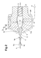
- the main portion has a shape to fit to that of the hollow part to engage each other as shown in Fig.2 .
- the cylinder head 6 can be split into at least two parts.
- the split face may be a plane positioned at the thickness centre of the hole 15.
- the die 12 has a hole 16 which extends from its rear end continuously from the hole 15 to its front end so as to open thereat defining an extruder outlet 5.
- the above-mentioned holes 15 and 16 form a passage 14 for the unvulcanised rubber.
- the sectional shape of the passage 14 gradually changes from a circle at the opening 2 to a flat shape at the extruder outlet 5, while gradually decreasing in sectional area S and height T in the thickness direction of the tape as shown in Fig.5 .
- the above-mentioned hole 15 comprises a transforming part 15A whose sectional shape changes continuously from the circle to a flat shape and a cylindrical part 15B whose sectional shape is a constant circle and which extends from the opening 2 to the transforming part 15A.
- the diameter of the cylindrical part 15B is the same as the opening 2.
- a pair of parallel sides having the same length continuously increase in length from the upstream end to the downstream end of the transforming part 15A, and these sides each form an inclined flat plane which is substantially triangular. Between the ends of the parallel sides, two curved sides of a circular arc extend. The radius of the circular arc decreases continuously from the upstream end to the downstream end of the transforming part 15A.
- the sectional shape already becomes a flat shape close to a flat rectangle rather than an oval due to its two parallel long straight sides.
- the degree of change in the sectional area S and the degree of change in the height T are reduced in comparison with those in the transforming part 15A so as to decrease a residual stress in the extruded unvulcanised rubber GP.
- the two parallel long straight sides continuously decrease in the length and as a result, these straight sides each form an inclined flat trapezoidal plane. Between the ends of the straight sides, curved sides of a small radius arc extend.
- the height T is decreased at a constant rate.
- the height T is decreased at a constant rate but smaller than that in the transforming part 15A. Similar to the height T, the sectional area S may be changed at a constant rate in each of the transforming part 15A and the hole 16. Thus, when only the passage 14 is considered, the border between the transforming part 15A and the hole 16 is regarded as a changing point of the rate of the decrease in the height T.
- the upper and lower calender rollers 19U and 19L are disposed to adjust the thickness and width of the unvulcanised rubber Gp extruded from the extruder outlet 5.
- the rollers 19U and 19L are supported by a frame 20 fixed to the cylinder head 6.
- the upper calender roller 19U and the lower calender roller 19L rotate at the same speed but in the opposite directions. It is important that the changes of the thickness and width by rolling are restricted to small values in order to stably make a very thin unvulcanised rubber tape with accuracy.
- the width W0 and thickness T0 of the finished unvulcanised rubber tape G, the width WA and height TA of the extruder outlet 5, the width W1 of the transforming part 15A at its upstream-side end, the width W2 of the transforming part 15A at its downstream-side end, the length L of the transforming part 15A along its central axis, and the pressure P in the passage 14 measured on the upstream side of the transforming part 15A satisfy the following relationships: W ⁇ 2 ⁇ W ⁇ 1 + 0.2 ⁇ XL WA ⁇ W ⁇ 2 0.7 ⁇ XW ⁇ 0 ⁇ WA ⁇ 1.0 ⁇ XW ⁇ 0 1.5 ⁇ XT ⁇ 0 ⁇ TA ⁇ 10.0 ⁇ XT ⁇ 0 P > 40 kgf / sq . cm 3.92 MPa
- width W2 is more than W1+0.2XL and/or the width WA is more than the width W2, then the flow of rubber to both side edges of the passage 14 becomes not enough and it becomes difficult to obtain the constant width WO.
- width WA is less than 0.7 times the width W0 of the finished rubber tape G, as the amount of the roll processing excessively increases, the dimensional accuracy especially accuracy in the width and quality of the finished rubber tape G deteriorate.
- the width WA is set in a range of from 0.8 to 0.9 times the width W0.
- the height TA is less than 1.5 times the thickness T0 of the finished rubber tape, then undulation is liable to occur on the rubber tape G causing unevenness in the thickness. If the height TA is more than 10 times the thickness T0, then the amount of the roll processing excessively increases and it becomes difficult to make the width stable.
- the thickness TA is in a range of from 3 to 5 times the thickness T0.
- the width of the extruded rubber Gp is varied by variation of the delivery pressure of the screw and as a result the width of the rolled tape is also varied.
- the pressure P is in a range of more than 60 kgf/sq.cm. (5.88 MPa).
- the widths W1 and W2 are 30 mm
- the length L is 26.5 mm
- the width WA is 18.0 mm
- the height TA is 3.0 mm
- the inner pressure P is 50 to 80 kgf/sq.cm (7.84 MPa)
- the diameters of the calender rollers are 80 mm.
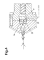
- Fig.4 shows a state of the extruder provided between the passage 14 and the worm screw 9 with a throttle 23 in order to stabilise the pressure P of the unvulcanised rubber flowing into the passage 14 from the worn screw 9.
- the throttle 23 is defined by the aperture of a throttle ring which is disposed in a circular groove 24 formed along the joint between the cylinder head 6 and the cylinder block 10.
- the diameter D1 of the aperture is set in a range of from 0.5 to 0.2 times the inside diameter D of the hole 10H.
- a ring whose inside diameter is the same as the passage 14 and rubber pool 17 is disposed in the groove.
- a pressure sensor 22 for the delivery pressure of the worm screw there is provided with a pressure sensor 22 for the delivery pressure of the worm screw.
- the output of the sensor 22 is given to a controller 21 for the electric motor M and the rotational speed thereof is controlled according to the delivery pressure so that the pressure becomes constant.
- the shape of the passage and the pressure are specifically defined. Therefore, the amount of the roll processing to the extruded rubber is decreased. Further, due to the increased pressure and the specific shape, influence of variation of the pressure on the extruded rubber such as variation of the thickness, width and residual stress can be decreased. Also the magnitude of the residual stress is decreased. As a result, it becomes possible to stably make a very thin unvulcanised rubber tape with accuracy in both width and thickness.
Landscapes
- Engineering & Computer Science (AREA)
- Mechanical Engineering (AREA)
- Manufacturing & Machinery (AREA)
- Extrusion Moulding Of Plastics Or The Like (AREA)
Claims (5)
- Vorrichtung zum Herstellen eines unvulkanisierten Kautschukbandes (G), das eine fertige Dicke T0 in einem Bereich von 0,3 bis 1,5 mm aufweist, umfassend einen Extruder (3) mit einem Durchgang (14) für unvulkanisierten Kautschuk, der einen Auslass (5) für den extrudierten unvulkanisierten Kautschuk definiert, und ein Paar Kalanderwalzen (19U, 19L), das nahe bei dem Auslass (5) angeordnet ist, um die Dicke des extrudierten unvulkanisierten Kautschuks, der dazwischen hindurchtritt, einzustellen,
dadurch gekennzeichnet, dass
der Durchgang (14) aus einem Umformungsteil (15A) besteht, der einen Einlass für den unvulkanisierten Kautschuk an seinem Ende auf der stromaufwärtigen Seite und einen Abdünnungsteil (16) an der stromabwärtigen Seite davon, der den Auslass an seinem Ende auf der stromabwärtigen Seite definiert, aufweist, wobei der Umformungsteil (15A) die Querschnittsform allmählich von einem Kreis zu einer flachen Form in dem unteren Verlauf des Durchgangs (14) verändert, wobei der Abdünnungsteil (16) eine flache Querschnittsform aufweist und seine Dicke in dem unteren Verlauf des Durchgangs allmählich abnimmt, wobei die Dicke T0 und eine Breite des unvulkanisierten Kautschukbandes WO, eine Breite W1 des Einlasses, eine Breite WA und eine Dicke TA des Auslasses, eine Länge L des Umformungsteils (15A), eine Breite W2 des Umformungsteils an seinem Ende auf der stromabwärtigen Seite und ein Druck P des unvulkanisierten Kautschuks, der in den Einlass einströmt, die folgenden Beziehungen erfüllen


- Vorrichtung nach Anspruch 1,
dadurch gekennzeichnet, dass
in dem Abdünnungsteil (16) die Dicke mit einer im Wesentlichen konstanten Rate abnimmt, und in dem Umformungsteil (15A) die Dicke mit einer Rate abnimmt, die größer als die im Wesentlichen konstante Rate ist. - Vorrichtung nach Anspruch 1,
dadurch gekennzeichnet, dass
der Extruder eine Schnecke (9) umfasst, um den unvulkanisierten Kautschuk in den Einlass des Durchgangs (14) zu drücken, und eine Drossel zwischen der Schnecke (9) und dem Einlass des Durchgangs (14) angeordnet ist. - Vorrichtung nach Anspruch 1,
dadurch gekennzeichnet, dass
der Extruder eine Schnecke (9) umfasst, um den unvulkanisierten Kautschuk in den Einlass des Durchgangs zu drücken, eine Drossel zwischen der Schnecke und dem Einlass des Durchgangs angeordnet ist, und einen Sensor für den Abgabedruck der Schnecke und einen Controller für einen Motor, der die Schnecke antreibt, der gemäß einem Ausgang des Sensors in der Lage ist, die Drehgeschwindigkeit der Schnecke derart zu steuern, dass der Abgabedruck über einem vorbestimmten Niveau gehalten wird. - Vorrichtung nach Anspruch 1,
dadurch gekennzeichnet, dass
der Extruder eine Schnecke (9), um den unvulkanisierten Kautschuk in den Einlass des Durchgangs (14) zu drücken, einen Sensor für den Druck des unvulkanisierten Kautschuks, der von der Schnecke in den Einlass einströmt, und einen Controller für einen Motor, der die Schnecke antreibt, umfasst, der gemäß einem Ausgang des Sensors in der Lage ist, die Drehgeschwindigkeit der Schnecke derart zu steuern, dass der Druck stabilisiert wird.
Applications Claiming Priority (2)
| Application Number | Priority Date | Filing Date | Title |
|---|---|---|---|
| JP2000322887A JP3621879B2 (ja) | 2000-10-23 | 2000-10-23 | ゴムストリップの製造装置 |
| JP2000322887 | 2000-10-23 |
Publications (3)
| Publication Number | Publication Date |
|---|---|
| EP1201397A2 EP1201397A2 (de) | 2002-05-02 |
| EP1201397A3 EP1201397A3 (de) | 2002-12-04 |
| EP1201397B1 true EP1201397B1 (de) | 2010-09-08 |
Family
ID=18800682
Family Applications (1)
| Application Number | Title | Priority Date | Filing Date |
|---|---|---|---|
| EP01308887A Expired - Lifetime EP1201397B1 (de) | 2000-10-23 | 2001-10-19 | Vorrichtung zur Herstellung eines unvulkanisierten Gummibandes |
Country Status (4)
| Country | Link |
|---|---|
| US (1) | US6688872B2 (de) |
| EP (1) | EP1201397B1 (de) |
| JP (1) | JP3621879B2 (de) |
| DE (1) | DE60143010D1 (de) |
Families Citing this family (14)
| Publication number | Priority date | Publication date | Assignee | Title |
|---|---|---|---|---|
| JP4721392B2 (ja) * | 2003-04-04 | 2011-07-13 | 株式会社ブリヂストン | ゴムシート製造装置 |
| JP4547136B2 (ja) * | 2003-07-16 | 2010-09-22 | 株式会社ブリヂストン | タイヤおよびタイヤの製造方法 |
| US20050092365A1 (en) * | 2003-10-28 | 2005-05-05 | Rawes Godfrey D. | Extrusion assembly |
| JP4426937B2 (ja) * | 2004-09-14 | 2010-03-03 | 住友ゴム工業株式会社 | ゴムストリップの製造装置 |
| JP5297711B2 (ja) * | 2008-07-18 | 2013-09-25 | 株式会社ブリヂストン | ゴム部材の成形装置及び成形方法 |
| EP2366527B1 (de) * | 2009-08-25 | 2016-02-17 | Sumitomo Rubber Industries, Ltd. | Kautschukextrusionsdüse |
| US20120318439A1 (en) * | 2009-12-22 | 2012-12-20 | Stefano Testi | Extrusion process and device for producing elastomeric compounds |
| CN102744858A (zh) * | 2011-12-29 | 2012-10-24 | 青岛宏达塑胶总公司 | 挤出板材外加式幅宽调节装置 |
| JP5735932B2 (ja) * | 2012-06-07 | 2015-06-17 | 住友ゴム工業株式会社 | ゴムストリップの製造方法及び製造装置 |
| FR3000423B1 (fr) * | 2012-12-27 | 2015-02-27 | Michelin & Cie | Methode et dispositif de regulation d'un dispositif d'extrusion |
| JP2016002712A (ja) * | 2014-06-17 | 2016-01-12 | 住友ゴム工業株式会社 | ゴム部材の製造装置及び製造方法 |
| ITUB20161171A1 (it) * | 2016-02-29 | 2017-08-29 | Flon Project S R L | Un dispositivo modellatore per ottenere un nastro o semilavorati di PTFE bi-orientato. |
| JP7198151B2 (ja) * | 2019-05-17 | 2022-12-28 | Toyo Tire株式会社 | 帯状ゴム部材の成形方法及び成形装置 |
| DE102022200817A1 (de) * | 2022-01-25 | 2023-07-27 | Continental Reifen Deutschland Gmbh | Vorrichtung und computerimplementiertes Verfahren zur Steuerung einer Extrusionsanlage, Extrusionsanlage und computerlesbares Speichermedium |
Family Cites Families (11)
| Publication number | Priority date | Publication date | Assignee | Title |
|---|---|---|---|---|
| DE2028064A1 (de) * | 1970-06-08 | 1971-12-16 | Troester Maschf Paul | Schneckenpresse zum Ausformen von vorplastifizierten Elastomeren oder Thermoplasten |
| US3890078A (en) * | 1972-01-31 | 1975-06-17 | Industrial Nucleonics Corp | Noninteracting extruder control |
| US3871810A (en) * | 1972-11-20 | 1975-03-18 | Uniroyal Inc | Extruder and roller-die combination |
| US4124346A (en) * | 1976-04-07 | 1978-11-07 | The Goodyear Tire & Rubber Company | Extruder die arrangement |
| JPS5418865A (en) * | 1977-07-14 | 1979-02-13 | Kobe Steel Ltd | Extrusion molding of synthetic resin and die therefor |
| SU1224161A1 (ru) * | 1984-08-02 | 1986-04-15 | Научно-исследовательский институт крупногабаритных шин | Щелева головка дл шприцевани ленты из высоков зкой резиновой смеси |
| US5179521A (en) * | 1989-03-29 | 1993-01-12 | Quantum Chemical Corporation | System and method for controlling continuous mixer with melt pump |
| FR2673141B1 (fr) | 1991-02-21 | 1994-09-02 | Aerospatiale | Filiere reglable a galets tournants pour production d'une bande a bords inclines. |
| US5221541A (en) * | 1991-09-11 | 1993-06-22 | Bridgestone/Firestone, Inc. | Extruder head for elastomeric material |
| US5176925A (en) * | 1992-03-25 | 1993-01-05 | Amphenol Corporation | Extrusion die with static mixer insert |
| JP3322648B2 (ja) | 1999-03-03 | 2002-09-09 | 住友ゴム工業株式会社 | ゴム搬送装置およびそれを用いたゴム成形装置 |
-
2000
- 2000-10-23 JP JP2000322887A patent/JP3621879B2/ja not_active Expired - Lifetime
-
2001
- 2001-10-12 US US09/974,859 patent/US6688872B2/en not_active Expired - Lifetime
- 2001-10-19 DE DE60143010T patent/DE60143010D1/de not_active Expired - Lifetime
- 2001-10-19 EP EP01308887A patent/EP1201397B1/de not_active Expired - Lifetime
Also Published As
| Publication number | Publication date |
|---|---|
| EP1201397A2 (de) | 2002-05-02 |
| EP1201397A3 (de) | 2002-12-04 |
| JP2002127234A (ja) | 2002-05-08 |
| US6688872B2 (en) | 2004-02-10 |
| DE60143010D1 (de) | 2010-10-21 |
| US20020048615A1 (en) | 2002-04-25 |
| JP3621879B2 (ja) | 2005-02-16 |
Similar Documents
| Publication | Publication Date | Title |
|---|---|---|
| EP1201397B1 (de) | Vorrichtung zur Herstellung eines unvulkanisierten Gummibandes | |
| EP2033763B1 (de) | Verfahren zur Herstellung eines dünnen Gummiteils, Gummiwalze und Verfahren zum Walzen von Gummi | |
| US9085104B2 (en) | Sculpted extrusion die | |
| KR102425279B1 (ko) | 연속 라벨 용지의 타발 스크랩 권취장치 및 타발 스크랩 권취방법 | |
| EP1555114B1 (de) | Reifenherstellungsverfahren, vorrichtung zum anpressen eines kautschukmantels zur durchführung des reifenherstellungsverfahrens und reifen | |
| CN111348474B (zh) | 连续标签纸张的去除废纸卷绕装置 | |
| CN101631666A (zh) | 用于制造橡胶条材料的装置 | |
| US11745404B2 (en) | Rubber strip manufacturing method and rubber strip manufacturing apparatus | |
| JP5041930B2 (ja) | 円環状ゴム部材の製造方法及びその製造装置 | |
| JP6644626B2 (ja) | ビードコア被覆方法及びビードコア被覆装置 | |
| EP1634690A2 (de) | Vorrichtung zur Herstellung eines Gummistreifens | |
| JPWO2009037736A1 (ja) | ゴムストリップ材の成形装置及びゴムストリップ材の成形方法 | |
| JP3522841B2 (ja) | 伸展加工した合成樹脂フイルムの搬送方法及びその装置 | |
| EP1568476B1 (de) | Verfahren zur herstellung einer kordverstärkten reifenkomponente | |
| US20250018634A1 (en) | Rubber member molding apparatus | |
| JP6882964B2 (ja) | ビードコア被覆方法及びビードコア被覆装置 | |
| EP1818165B1 (de) | Verfahren zum umwickeln einer formtrommel mit kautschukstreifenmaterial | |
| JP3983064B2 (ja) | ゴムシート成形装置 | |
| CN116394566B (zh) | 胎圈芯包覆装置 | |
| EP2633984A1 (de) | Formvorrichtung und formverfahren für eine reifenkomponente | |
| CN113260501A (zh) | 胎圈芯包覆方法及胎圈芯包覆装置 | |
| EP3501780B1 (de) | Verfahren und vorrichtung zur herstellung von gummibändern | |
| JP2002160309A (ja) | タイヤ補強方法並びにタイヤ補強マシン | |
| JPS63258358A (ja) | ロ−ラ |
Legal Events
| Date | Code | Title | Description |
|---|---|---|---|
| PUAI | Public reference made under article 153(3) epc to a published international application that has entered the european phase |
Free format text: ORIGINAL CODE: 0009012 |
|
| AK | Designated contracting states |
Kind code of ref document: A2 Designated state(s): AT BE CH CY DE DK ES FI FR GB GR IE IT LI LU MC NL PT SE TR |
|
| AX | Request for extension of the european patent |
Free format text: AL;LT;LV;MK;RO;SI |
|
| PUAL | Search report despatched |
Free format text: ORIGINAL CODE: 0009013 |
|
| AK | Designated contracting states |
Kind code of ref document: A3 Designated state(s): AT BE CH CY DE DK ES FI FR GB GR IE IT LI LU MC NL PT SE TR |
|
| AX | Request for extension of the european patent |
Free format text: AL;LT;LV;MK;RO;SI |
|
| 17P | Request for examination filed |
Effective date: 20030514 |
|
| AKX | Designation fees paid |
Designated state(s): DE FR GB IT |
|
| 17Q | First examination report despatched |
Effective date: 20061219 |
|
| GRAC | Information related to communication of intention to grant a patent modified |
Free format text: ORIGINAL CODE: EPIDOSCIGR1 |
|
| GRAP | Despatch of communication of intention to grant a patent |
Free format text: ORIGINAL CODE: EPIDOSNIGR1 |
|
| RIC1 | Information provided on ipc code assigned before grant |
Ipc: B29K 21/00 20060101ALI20100303BHEP Ipc: B29C 47/14 20060101AFI20100303BHEP |
|
| GRAS | Grant fee paid |
Free format text: ORIGINAL CODE: EPIDOSNIGR3 |
|
| GRAA | (expected) grant |
Free format text: ORIGINAL CODE: 0009210 |
|
| AK | Designated contracting states |
Kind code of ref document: B1 Designated state(s): DE FR GB IT |
|
| REG | Reference to a national code |
Ref country code: GB Ref legal event code: FG4D |
|
| REF | Corresponds to: |
Ref document number: 60143010 Country of ref document: DE Date of ref document: 20101021 Kind code of ref document: P |
|
| PLBI | Opposition filed |
Free format text: ORIGINAL CODE: 0009260 |
|
| PLAX | Notice of opposition and request to file observation + time limit sent |
Free format text: ORIGINAL CODE: EPIDOSNOBS2 |
|
| 26 | Opposition filed |
Opponent name: KRAUSSMAFFEI BERSTORFF GMBH Effective date: 20110608 |
|
| REG | Reference to a national code |
Ref country code: DE Ref legal event code: R026 Ref document number: 60143010 Country of ref document: DE Effective date: 20110608 |
|
| PLAF | Information modified related to communication of a notice of opposition and request to file observations + time limit |
Free format text: ORIGINAL CODE: EPIDOSCOBS2 |
|
| PLBB | Reply of patent proprietor to notice(s) of opposition received |
Free format text: ORIGINAL CODE: EPIDOSNOBS3 |
|
| PLCK | Communication despatched that opposition was rejected |
Free format text: ORIGINAL CODE: EPIDOSNREJ1 |
|
| APAH | Appeal reference modified |
Free format text: ORIGINAL CODE: EPIDOSCREFNO |
|
| APBM | Appeal reference recorded |
Free format text: ORIGINAL CODE: EPIDOSNREFNO |
|
| APBP | Date of receipt of notice of appeal recorded |
Free format text: ORIGINAL CODE: EPIDOSNNOA2O |
|
| APBQ | Date of receipt of statement of grounds of appeal recorded |
Free format text: ORIGINAL CODE: EPIDOSNNOA3O |
|
| REG | Reference to a national code |
Ref country code: FR Ref legal event code: PLFP Year of fee payment: 16 |
|
| REG | Reference to a national code |
Ref country code: FR Ref legal event code: PLFP Year of fee payment: 17 |
|
| REG | Reference to a national code |
Ref country code: DE Ref legal event code: R100 Ref document number: 60143010 Country of ref document: DE |
|
| APBU | Appeal procedure closed |
Free format text: ORIGINAL CODE: EPIDOSNNOA9O |
|
| PLBN | Opposition rejected |
Free format text: ORIGINAL CODE: 0009273 |
|
| STAA | Information on the status of an ep patent application or granted ep patent |
Free format text: STATUS: OPPOSITION REJECTED |
|
| 27O | Opposition rejected |
Effective date: 20171127 |
|
| REG | Reference to a national code |
Ref country code: FR Ref legal event code: PLFP Year of fee payment: 18 |
|
| REG | Reference to a national code |
Ref country code: DE Ref legal event code: R079 Ref document number: 60143010 Country of ref document: DE Free format text: PREVIOUS MAIN CLASS: B29C0047140000 Ipc: B29C0048305000 |
|
| PGFP | Annual fee paid to national office [announced via postgrant information from national office to epo] |
Ref country code: FR Payment date: 20200914 Year of fee payment: 20 |
|
| PGFP | Annual fee paid to national office [announced via postgrant information from national office to epo] |
Ref country code: IT Payment date: 20200911 Year of fee payment: 20 Ref country code: DE Payment date: 20201006 Year of fee payment: 20 Ref country code: GB Payment date: 20201007 Year of fee payment: 20 |
|
| REG | Reference to a national code |
Ref country code: DE Ref legal event code: R071 Ref document number: 60143010 Country of ref document: DE |
|
| REG | Reference to a national code |
Ref country code: GB Ref legal event code: PE20 Expiry date: 20211018 |
|
| PG25 | Lapsed in a contracting state [announced via postgrant information from national office to epo] |
Ref country code: GB Free format text: LAPSE BECAUSE OF EXPIRATION OF PROTECTION Effective date: 20211018 |