EP1568476B1 - Verfahren zur herstellung einer kordverstärkten reifenkomponente - Google Patents
Verfahren zur herstellung einer kordverstärkten reifenkomponente Download PDFInfo
- Publication number
- EP1568476B1 EP1568476B1 EP03774124A EP03774124A EP1568476B1 EP 1568476 B1 EP1568476 B1 EP 1568476B1 EP 03774124 A EP03774124 A EP 03774124A EP 03774124 A EP03774124 A EP 03774124A EP 1568476 B1 EP1568476 B1 EP 1568476B1
- Authority
- EP
- European Patent Office
- Prior art keywords
- cords
- tire
- strips
- structural member
- cord
- Prior art date
- Legal status (The legal status is an assumption and is not a legal conclusion. Google has not performed a legal analysis and makes no representation as to the accuracy of the status listed.)
- Expired - Lifetime
Links
- 238000000034 method Methods 0.000 title claims description 23
- 238000005304 joining Methods 0.000 claims description 3
- 239000011295 pitch Substances 0.000 description 14
- 238000004519 manufacturing process Methods 0.000 description 9
- 150000001875 compounds Chemical class 0.000 description 7
- 238000000576 coating method Methods 0.000 description 4
- 229910000831 Steel Inorganic materials 0.000 description 2
- 239000011324 bead Substances 0.000 description 2
- 239000011248 coating agent Substances 0.000 description 2
- 238000005520 cutting process Methods 0.000 description 2
- 230000001419 dependent effect Effects 0.000 description 2
- 238000009413 insulation Methods 0.000 description 2
- 239000000463 material Substances 0.000 description 2
- 229920005989 resin Polymers 0.000 description 2
- 239000011347 resin Substances 0.000 description 2
- 239000010959 steel Substances 0.000 description 2
- 241000842962 Apoda limacodes Species 0.000 description 1
- 238000009826 distribution Methods 0.000 description 1
- 238000007652 sheet-forming process Methods 0.000 description 1
- 238000003860 storage Methods 0.000 description 1
- 229920003002 synthetic resin Polymers 0.000 description 1
- 239000000057 synthetic resin Substances 0.000 description 1
Images


Classifications
-
- B—PERFORMING OPERATIONS; TRANSPORTING
- B29—WORKING OF PLASTICS; WORKING OF SUBSTANCES IN A PLASTIC STATE IN GENERAL
- B29D—PRODUCING PARTICULAR ARTICLES FROM PLASTICS OR FROM SUBSTANCES IN A PLASTIC STATE
- B29D30/00—Producing pneumatic or solid tyres or parts thereof
- B29D30/06—Pneumatic tyres or parts thereof (e.g. produced by casting, moulding, compression moulding, injection moulding, centrifugal casting)
- B29D30/38—Textile inserts, e.g. cord or canvas layers, for tyres; Treatment of inserts prior to building the tyre
- B29D30/42—Endless textile bands without bead-rings
-
- B—PERFORMING OPERATIONS; TRANSPORTING
- B29—WORKING OF PLASTICS; WORKING OF SUBSTANCES IN A PLASTIC STATE IN GENERAL
- B29D—PRODUCING PARTICULAR ARTICLES FROM PLASTICS OR FROM SUBSTANCES IN A PLASTIC STATE
- B29D30/00—Producing pneumatic or solid tyres or parts thereof
- B29D30/06—Pneumatic tyres or parts thereof (e.g. produced by casting, moulding, compression moulding, injection moulding, centrifugal casting)
- B29D30/38—Textile inserts, e.g. cord or canvas layers, for tyres; Treatment of inserts prior to building the tyre
- B29D2030/381—Textile inserts, e.g. cord or canvas layers, for tyres; Treatment of inserts prior to building the tyre the inserts incorporating reinforcing parallel cords; manufacture thereof
-
- B—PERFORMING OPERATIONS; TRANSPORTING
- B29—WORKING OF PLASTICS; WORKING OF SUBSTANCES IN A PLASTIC STATE IN GENERAL
- B29D—PRODUCING PARTICULAR ARTICLES FROM PLASTICS OR FROM SUBSTANCES IN A PLASTIC STATE
- B29D30/00—Producing pneumatic or solid tyres or parts thereof
- B29D30/06—Pneumatic tyres or parts thereof (e.g. produced by casting, moulding, compression moulding, injection moulding, centrifugal casting)
- B29D30/38—Textile inserts, e.g. cord or canvas layers, for tyres; Treatment of inserts prior to building the tyre
- B29D30/42—Endless textile bands without bead-rings
- B29D2030/421—General aspects of the joining methods and devices for creating the bands
-
- B—PERFORMING OPERATIONS; TRANSPORTING
- B29—WORKING OF PLASTICS; WORKING OF SUBSTANCES IN A PLASTIC STATE IN GENERAL
- B29D—PRODUCING PARTICULAR ARTICLES FROM PLASTICS OR FROM SUBSTANCES IN A PLASTIC STATE
- B29D30/00—Producing pneumatic or solid tyres or parts thereof
- B29D30/06—Pneumatic tyres or parts thereof (e.g. produced by casting, moulding, compression moulding, injection moulding, centrifugal casting)
- B29D30/70—Annular breakers
- B29D2030/705—Annular breakers the breakers being obtained by cutting a continuous reinforced strip into predefined lengths and placing the cut strips side by side on a suitable support, e.g. a toroidal core or a carcass
-
- Y—GENERAL TAGGING OF NEW TECHNOLOGICAL DEVELOPMENTS; GENERAL TAGGING OF CROSS-SECTIONAL TECHNOLOGIES SPANNING OVER SEVERAL SECTIONS OF THE IPC; TECHNICAL SUBJECTS COVERED BY FORMER USPC CROSS-REFERENCE ART COLLECTIONS [XRACs] AND DIGESTS
- Y10—TECHNICAL SUBJECTS COVERED BY FORMER USPC
- Y10S—TECHNICAL SUBJECTS COVERED BY FORMER USPC CROSS-REFERENCE ART COLLECTIONS [XRACs] AND DIGESTS
- Y10S156/00—Adhesive bonding and miscellaneous chemical manufacture
- Y10S156/906—Off-drum manufacture of tire fabric or ply
-
- Y—GENERAL TAGGING OF NEW TECHNOLOGICAL DEVELOPMENTS; GENERAL TAGGING OF CROSS-SECTIONAL TECHNOLOGIES SPANNING OVER SEVERAL SECTIONS OF THE IPC; TECHNICAL SUBJECTS COVERED BY FORMER USPC CROSS-REFERENCE ART COLLECTIONS [XRACs] AND DIGESTS
- Y10—TECHNICAL SUBJECTS COVERED BY FORMER USPC
- Y10T—TECHNICAL SUBJECTS COVERED BY FORMER US CLASSIFICATION
- Y10T156/00—Adhesive bonding and miscellaneous chemical manufacture
- Y10T156/10—Methods of surface bonding and/or assembly therefor
- Y10T156/1052—Methods of surface bonding and/or assembly therefor with cutting, punching, tearing or severing
- Y10T156/1062—Prior to assembly
- Y10T156/1075—Prior to assembly of plural laminae from single stock and assembling to each other or to additional lamina
Definitions
- the present invention relates to a method of forming a cord-reinforced tire structural member.
- a prior art method of forming a cord-reinforced tire structural member, such as a ply or a belt, disclosed in, for example, JP 2000-159399 A includes a coating process of coating cords with a rubber compound to form a cord-reinforced rubber belt, a cutting process of cutting the cord-reinforced rubber belt into strips of a length corresponding to the length of a section of a tire, and a tire structural member sheet forming process of successively arranging the strips such that the side edges of adjacent strips overlap each other to form a ply sheet or a belt sheet.
- the ply or belt sheet is wound in a large roll for storage.
- the large roll of the ply sheet or belt sheet is then sent to a ply or belt forming process.
- the ply or belt forming process cuts the ply sheet or belt sheet into plies or belts of a predetermined length conforming to the size of the tire.
- the cords of the ply sheet wound in the large roll are arranged in the ply sheet so as to extend in a direction parallel to the axis of the tire. Since the cords are arranged at very small pitches slightly smaller than 1 mm, the pitches of the cords are liable to include errors.
- the ply sheet is cut into plies of a predetermined length corresponding to the circumference of the tire. Since errors in the pitches of the cords are accumulated in each of the plies, it is difficult to form the plies having the same number of the cords.
- the pitches of the cords in the cord-reinforced rubber belt are determined by the coating step. There is a tendency that the cords are arranged in a higher density in edge parts of the cord-reinforced rubber belt. Consequently, the pitches of the cords are distributed irregularly in the plies.
- the width of the cord-reinforced rubber belt is affected by variation of the line speed and rubber curing degree when operating conditions for the coating process are changed.
- the weight of the tire increases and material cost increases if the number of the cords in the plies is excessively large.
- the dynamic balance and the uniformity of the tire are deteriorated if the number of the cords deviates greatly from a predetermined number.
- the present invention has been made in view of such problems and it is therefore an object of the present invention to provide a method of forming a cord-reinforced tire structural member, capable of easily forming a cord-reinforced tire structural member that is reinforced by a predetermined number of cords.
- the present invention provides a method of forming a cord-reinforced tire structural member, comprising:
- the tire structural member is formed by successively arranging a predetermined number, which corresponds to a tire size, of strips and joining together side edge parts of the strips. Therefore, the tire structural member thus formed by the simple method is provided with the number of the cords accurately corresponding to a number specified for a tire size. Since the number of the cords in the tire structural member is accurately fixed, the weight and the cost of the tire do not increase, and the dynamic balance and the uniformity of the tire can be improved.
- the strips are formed in a width of about ⁇ inches, and a tire structural member for a tire of a size of n in. (n is an integer) may be formed by successively connecting the n strips.
- n strips of ⁇ in. in width are connected successively to form the tire structural member for the tire.
- the strips of about ⁇ in. in width facilitate manufacturing the tire.
- a tire structural member forming apparatus for manufacturing the tire structural member is simplified and can be formed in a small size to manufacture the tire structural member at low manufacturing cost.
- desired numbers of cords respectively of tire structural members of tires respectively having tire sizes in inches are specified, the desired numbers of cords are divided by the tire sizes, respectively, to obtain quotients, the mean of the quotients is calculated, and the integral part of the mean of the quotients is the number of cords included in the strips.
- the number of the cords included in the strips is thus determined on the basis of the desired number of the cords for each tire size. Therefore, the number of the cords included in the tire structural member is formed by connecting the strips equal to or substantially equal to the desired number.
- the number of cords in the tire structural member for one tire may be determined for each type of cords and the number of cords included in each strip may be determined for each type of cords.
- the number of cords included in the tire structural member most suitable for the type of cords can be determined.
- the number of cords in each strip is equal to the calculated number minus one, and adjacent strips are bonded together with one of the outermost cords respectively in the corresponding edge parts of the adjacent strips overlapping the other outermost cord.
- side edge parts to be superposed of the strips are tapered toward the edges of the strips.
- the method of forming a cord-reinforced tire structural member in this embodiment is a ply forming method of forming a ply, namely a tire structural member.
- Figs. 1 to 3 show a ply manufacturing system for carrying out the ply forming method.
- An extruder 10 for extruding a rubber compound has a cylinder 11 internally provided with a screw, not shown, and a hopper 12 connected to the cylinder 11 to feed a material, namely a rubber compound, into the cylinder 11.
- the screw is rotated to knead the rubber compound fed into the cylinder 11 and to carry the rubber compound through the front end of the cylinder 11 to a die 14 of a predetermined shape held in an insulation head 13.
- An inserter 15 is disposed behind the die 14 of the insulation head 13 of the extruder 10.
- a plurality of cords 1, such as steel cords or resin cords, unwound from a plurality of reels 16 disposed behind the inserter 15 are arranged parallel to each other in a horizontal plane.
- the parallel cords 1 travel through the die 14 as the rubber compound is extruded through the die 14 to coat the cords 1 with the rubber compound.
- a cord-reinforced belt 2 of a predetermined shape is formed continuously.
- the cord-reinforced belt 2 of a predetermined width continuously extruded by the extruder 14 is wound round a pull roller 17.
- the pull roller 17 pulls the cord-reinforced belt 2.
- the cord-reinforced belt 2 is delivered through an idle roller 19 onto a belt conveyor 25.
- a festoon 18 is formed between the pull roller 17 and the idle roller 19.
- a cutter 20 is disposed in front of the belt conveyor 25.
- the belt conveyor 25 has rollers 26 and 27, and a conveyor belt 28 extends between the rollers 26 and 27.
- the cutter 20 cuts the cord-reinforced belt 2 into strips 3 of a predetermined length.
- the strips 3 are delivered successively onto the conveyor belt 28 in a direction perpendicular to a conveying direction in which the conveyor belt 28 conveys the strips 3.
- the strip 3 is delivered onto the conveyor belt 28, the conveyor 25 is driven to advance the strip 3 by a predetermined distance, and then the next strip 3 is delivered onto the conveyor belt 28 so that a front side edge part of the succeeding strip 3 overlaps a back side edge part of the preceding strip 3 such that the cord 1 in the front side edge part of the succeeding strip 3 overlaps the cord 1 in the back side edge part of the preceding strip 3 as shown in Fig. 3.
- the superposed side edge parts of the adjacent strips 3 are bonded together.
- a ply 4 namely, a tire structural member, is formed.
- Shown also in Fig. 1 is a ply forming drum 30 for forming the ply 4.
- Tire sizes in inches of tires are represented by rim bead seat design diameters, respectively.
- the respective lengths of the plies of tires of those tire sizes are about 15 ⁇ inches, 16 ⁇ inches, 17 ⁇ inches and such.
- plies respectively for 15 in., 16 in. and 17 in. tires can be formed by successively arranging fifteen strips 3, sixteen strips 3 and seventeen strips 3 in the direction of the width of the strips 3 and bonding together adjacent strips 3, respectively.
- plies for tires having different tire sizes can be formed by using the strips 3 of the same size only.
- the cord-reinforced tire structural member forming method in this embodiment forms the ply 4 by successively arranging the strips 3 of ⁇ inches in width so that the corresponding side edge parts of adjacent strips 3 are superposed such that the cords 1 in the superposed side edge parts of the adjacent strips 3 overlap each other.
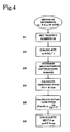
- a desired number N i of the cords 1 for a ply of a tire of a tire size of i in. is set in step S1. More specifically, the desired numbers N i are N 15 , N 16 , ... for plies for a 15 in. tire, a 16 in. tire, ..., respectively.
- An optimum desired number is dependent on the type of the cords, such as steel cords and resin cords, and hence the desired numbers N i are set depending on types of cords, respectively.
- the desired number N i for the tire size i in. is divided by i corresponding to the tire size of i in. to obtain a quotient n i in step S2.
- An integer n a nearest to the mean of the values of n i is determined in step S3.
- ni values are made in a distribution chart, in which tire size is taken on the horizontal axis and n i is taken on the vertical axis, the plots of the ni values in the chart are near a certain integer, and hence the integer n a can be determined easily.
- the integer n a is equal to an optimum number of cords to be included in the strip 3.
- the value of the integer n a namely, optimum number of cords is determined for different types of cords, respectively.
- the optimum number n a of cords of a synthetic resin was eighty-eight.
- the pitch of the cords is changed so that (n a - 1) cords are arranged in a width of ⁇ inches because the corresponding side edge parts of adjacent strips 3 are superposed such that the outermost cords of the corresponding side edge parts overlap each other as shown in Fig. 6.
- the pitch P is obtained by multiplying the temporary pitch P t by n a /(n a - 1) in step S5.
- the width w of the strips 3 is calculated by multiplying the pitch P by n a in step S6.
- the width w of the strips 3 is determined.
- the side edge parts 3a of the strip 3 are formed in a sectional shape resembling an isosceles triangle as shown in Figs. 3 and 6 so that the joint of the corresponding side edge parts of adjacent strips 3 may not be excessively thick.
- the extruder 10 forms the cord-reinforced belt 2 of a width w including n a cords 1 arranged at a pitch P.
- eighty-six cords are arranged at a pitch of 0.94 mm in a cord-reinforced belt 2 of 80.7 mm in width.
- the ply for a tire of a certain tire size includes an accurately fixed number of cords.
- the respective numbers of cords included in plies respectively for tires of tire sizes of 15 in. and 16 in. are 15n a and 16n a , respectively.
- the tire structural member for one tire of a tire size includes an accurately fixed number of cords. Therefore, increase in the weight and the cost of the tire can be prevented, and the dynamic balance and uniformity of the tire can be improved.
Landscapes
- Engineering & Computer Science (AREA)
- Textile Engineering (AREA)
- Mechanical Engineering (AREA)
- Tyre Moulding (AREA)
- Tires In General (AREA)
Claims (4)
- Verfahren zur Herstellung eines kordverstärkten Reifenstrukturelementes, das umfasst:ein Herstellen von Streifen (3), die eine Breite von annähernd π Zoll aufweisen und die durch darin eingebettete Korde (1) verstärkt sind; undeine aufeinander folgendes Anordnen einer vorher bestimmten Anzahl der Streifen (3) in einer benachbarten Seite-an-Seite Anordnung; undein Zusammenvereinigen von Seitenkantenteilen der Streifen (3), um ein kordverstärktes Reifenstrukturelement (4) zu erzeugen, gekennzeichnet durch die nachfolgenden Schritte:ein Einrichten einer gewünschten Anzahl (Ni) der Korde (1), die für eine jede der Reifengrößen (i) in Zoll in das kordverstärkte Reifenstrukturelement (4) hinein gefügt werden sollen;ein Dividieren der gewünschten Anzahl (Ni) der Korde durch eine jede der Reifengrößen (i), um einen Quotienten (ni) für eine jede Reifengröße zu berechnen, womit man Quotienten ((Ni/i) für die jeweiligen Reifengrößen erhält;ein Berechnen eines Mittelwertes aus den so erhaltenen Quotienten ((Ni/i);ein Bestimmen eines Integralteiles des Mittelwertes, der die Anzahl (na) der Korde (1) ausmachen soll, die in einen jeden der Streifen (3) eingefügt werden sollen.
- Verfahren gemäß Anspruch 1, dadurch gekennzeichnet, dass die Anzahl der Korde (1) in dem Reifenstrukturelement (4) für einen Reifen für einen jeden Typ von Korden bestimmt wird und dass die Anzahl der Korde, die in einen jeden Streifen (3) eingefügt werden soll, für einen jeden Typ von Korden bestimmt wird.
- Verfahren gemäß Anspruch 1, dadurch gekennzeichnet, dass die Anzahl der Korde (1), die in den Streifen (3) eingefügt werden, die gleiche ist wie die gewünschte Anzahl an Korden minus einen, und dass entsprechende Seitenkantenteile (3a) von benachbarten Streifen derart zusammen verbunden werden, dass die äußersten Korde in den entsprechenden Seitenkantenteilen der benachbarten Streifen sich gegenseitig überlappen.
- Verfahren gemäß Anspruch 3, dadurch gekennzeichnet, dass die Seitenkantenteile (3a) eines jeden Streifens (3) sich in der Richtung der Kanten der Streifen verjüngen.
Applications Claiming Priority (3)
| Application Number | Priority Date | Filing Date | Title |
|---|---|---|---|
| JP2002337787A JP4289874B2 (ja) | 2002-11-21 | 2002-11-21 | コード入りタイヤ構成部材の形成方法 |
| JP2002337787 | 2002-11-21 | ||
| PCT/JP2003/014880 WO2004045840A1 (ja) | 2002-11-21 | 2003-11-21 | コード入りタイヤ構成部材の形成方法 |
Publications (3)
| Publication Number | Publication Date |
|---|---|
| EP1568476A1 EP1568476A1 (de) | 2005-08-31 |
| EP1568476A4 EP1568476A4 (de) | 2006-01-25 |
| EP1568476B1 true EP1568476B1 (de) | 2008-01-02 |
Family
ID=32321857
Family Applications (1)
| Application Number | Title | Priority Date | Filing Date |
|---|---|---|---|
| EP03774124A Expired - Lifetime EP1568476B1 (de) | 2002-11-21 | 2003-11-21 | Verfahren zur herstellung einer kordverstärkten reifenkomponente |
Country Status (7)
| Country | Link |
|---|---|
| US (1) | US7449083B2 (de) |
| EP (1) | EP1568476B1 (de) |
| JP (1) | JP4289874B2 (de) |
| CN (1) | CN100488760C (de) |
| AU (1) | AU2003284619A1 (de) |
| DE (1) | DE60318483T2 (de) |
| WO (1) | WO2004045840A1 (de) |
Families Citing this family (9)
| Publication number | Priority date | Publication date | Assignee | Title |
|---|---|---|---|---|
| JP4526791B2 (ja) * | 2003-07-24 | 2010-08-18 | 株式会社ブリヂストン | タイヤ構成材の製造方法 |
| US20060137804A1 (en) * | 2004-12-23 | 2006-06-29 | Downing Daniel R | Method for making tire ply |
| US20060137814A1 (en) * | 2004-12-23 | 2006-06-29 | Downing Daniel R | Method for making reinforced elastomeric materials |
| EP1843344B1 (de) | 2005-01-28 | 2012-08-15 | Panasonic Corporation | Wiedergabevorrichtung, programm und wiedergabeverfahren |
| JP4355013B2 (ja) * | 2005-02-18 | 2009-10-28 | パナソニック株式会社 | ストリーム供給装置 |
| US8182634B2 (en) * | 2005-07-15 | 2012-05-22 | Toyo Tire & Rubber Co., Ltd. | Belt member producing method |
| JP5373772B2 (ja) | 2008-04-16 | 2013-12-18 | パナソニック株式会社 | 記録媒体、記録装置、記録方法、及び再生装置 |
| CN105984162A (zh) * | 2015-01-27 | 2016-10-05 | 青岛软控机电工程有限公司 | 帘布裁断机 |
| JP6699266B2 (ja) * | 2016-03-17 | 2020-05-27 | 横浜ゴム株式会社 | 環状体における原部材の繋ぎ合わせ位置の検出方法、タイヤの欠陥検査方法、及びタイヤの製造方法 |
Family Cites Families (11)
| Publication number | Priority date | Publication date | Assignee | Title |
|---|---|---|---|---|
| JPS5591649A (en) * | 1978-12-29 | 1980-07-11 | Yokohama Rubber Co Ltd:The | Connection of cord material |
| JPS5939538A (ja) * | 1982-08-31 | 1984-03-03 | Yokohama Rubber Co Ltd:The | タイヤのスチ−ルコ−ド配列検査装置 |
| JPH04135739A (ja) * | 1990-09-27 | 1992-05-11 | Bridgestone Corp | 帯状部材の切断貼付け方法 |
| JP3124560B2 (ja) * | 1990-12-28 | 2001-01-15 | 株式会社ブリヂストン | プライ部材の成型方法 |
| CA2097642A1 (en) * | 1993-03-19 | 1994-09-20 | Jerry Malin | Method and apparatus for fabricating a rubberized wire sheet |
| US6280556B1 (en) | 1997-11-10 | 2001-08-28 | The Yokohama Rubber Co., Ltd. | Apparatus and method for aligning and splicing strip members |
| JP2000159399A (ja) | 1998-11-25 | 2000-06-13 | Bridgestone Corp | 帯状部材の接合方法および接合装置 |
| JP2000229503A (ja) * | 1999-02-10 | 2000-08-22 | Bridgestone Corp | 空気入りラジアルタイヤ |
| JP4326112B2 (ja) | 2000-04-10 | 2009-09-02 | 株式会社ブリヂストン | タイヤカーカスの製造方法 |
| JP4894080B2 (ja) * | 2000-05-17 | 2012-03-07 | 横浜ゴム株式会社 | カーカス部材の製造方法及びその装置 |
| JP4502579B2 (ja) * | 2001-01-12 | 2010-07-14 | 株式会社ブリヂストン | タイヤ構成部材の製造方法及びその装置 |
-
2002
- 2002-11-21 JP JP2002337787A patent/JP4289874B2/ja not_active Expired - Lifetime
-
2003
- 2003-11-21 DE DE60318483T patent/DE60318483T2/de not_active Expired - Fee Related
- 2003-11-21 EP EP03774124A patent/EP1568476B1/de not_active Expired - Lifetime
- 2003-11-21 CN CNB2003801049049A patent/CN100488760C/zh not_active Expired - Fee Related
- 2003-11-21 US US10/535,846 patent/US7449083B2/en not_active Expired - Fee Related
- 2003-11-21 AU AU2003284619A patent/AU2003284619A1/en not_active Abandoned
- 2003-11-21 WO PCT/JP2003/014880 patent/WO2004045840A1/ja not_active Ceased
Also Published As
| Publication number | Publication date |
|---|---|
| CN1720131A (zh) | 2006-01-11 |
| EP1568476A4 (de) | 2006-01-25 |
| JP4289874B2 (ja) | 2009-07-01 |
| EP1568476A1 (de) | 2005-08-31 |
| JP2004167900A (ja) | 2004-06-17 |
| DE60318483D1 (de) | 2008-02-14 |
| CN100488760C (zh) | 2009-05-20 |
| DE60318483T2 (de) | 2008-12-18 |
| WO2004045840A1 (ja) | 2004-06-03 |
| US20060124227A1 (en) | 2006-06-15 |
| US7449083B2 (en) | 2008-11-11 |
| AU2003284619A1 (en) | 2004-06-15 |
Similar Documents
| Publication | Publication Date | Title |
|---|---|---|
| EP1486320B1 (de) | Verfahren zur herstellung eines dünnen kautschukglieds, kautschukwalzvorrichtung und kautschukwalzverfahren | |
| EP1568476B1 (de) | Verfahren zur herstellung einer kordverstärkten reifenkomponente | |
| JP2010208090A (ja) | プライ部材の製造方法、短冊状プライ及び空気入りタイヤ | |
| JP4194168B2 (ja) | ベルト材の供給方法 | |
| EP1674246A1 (de) | Verfahren zur Herstellung einer Reifenlage | |
| JP2003246205A (ja) | 空気入りタイヤ及びその製造方法 | |
| EP1201397B1 (de) | Vorrichtung zur Herstellung eines unvulkanisierten Gummibandes | |
| EP1674251B1 (de) | Vorrichtung zur Herstellung von Reifenbestandteilen. | |
| EP1650014A1 (de) | Verfahren zur herstellung eines reifenstrukturglieds | |
| CN101600561B (zh) | 通过应用具有不同宽度的带制造轮胎的方法 | |
| US20050178488A1 (en) | Method of manufacturing tire component member and pneumatic tire | |
| EP1555113A1 (de) | Verfahren und vorrichtung zur herstellung einer cordverstärkungslage für reifen | |
| JP4932127B2 (ja) | 空気タイヤを製造するための方法および装置 | |
| JP4251888B2 (ja) | タイヤ成形サービサーに於ける補強材の貼付け方法及びその補強材の貼付け装置 | |
| EP1674247A1 (de) | Verfahren zur Herstellung einer Reifenlage | |
| US12109773B2 (en) | Method and apparatus for forming an apex | |
| US20050183815A1 (en) | Tire ply forming apparatus and process | |
| JP2004142451A (ja) | タイヤ用コード補強層の形成方法およびコード補強層形成装置 |
Legal Events
| Date | Code | Title | Description |
|---|---|---|---|
| PUAI | Public reference made under article 153(3) epc to a published international application that has entered the european phase |
Free format text: ORIGINAL CODE: 0009012 |
|
| 17P | Request for examination filed |
Effective date: 20050601 |
|
| AK | Designated contracting states |
Kind code of ref document: A1 Designated state(s): AT BE BG CH CY CZ DE DK EE ES FI FR GB GR HU IE IT LI LU MC NL PT RO SE SI SK TR |
|
| AX | Request for extension of the european patent |
Extension state: AL LT LV MK |
|
| A4 | Supplementary search report drawn up and despatched |
Effective date: 20051213 |
|
| DAX | Request for extension of the european patent (deleted) | ||
| RBV | Designated contracting states (corrected) |
Designated state(s): DE FR HU IT |
|
| GRAP | Despatch of communication of intention to grant a patent |
Free format text: ORIGINAL CODE: EPIDOSNIGR1 |
|
| RTI1 | Title (correction) |
Free format text: METHOD OF FORMING CORD-REINFORCED TIRE STRUCTURAL MEMBER |
|
| GRAS | Grant fee paid |
Free format text: ORIGINAL CODE: EPIDOSNIGR3 |
|
| GRAA | (expected) grant |
Free format text: ORIGINAL CODE: 0009210 |
|
| AK | Designated contracting states |
Kind code of ref document: B1 Designated state(s): DE FR HU IT |
|
| REF | Corresponds to: |
Ref document number: 60318483 Country of ref document: DE Date of ref document: 20080214 Kind code of ref document: P |
|
| REG | Reference to a national code |
Ref country code: HU Ref legal event code: AG4A Ref document number: E003122 Country of ref document: HU |
|
| PLBE | No opposition filed within time limit |
Free format text: ORIGINAL CODE: 0009261 |
|
| STAA | Information on the status of an ep patent application or granted ep patent |
Free format text: STATUS: NO OPPOSITION FILED WITHIN TIME LIMIT |
|
| 26N | No opposition filed |
Effective date: 20081003 |
|
| PGFP | Annual fee paid to national office [announced via postgrant information from national office to epo] |
Ref country code: DE Payment date: 20081114 Year of fee payment: 6 |
|
| PGFP | Annual fee paid to national office [announced via postgrant information from national office to epo] |
Ref country code: IT Payment date: 20081127 Year of fee payment: 6 |
|
| PGFP | Annual fee paid to national office [announced via postgrant information from national office to epo] |
Ref country code: FR Payment date: 20081112 Year of fee payment: 6 |
|
| REG | Reference to a national code |
Ref country code: FR Ref legal event code: ST Effective date: 20100730 |
|
| PG25 | Lapsed in a contracting state [announced via postgrant information from national office to epo] |
Ref country code: FR Free format text: LAPSE BECAUSE OF NON-PAYMENT OF DUE FEES Effective date: 20091130 |
|
| PG25 | Lapsed in a contracting state [announced via postgrant information from national office to epo] |
Ref country code: DE Free format text: LAPSE BECAUSE OF NON-PAYMENT OF DUE FEES Effective date: 20100601 |
|
| PG25 | Lapsed in a contracting state [announced via postgrant information from national office to epo] |
Ref country code: IT Free format text: LAPSE BECAUSE OF NON-PAYMENT OF DUE FEES Effective date: 20091121 |
|
| PGFP | Annual fee paid to national office [announced via postgrant information from national office to epo] |
Ref country code: HU Payment date: 20191115 Year of fee payment: 17 |
|
| PG25 | Lapsed in a contracting state [announced via postgrant information from national office to epo] |
Ref country code: HU Free format text: LAPSE BECAUSE OF NON-PAYMENT OF DUE FEES Effective date: 20201122 |