US5221541A - Extruder head for elastomeric material - Google Patents
Extruder head for elastomeric material Download PDFInfo
- Publication number
- US5221541A US5221541A US07/757,742 US75774291A US5221541A US 5221541 A US5221541 A US 5221541A US 75774291 A US75774291 A US 75774291A US 5221541 A US5221541 A US 5221541A
- Authority
- US
- United States
- Prior art keywords
- passage
- section
- extrudate
- plates
- extruder head
- Prior art date
- Legal status (The legal status is an assumption and is not a legal conclusion. Google has not performed a legal analysis and makes no representation as to the accuracy of the status listed.)
- Expired - Lifetime
Links
- 239000013536 elastomeric material Substances 0.000 title description 10
- 239000000110 cooling liquid Substances 0.000 claims abstract description 7
- 238000010276 construction Methods 0.000 claims description 10
- 238000011144 upstream manufacturing Methods 0.000 claims description 6
- 230000003247 decreasing effect Effects 0.000 claims description 2
- 230000000717 retained effect Effects 0.000 claims description 2
- 239000000155 melt Substances 0.000 abstract description 5
- 229910000760 Hardened steel Inorganic materials 0.000 abstract 1
- 230000013011 mating Effects 0.000 abstract 1
- 238000001125 extrusion Methods 0.000 description 13
- 239000000463 material Substances 0.000 description 7
- 239000000523 sample Substances 0.000 description 7
- 238000001816 cooling Methods 0.000 description 5
- 230000007704 transition Effects 0.000 description 4
- 238000011161 development Methods 0.000 description 3
- 230000018109 developmental process Effects 0.000 description 3
- 235000019589 hardness Nutrition 0.000 description 3
- 229910000831 Steel Inorganic materials 0.000 description 2
- 230000008901 benefit Effects 0.000 description 2
- 239000002184 metal Substances 0.000 description 2
- 238000000034 method Methods 0.000 description 2
- 230000008569 process Effects 0.000 description 2
- 239000010959 steel Substances 0.000 description 2
- 229920005992 thermoplastic resin Polymers 0.000 description 2
- 229910000851 Alloy steel Inorganic materials 0.000 description 1
- 239000000498 cooling water Substances 0.000 description 1
- 239000012530 fluid Substances 0.000 description 1
- 238000004519 manufacturing process Methods 0.000 description 1
- 239000000203 mixture Substances 0.000 description 1
- 238000012986 modification Methods 0.000 description 1
- 230000004048 modification Effects 0.000 description 1
- 239000012768 molten material Substances 0.000 description 1
- 230000009467 reduction Effects 0.000 description 1
- 238000006467 substitution reaction Methods 0.000 description 1
- 239000012815 thermoplastic material Substances 0.000 description 1
Images


Classifications
-
- B—PERFORMING OPERATIONS; TRANSPORTING
- B29—WORKING OF PLASTICS; WORKING OF SUBSTANCES IN A PLASTIC STATE IN GENERAL
- B29C—SHAPING OR JOINING OF PLASTICS; SHAPING OF MATERIAL IN A PLASTIC STATE, NOT OTHERWISE PROVIDED FOR; AFTER-TREATMENT OF THE SHAPED PRODUCTS, e.g. REPAIRING
- B29C48/00—Extrusion moulding, i.e. expressing the moulding material through a die or nozzle which imparts the desired form; Apparatus therefor
- B29C48/25—Component parts, details or accessories; Auxiliary operations
- B29C48/78—Thermal treatment of the extrusion moulding material or of preformed parts or layers, e.g. by heating or cooling
- B29C48/86—Thermal treatment of the extrusion moulding material or of preformed parts or layers, e.g. by heating or cooling at the nozzle zone
- B29C48/87—Cooling
-
- B—PERFORMING OPERATIONS; TRANSPORTING
- B29—WORKING OF PLASTICS; WORKING OF SUBSTANCES IN A PLASTIC STATE IN GENERAL
- B29C—SHAPING OR JOINING OF PLASTICS; SHAPING OF MATERIAL IN A PLASTIC STATE, NOT OTHERWISE PROVIDED FOR; AFTER-TREATMENT OF THE SHAPED PRODUCTS, e.g. REPAIRING
- B29C48/00—Extrusion moulding, i.e. expressing the moulding material through a die or nozzle which imparts the desired form; Apparatus therefor
- B29C48/03—Extrusion moulding, i.e. expressing the moulding material through a die or nozzle which imparts the desired form; Apparatus therefor characterised by the shape of the extruded material at extrusion
- B29C48/07—Flat, e.g. panels
-
- B—PERFORMING OPERATIONS; TRANSPORTING
- B29—WORKING OF PLASTICS; WORKING OF SUBSTANCES IN A PLASTIC STATE IN GENERAL
- B29C—SHAPING OR JOINING OF PLASTICS; SHAPING OF MATERIAL IN A PLASTIC STATE, NOT OTHERWISE PROVIDED FOR; AFTER-TREATMENT OF THE SHAPED PRODUCTS, e.g. REPAIRING
- B29C48/00—Extrusion moulding, i.e. expressing the moulding material through a die or nozzle which imparts the desired form; Apparatus therefor
- B29C48/03—Extrusion moulding, i.e. expressing the moulding material through a die or nozzle which imparts the desired form; Apparatus therefor characterised by the shape of the extruded material at extrusion
- B29C48/12—Articles with an irregular circumference when viewed in cross-section, e.g. window profiles
-
- B—PERFORMING OPERATIONS; TRANSPORTING
- B29—WORKING OF PLASTICS; WORKING OF SUBSTANCES IN A PLASTIC STATE IN GENERAL
- B29C—SHAPING OR JOINING OF PLASTICS; SHAPING OF MATERIAL IN A PLASTIC STATE, NOT OTHERWISE PROVIDED FOR; AFTER-TREATMENT OF THE SHAPED PRODUCTS, e.g. REPAIRING
- B29C48/00—Extrusion moulding, i.e. expressing the moulding material through a die or nozzle which imparts the desired form; Apparatus therefor
- B29C48/25—Component parts, details or accessories; Auxiliary operations
- B29C48/30—Extrusion nozzles or dies
- B29C48/305—Extrusion nozzles or dies having a wide opening, e.g. for forming sheets
-
- B—PERFORMING OPERATIONS; TRANSPORTING
- B29—WORKING OF PLASTICS; WORKING OF SUBSTANCES IN A PLASTIC STATE IN GENERAL
- B29C—SHAPING OR JOINING OF PLASTICS; SHAPING OF MATERIAL IN A PLASTIC STATE, NOT OTHERWISE PROVIDED FOR; AFTER-TREATMENT OF THE SHAPED PRODUCTS, e.g. REPAIRING
- B29C48/00—Extrusion moulding, i.e. expressing the moulding material through a die or nozzle which imparts the desired form; Apparatus therefor
- B29C48/25—Component parts, details or accessories; Auxiliary operations
- B29C48/78—Thermal treatment of the extrusion moulding material or of preformed parts or layers, e.g. by heating or cooling
- B29C48/86—Thermal treatment of the extrusion moulding material or of preformed parts or layers, e.g. by heating or cooling at the nozzle zone
-
- B—PERFORMING OPERATIONS; TRANSPORTING
- B29—WORKING OF PLASTICS; WORKING OF SUBSTANCES IN A PLASTIC STATE IN GENERAL
- B29C—SHAPING OR JOINING OF PLASTICS; SHAPING OF MATERIAL IN A PLASTIC STATE, NOT OTHERWISE PROVIDED FOR; AFTER-TREATMENT OF THE SHAPED PRODUCTS, e.g. REPAIRING
- B29C48/00—Extrusion moulding, i.e. expressing the moulding material through a die or nozzle which imparts the desired form; Apparatus therefor
- B29C48/25—Component parts, details or accessories; Auxiliary operations
- B29C48/92—Measuring, controlling or regulating
-
- B—PERFORMING OPERATIONS; TRANSPORTING
- B29—WORKING OF PLASTICS; WORKING OF SUBSTANCES IN A PLASTIC STATE IN GENERAL
- B29C—SHAPING OR JOINING OF PLASTICS; SHAPING OF MATERIAL IN A PLASTIC STATE, NOT OTHERWISE PROVIDED FOR; AFTER-TREATMENT OF THE SHAPED PRODUCTS, e.g. REPAIRING
- B29C2948/00—Indexing scheme relating to extrusion moulding
- B29C2948/92—Measuring, controlling or regulating
- B29C2948/92009—Measured parameter
- B29C2948/92019—Pressure
-
- B—PERFORMING OPERATIONS; TRANSPORTING
- B29—WORKING OF PLASTICS; WORKING OF SUBSTANCES IN A PLASTIC STATE IN GENERAL
- B29C—SHAPING OR JOINING OF PLASTICS; SHAPING OF MATERIAL IN A PLASTIC STATE, NOT OTHERWISE PROVIDED FOR; AFTER-TREATMENT OF THE SHAPED PRODUCTS, e.g. REPAIRING
- B29C2948/00—Indexing scheme relating to extrusion moulding
- B29C2948/92—Measuring, controlling or regulating
- B29C2948/92009—Measured parameter
- B29C2948/92209—Temperature
-
- B—PERFORMING OPERATIONS; TRANSPORTING
- B29—WORKING OF PLASTICS; WORKING OF SUBSTANCES IN A PLASTIC STATE IN GENERAL
- B29C—SHAPING OR JOINING OF PLASTICS; SHAPING OF MATERIAL IN A PLASTIC STATE, NOT OTHERWISE PROVIDED FOR; AFTER-TREATMENT OF THE SHAPED PRODUCTS, e.g. REPAIRING
- B29C2948/00—Indexing scheme relating to extrusion moulding
- B29C2948/92—Measuring, controlling or regulating
- B29C2948/92323—Location or phase of measurement
- B29C2948/92361—Extrusion unit
- B29C2948/92409—Die; Nozzle zone
-
- B—PERFORMING OPERATIONS; TRANSPORTING
- B29—WORKING OF PLASTICS; WORKING OF SUBSTANCES IN A PLASTIC STATE IN GENERAL
- B29C—SHAPING OR JOINING OF PLASTICS; SHAPING OF MATERIAL IN A PLASTIC STATE, NOT OTHERWISE PROVIDED FOR; AFTER-TREATMENT OF THE SHAPED PRODUCTS, e.g. REPAIRING
- B29C2948/00—Indexing scheme relating to extrusion moulding
- B29C2948/92—Measuring, controlling or regulating
- B29C2948/92504—Controlled parameter
- B29C2948/92704—Temperature
-
- B—PERFORMING OPERATIONS; TRANSPORTING
- B29—WORKING OF PLASTICS; WORKING OF SUBSTANCES IN A PLASTIC STATE IN GENERAL
- B29C—SHAPING OR JOINING OF PLASTICS; SHAPING OF MATERIAL IN A PLASTIC STATE, NOT OTHERWISE PROVIDED FOR; AFTER-TREATMENT OF THE SHAPED PRODUCTS, e.g. REPAIRING
- B29C2948/00—Indexing scheme relating to extrusion moulding
- B29C2948/92—Measuring, controlling or regulating
- B29C2948/92819—Location or phase of control
- B29C2948/92857—Extrusion unit
- B29C2948/92904—Die; Nozzle zone
Definitions
- the present invention relates to an extruder for elastomeric material, and more particularly, to an extruder head for producing tire components.
- elastomeric materials such as rubber
- elastomeric materials must be processed at relatively high pressures, notably in the range of 1,000 to 10,000 p.s.i., compared to thermoplastic materials, and the temperature of the molten mass of elastomeric material must be controlled in a relatively narrow range of 210° to 236° F., for instance.
- Channels for a cooling liquid are provided in the tubular insert member and communicate with conduits in at least one of the two plates in the first section and to a source of cooling liquid to cool the wall of the tubular member forming the extrudate passage.
- a third section includes at least a pair of block members mated together and bolted to the first section and defining a bore co-extensive with the axis of the extrudate passage.
- a tubular insert is provided in at least a portion of the bore to form an extension of the extrudate passage downstream of the first section.
- a movable die assembly is bolted to the third section.
- a filter 36 will also be located in the passage 22 and held in a seat provided in the plate 28.
- the purpose of hinging the plate 28 to the plate 26 by means of hinge 32 is to allow easier access to the filter 36 which must be changed from time to time.
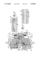
- the die plate 54 which is readily replaced is held by means of sliding wedges 56 and 58 held by wedge brackets 60 and 62 bolted to the respective lower block 46 and upper block 48.
- the wedges are operated by reciprocation means, such as piston and cylinder arrangements 68 and 70 which are located in brackets 64 and 66 respectively.
- the brackets 60, 62 and the cylinders 68, 70 are best seen in FIGS. 1 and 2.
- Blocks 46 and 48 can be mounted to plate 26 by means of bolts 72 shown in FIG. 2.
Landscapes
- Engineering & Computer Science (AREA)
- Mechanical Engineering (AREA)
- Physics & Mathematics (AREA)
- Thermal Sciences (AREA)
- Manufacturing & Machinery (AREA)
- Extrusion Moulding Of Plastics Or The Like (AREA)
Abstract
Description
Claims (5)
Priority Applications (1)
| Application Number | Priority Date | Filing Date | Title |
|---|---|---|---|
| US07/757,742 US5221541A (en) | 1991-09-11 | 1991-09-11 | Extruder head for elastomeric material |
Applications Claiming Priority (1)
| Application Number | Priority Date | Filing Date | Title |
|---|---|---|---|
| US07/757,742 US5221541A (en) | 1991-09-11 | 1991-09-11 | Extruder head for elastomeric material |
Publications (1)
| Publication Number | Publication Date |
|---|---|
| US5221541A true US5221541A (en) | 1993-06-22 |
Family
ID=25049039
Family Applications (1)
| Application Number | Title | Priority Date | Filing Date |
|---|---|---|---|
| US07/757,742 Expired - Lifetime US5221541A (en) | 1991-09-11 | 1991-09-11 | Extruder head for elastomeric material |
Country Status (1)
| Country | Link |
|---|---|
| US (1) | US5221541A (en) |
Cited By (18)
| Publication number | Priority date | Publication date | Assignee | Title |
|---|---|---|---|---|
| US5762975A (en) * | 1995-02-08 | 1998-06-09 | Compex Gmbh Compoundier-Und Extrusionsanlagen | Die head fitted to the outlet of an extruder |
| WO1999022927A1 (en) * | 1997-10-31 | 1999-05-14 | The Goodyear Tire And Rubber Company | Universal flow channel |
| US5908642A (en) * | 1995-03-15 | 1999-06-01 | Machinefabriek "De Rollepaal" B.V. | Extrusion head for plastics extruder |
| US5997272A (en) * | 1996-03-27 | 1999-12-07 | Xerox Corporation | Extruder die insert plate system |
| US6244849B1 (en) * | 1999-03-26 | 2001-06-12 | Entek Manufacturing Inc. | Extruder die assembly |
| US6340123B1 (en) | 1997-10-31 | 2002-01-22 | Ching-Chin Lee | Universal flow channel |
| US20020063357A1 (en) * | 2000-11-22 | 2002-05-30 | Masahiko Ohki | Method and apparatus for rubber extruding |
| EP1201397A3 (en) * | 2000-10-23 | 2002-12-04 | Sumitomo Rubber Industries Limited | Apparatus for making unvulcanised rubber tape |
| WO2003066313A1 (en) * | 2002-02-05 | 2003-08-14 | Pirelli Pneumatici S.P.A. | Method for manufacturing a tyre and extruder used thereby |
| US20050092365A1 (en) * | 2003-10-28 | 2005-05-05 | Rawes Godfrey D. | Extrusion assembly |
| US20060105072A1 (en) * | 2003-06-18 | 2006-05-18 | Extrutech International, Inc. | Polymer processing system including compression chamber and method for using same |
| WO2007015763A1 (en) * | 2005-08-01 | 2007-02-08 | Dow Global Technologies Inc. | Extrusion die and process for producing an extruded filled polymer composition |
| US20070029029A1 (en) * | 2005-08-04 | 2007-02-08 | Koch Brian R | Method for forming elastomeric tire component and a tire |
| US20070031529A1 (en) * | 2005-08-04 | 2007-02-08 | Koch Brian R | Apparatus for forming elastomeric tire component and a tire |
| EP1749649A3 (en) * | 2005-08-04 | 2007-10-24 | The Goodyear Tire & Rubber Company | A method for forming an elastomeric component |
| EP2463076A1 (en) * | 2010-12-10 | 2012-06-13 | The Goodyear Tire & Rubber Company | Extruder die assembly |
| US20150209994A1 (en) * | 2012-07-13 | 2015-07-30 | Lev Anatolyevich Gubenko | Method for forming long sheets out of plasticized materials and a device for implementing the same |
| US20160339634A1 (en) * | 2015-05-21 | 2016-11-24 | Kenneth Fuller | Printer for three dimensional printing |
Citations (20)
| Publication number | Priority date | Publication date | Assignee | Title |
|---|---|---|---|---|
| SU172210A1 (en) * | И. А. Гольдбепг , П. Тютю ник | DEVICE FOR PRESSING PREPARATIONS OR PRODUCTS FROM ABRASIVE POWDER MASS | ||
| DE588555C (en) * | 1933-11-24 | Hermann Hullen | Mold for briquette extrusion | |
| US2092410A (en) * | 1934-03-06 | 1937-09-07 | Harley T Wheeler | Interchangeable mold |
| US2245608A (en) * | 1938-12-19 | 1941-06-17 | George D Rogers | Die |
| US2728943A (en) * | 1953-09-29 | 1956-01-03 | Celanese Corp | Extrusion apparatus |
| US2897541A (en) * | 1956-12-03 | 1959-08-04 | Nixon Nitration Works | Apparatus for extruding sheets with striped pattern |
| US3032822A (en) * | 1959-05-05 | 1962-05-08 | Union Carbide Corp | Extrusion control |
| US3551951A (en) * | 1968-03-12 | 1971-01-05 | Walter Hugo Schiesser | Multiple extruder head for extruders |
| US3570062A (en) * | 1969-02-14 | 1971-03-16 | Pennwalt Corp | Midstream radial valve for in-line extrusion of viscous thermoplastics |
| US3676535A (en) * | 1969-11-07 | 1972-07-11 | Leslie H Juel | Method and apparatus for controlling orientation of needle-like carbon particles in extruded carbon stock |
| US3871810A (en) * | 1972-11-20 | 1975-03-18 | Uniroyal Inc | Extruder and roller-die combination |
| US4015925A (en) * | 1972-02-10 | 1977-04-05 | Certain-Teed Products Corporation | Extrusion equipment and especially die structure for making plastic siding |
| US4164388A (en) * | 1978-06-16 | 1979-08-14 | International Spike, Inc. | Extrusion die assembly |
| US4238538A (en) * | 1978-12-21 | 1980-12-09 | E. I. Du Pont De Nemours And Company | Method of and apparatus for ram-extrusion of aromatic polyimide and polyamide resins, and shaped articles formed using such method and apparatus |
| SU835802A1 (en) * | 1978-07-24 | 1981-06-07 | Ленинградский Ордена Трудового Крас-Ного Знамени Технологический Институтим.Ленсовета | Polymer-extrusion head |
| US4280801A (en) * | 1979-05-30 | 1981-07-28 | Crompton & Knowles Corporation | Crosshead |
| SU520744A1 (en) * | 1974-03-06 | 1984-07-07 | Предприятие П/Я В-8406 | Filter for extruder |
| DE3503721A1 (en) * | 1985-02-05 | 1986-08-07 | Hoechst Ag, 6230 Frankfurt | Slit die for extruding a thermoplastic |
| US4826422A (en) * | 1988-01-13 | 1989-05-02 | The Firestone Tire & Rubber Company | Restriction insert for an extrusion die |
| US4892473A (en) * | 1988-12-22 | 1990-01-09 | Bridgestone/Firestone, Inc. | Head for extrusion of elastomeric contour innerliner |
-
1991
- 1991-09-11 US US07/757,742 patent/US5221541A/en not_active Expired - Lifetime
Patent Citations (20)
| Publication number | Priority date | Publication date | Assignee | Title |
|---|---|---|---|---|
| DE588555C (en) * | 1933-11-24 | Hermann Hullen | Mold for briquette extrusion | |
| SU172210A1 (en) * | И. А. Гольдбепг , П. Тютю ник | DEVICE FOR PRESSING PREPARATIONS OR PRODUCTS FROM ABRASIVE POWDER MASS | ||
| US2092410A (en) * | 1934-03-06 | 1937-09-07 | Harley T Wheeler | Interchangeable mold |
| US2245608A (en) * | 1938-12-19 | 1941-06-17 | George D Rogers | Die |
| US2728943A (en) * | 1953-09-29 | 1956-01-03 | Celanese Corp | Extrusion apparatus |
| US2897541A (en) * | 1956-12-03 | 1959-08-04 | Nixon Nitration Works | Apparatus for extruding sheets with striped pattern |
| US3032822A (en) * | 1959-05-05 | 1962-05-08 | Union Carbide Corp | Extrusion control |
| US3551951A (en) * | 1968-03-12 | 1971-01-05 | Walter Hugo Schiesser | Multiple extruder head for extruders |
| US3570062A (en) * | 1969-02-14 | 1971-03-16 | Pennwalt Corp | Midstream radial valve for in-line extrusion of viscous thermoplastics |
| US3676535A (en) * | 1969-11-07 | 1972-07-11 | Leslie H Juel | Method and apparatus for controlling orientation of needle-like carbon particles in extruded carbon stock |
| US4015925A (en) * | 1972-02-10 | 1977-04-05 | Certain-Teed Products Corporation | Extrusion equipment and especially die structure for making plastic siding |
| US3871810A (en) * | 1972-11-20 | 1975-03-18 | Uniroyal Inc | Extruder and roller-die combination |
| SU520744A1 (en) * | 1974-03-06 | 1984-07-07 | Предприятие П/Я В-8406 | Filter for extruder |
| US4164388A (en) * | 1978-06-16 | 1979-08-14 | International Spike, Inc. | Extrusion die assembly |
| SU835802A1 (en) * | 1978-07-24 | 1981-06-07 | Ленинградский Ордена Трудового Крас-Ного Знамени Технологический Институтим.Ленсовета | Polymer-extrusion head |
| US4238538A (en) * | 1978-12-21 | 1980-12-09 | E. I. Du Pont De Nemours And Company | Method of and apparatus for ram-extrusion of aromatic polyimide and polyamide resins, and shaped articles formed using such method and apparatus |
| US4280801A (en) * | 1979-05-30 | 1981-07-28 | Crompton & Knowles Corporation | Crosshead |
| DE3503721A1 (en) * | 1985-02-05 | 1986-08-07 | Hoechst Ag, 6230 Frankfurt | Slit die for extruding a thermoplastic |
| US4826422A (en) * | 1988-01-13 | 1989-05-02 | The Firestone Tire & Rubber Company | Restriction insert for an extrusion die |
| US4892473A (en) * | 1988-12-22 | 1990-01-09 | Bridgestone/Firestone, Inc. | Head for extrusion of elastomeric contour innerliner |
Cited By (26)
| Publication number | Priority date | Publication date | Assignee | Title |
|---|---|---|---|---|
| US5762975A (en) * | 1995-02-08 | 1998-06-09 | Compex Gmbh Compoundier-Und Extrusionsanlagen | Die head fitted to the outlet of an extruder |
| US5908642A (en) * | 1995-03-15 | 1999-06-01 | Machinefabriek "De Rollepaal" B.V. | Extrusion head for plastics extruder |
| US5997272A (en) * | 1996-03-27 | 1999-12-07 | Xerox Corporation | Extruder die insert plate system |
| WO1999022927A1 (en) * | 1997-10-31 | 1999-05-14 | The Goodyear Tire And Rubber Company | Universal flow channel |
| US6340123B1 (en) | 1997-10-31 | 2002-01-22 | Ching-Chin Lee | Universal flow channel |
| US6244849B1 (en) * | 1999-03-26 | 2001-06-12 | Entek Manufacturing Inc. | Extruder die assembly |
| EP1201397A3 (en) * | 2000-10-23 | 2002-12-04 | Sumitomo Rubber Industries Limited | Apparatus for making unvulcanised rubber tape |
| US6688872B2 (en) * | 2000-10-23 | 2004-02-10 | Sumitomo Rubber Industries, Ltd. | Apparatus for making unvulcanized rubber tape |
| US6776946B2 (en) * | 2000-11-22 | 2004-08-17 | Sumitomo Rubber Industries, Ltd. | Method and apparatus for rubber extruding |
| US20020063357A1 (en) * | 2000-11-22 | 2002-05-30 | Masahiko Ohki | Method and apparatus for rubber extruding |
| US20050127568A1 (en) * | 2002-02-05 | 2005-06-16 | Rodolfo Noto | Method for manufacturing a tyre and extruder used thereby |
| WO2003066313A1 (en) * | 2002-02-05 | 2003-08-14 | Pirelli Pneumatici S.P.A. | Method for manufacturing a tyre and extruder used thereby |
| US8192663B2 (en) | 2002-02-05 | 2012-06-05 | Pirelli Pneumaticai S.P.A. | Method for manufacturing a tyre and extruder for producing a semi-finished elastomeric product |
| US20060105072A1 (en) * | 2003-06-18 | 2006-05-18 | Extrutech International, Inc. | Polymer processing system including compression chamber and method for using same |
| US20050092365A1 (en) * | 2003-10-28 | 2005-05-05 | Rawes Godfrey D. | Extrusion assembly |
| CN101232987B (en) * | 2005-08-01 | 2010-08-25 | 陶氏环球技术公司 | Extrusion dies and processes for producing extruded filled polymer compositions |
| US20090146339A1 (en) * | 2005-08-01 | 2009-06-11 | Malone Bruce A | Extrusion Die and Process for Producing an Extruded Filled Polymer Composition |
| WO2007015763A1 (en) * | 2005-08-01 | 2007-02-08 | Dow Global Technologies Inc. | Extrusion die and process for producing an extruded filled polymer composition |
| US20070031529A1 (en) * | 2005-08-04 | 2007-02-08 | Koch Brian R | Apparatus for forming elastomeric tire component and a tire |
| EP1749649A3 (en) * | 2005-08-04 | 2007-10-24 | The Goodyear Tire & Rubber Company | A method for forming an elastomeric component |
| US7780809B2 (en) | 2005-08-04 | 2010-08-24 | The Goodyear Tire & Rubber Company | Method for forming elastomeric tire component and a tire |
| US20070029029A1 (en) * | 2005-08-04 | 2007-02-08 | Koch Brian R | Method for forming elastomeric tire component and a tire |
| EP2463076A1 (en) * | 2010-12-10 | 2012-06-13 | The Goodyear Tire & Rubber Company | Extruder die assembly |
| US20150209994A1 (en) * | 2012-07-13 | 2015-07-30 | Lev Anatolyevich Gubenko | Method for forming long sheets out of plasticized materials and a device for implementing the same |
| US20160339634A1 (en) * | 2015-05-21 | 2016-11-24 | Kenneth Fuller | Printer for three dimensional printing |
| US10245783B2 (en) * | 2015-05-21 | 2019-04-02 | Kenneth Fuller | Printer for three dimensional printing |
Similar Documents
| Publication | Publication Date | Title |
|---|---|---|
| US5221541A (en) | Extruder head for elastomeric material | |
| US3899276A (en) | Annular extrusion die with back pressure control | |
| US4137027A (en) | Extruderhead | |
| US3303247A (en) | Extrusion head for plastic tubing | |
| US3850568A (en) | Extrusion die with adjustable profile | |
| US5023029A (en) | Method and apparatus for producing pipe with annular ribs | |
| US2639464A (en) | Extrusion apparatus | |
| DE69102219T2 (en) | Coextrusion machine and use of a rigid nozzle section to change the outer profile of a tubular extrudate. | |
| US3241183A (en) | Film extrusion die | |
| DE69105873T2 (en) | Coextrusion device and method using an elastic die to change the outer profile of a tubular extrusion. | |
| EP2148773B1 (en) | Device and method for manufacturing of plastic articles by extrusion blow moulding | |
| CA1319478C (en) | Extrusion die having elongated extrusion nozzle which facilitates tool changes | |
| US3497582A (en) | Plastic extrusion | |
| US3212134A (en) | Extrusion die assembly | |
| US8273276B2 (en) | Roller die preformer for wide extrusions | |
| EP0265420B1 (en) | Extrusion die for extruding plastics materials | |
| US5935493A (en) | Method for blow-moulding | |
| EP0838322B1 (en) | A method of and apparatus for blow-moulding | |
| JPH1058110A (en) | Multiple injection die casting apparatus | |
| US4904171A (en) | Lubricating apparatus for clay extruders | |
| US2760227A (en) | Adjustable extruder head | |
| JP2582292B2 (en) | Blow molding machine dies | |
| RU2213007C2 (en) | Device for filtering of polymer material melt | |
| JPH08174628A (en) | Switching mold equipment for extrusion molding | |
| JP2776451B2 (en) | Blow molding machine with flat dies |
Legal Events
| Date | Code | Title | Description |
|---|---|---|---|
| AS | Assignment |
Owner name: BRIDGESTONE/FIRESTONE, INC., A CORP. OF OH, OHIO Free format text: ASSIGNMENT OF ASSIGNORS INTEREST.;ASSIGNORS:ARBOUR, GAETAN;ELIA, GERARDO P.;ELIA, MARGARET N.;AND OTHERS;REEL/FRAME:005853/0875;SIGNING DATES FROM 19910830 TO 19910911 |
|
| STCF | Information on status: patent grant |
Free format text: PATENTED CASE |
|
| FEPP | Fee payment procedure |
Free format text: PAYOR NUMBER ASSIGNED (ORIGINAL EVENT CODE: ASPN); ENTITY STATUS OF PATENT OWNER: LARGE ENTITY |
|
| FPAY | Fee payment |
Year of fee payment: 4 |
|
| AS | Assignment |
Owner name: BRIDGESTONE/FIRESTONE RESEARCH, INC., OHIO Free format text: ASSIGNMENT OF ASSIGNORS INTEREST;ASSIGNOR:BRIDGESTONE/FIRESTONE, INC.;REEL/FRAME:009719/0442 Effective date: 19980601 |
|
| FPAY | Fee payment |
Year of fee payment: 8 |
|
| AS | Assignment |
Owner name: BRIDGESTONE/FIRESTONE RESEARCH, LLC, OHIO Free format text: ACKNOWLEDGEMENT OF CONVERSION;ASSIGNOR:BRIDGESTONE/FIRESTONE RESEARCH, INC.;REEL/FRAME:012322/0614 Effective date: 20011128 |
|
| AS | Assignment |
Owner name: BRIDGESTONE/FIRESTONE NORTH AMERICAN TIRE, LLC, TE Free format text: ASSIGNMENT OF ASSIGNORS INTEREST;ASSIGNOR:BRIDGESTONE/FIRESTONE RESEARCH, LLC;REEL/FRAME:012333/0690 Effective date: 20011130 |
|
| FPAY | Fee payment |
Year of fee payment: 12 |