EP1198637B1 - Siebvorrichtung mit axial einstellbarem öffnungsring - Google Patents
Siebvorrichtung mit axial einstellbarem öffnungsring Download PDFInfo
- Publication number
- EP1198637B1 EP1198637B1 EP00915652A EP00915652A EP1198637B1 EP 1198637 B1 EP1198637 B1 EP 1198637B1 EP 00915652 A EP00915652 A EP 00915652A EP 00915652 A EP00915652 A EP 00915652A EP 1198637 B1 EP1198637 B1 EP 1198637B1
- Authority
- EP
- European Patent Office
- Prior art keywords
- ring
- screening apparatus
- screen
- bottom portion
- slot
- Prior art date
- Legal status (The legal status is an assumption and is not a legal conclusion. Google has not performed a legal analysis and makes no representation as to the accuracy of the status listed.)
- Expired - Lifetime
Links
- 238000012216 screening Methods 0.000 title claims abstract description 41
- 239000000725 suspension Substances 0.000 claims abstract description 28
- 230000000694 effects Effects 0.000 description 6
- 239000012535 impurity Substances 0.000 description 3
- STECJAGHUSJQJN-USLFZFAMSA-N LSM-4015 Chemical compound C1([C@@H](CO)C(=O)OC2C[C@@H]3N([C@H](C2)[C@@H]2[C@H]3O2)C)=CC=CC=C1 STECJAGHUSJQJN-USLFZFAMSA-N 0.000 description 1
- 239000011362 coarse particle Substances 0.000 description 1
- 239000012467 final product Substances 0.000 description 1
- 230000000149 penetrating effect Effects 0.000 description 1
- 230000002000 scavenging effect Effects 0.000 description 1
- -1 scrap Substances 0.000 description 1
- 238000007789 sealing Methods 0.000 description 1
- XLYOFNOQVPJJNP-UHFFFAOYSA-N water Substances O XLYOFNOQVPJJNP-UHFFFAOYSA-N 0.000 description 1
Images
Classifications
-
- D—TEXTILES; PAPER
- D21—PAPER-MAKING; PRODUCTION OF CELLULOSE
- D21D—TREATMENT OF THE MATERIALS BEFORE PASSING TO THE PAPER-MAKING MACHINE
- D21D5/00—Purification of the pulp suspension by mechanical means; Apparatus therefor
- D21D5/02—Straining or screening the pulp
- D21D5/06—Rotary screen-drums
Definitions
- the screening apparatus comprises a screen housing with a screen chamber, which inward is defined by a rotary tubular screen means, outward is defined by an outer defining surface, and downward is defined by a bottom portion. Lowermost on the screen means a knob ring is located. Between the knob ring and a slot ring a gap is formed.
- the screening apparatus further comprises an inlet for fibrous suspension to the screening apparatus, a reject outlet for reject from the screen chamber (2) and an accept outlet for accept from the screening apparatus.
- a screening apparatus of this kind is used at coarse and fine screening of pulp suspensions, preferably for fractionating or separating impurities and other foreign matter not desired to be included in the final product, such as shives, knots, coarse particles, scrap, stones or incompletely digested or not refined chip pieces.
- the screening apparatus usually is pressurized.
- the pulp suspension to be screened is introduced via an inlet to the screen chamber where the accepted fraction, the accept, flows through the rotating screen means and into an accept chamber.
- the accept is then guided down into a lower accept chamber and out through the accept outlet.
- the lower accept chamber has the same outer diameter as the screen chamber and is located below the same.
- the pulp suspension portion, which does not pass through the screen means (the reject) is discharged via the reject outlet, which usually is provided as a tangential outlet in the lower portion of the screen chamber.
- a certain pump effect is obtained in the gap between the knob ring and slot ring. This implies that accept passes through the gap and out into the screen chamber and, thus, prevents pulp suspension from the screen chamber to pass through the gap.
- the knob ring and slot ring can be given a greater extension in radial direction.
- the slot ring constitutes one unit with the bottom portion.
- the knob ring and slot ring are subjected to wear.
- the gap increases in size, which results in that greater amounts of accept can pass through the gap, at the same time as the pump effect deteriorates.
- pulp suspension from the screen chamber can pass through the gap.
- the gap preferably shall not be wider than the greatest opening in the screen means.
- the screening apparatus For controlling the gap width, the screening apparatus is stopped, emptied and scavenged. Thereafter the screening apparatus is dismantled for making the gap width accessible to be measured. If the gap width is too great, it can be adjusted either by exchanging the entire screen means or by repairing the knob ring and/or slot ring in such a way that its original thickness is restored.
- the present invention indicates an apparatus, at which the measuring and adjusting of the gap width can be carried out much faster and considerably simpler than by known art.
- the gap width thereby can be adjusted as often as it is required for maintaining always a desired gap width.
- the slot ring at the invention is movable in axial direction in relation to the bottom portion by means of at least one gap adjustment device. Every gap adjustment device is located in the bottom portion and can be operated from the outside of the screening apparatus. The gap width thereby can be measured and adjusted without requiring the screening apparatus to be emptied of pulp suspension, cleaned and dismantled.
- the bottom portion preferably has its lower side on the outside of the screening apparatus. This implies that the lower accept chamber, which in known art is located below the screen chamber, is given a limited outer diameter, so that the lower accept chamber has a diameter, which preferably at maximum is of equal size as the diameter of the lowermost portion of the screen means.
- the slot ring usually has not such a great extension in radial direction.
- the lower accept chamber can be in the way for the gap adjustment device.
- the slot ring therefore, preferably is located on a support means provided in the screen chamber at the bottom portion.
- the support means is given at least such an extension in radial direction, that the gap adjustment device can be placed easily accessible outside the lower accept chamber.
- the slot ring should be located so that pulp suspension substantially cannot pass between the slot ring and bottom portion, that is between the screen chamber and lower accept chamber.
- the screening apparatus comprises a support means is the possibility of making at least a part of the support means exchangeable. This exchangeable part can then be utilized as wearing part.
- the support means can be formed as an outer support ring and an inner support ring.
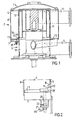
- the screening apparatus in Fig. 1 comprises a pressurized screen housing 1 with an upper portion 2, the diameter of which is greater than the lower portion 3 of the screen housing 1.
- a screen chamber 4 is located which inward is defined by a rotation symmetric rotary tubular screen means 5, outward is defined by an outer defining surface 6. and downward is defined by a bottom portion 7. which has its lower side on the outside of the screening apparatus.
- a gap 10 is formed between a knob ring 8 located on the lowermost portion of the screen means 5 and a slot ring 9 .
- the fibrous suspension to be separated which in this case is a pulp suspension. is introduced via an inlet 11 in the upper portion 2 of the screen housing 1 to the screen chamber 4.
- the accepted fraction (the accept) of the pulp suspension flows through the rotating screen means 5 and into an accept chamber 12.
- the accept flows thereafter down to a lower accept chamber 13 and out through the accept outlet 14.
- accept flows from the accept chamber 12 through the gap 10 and out into the screen chamber 4.
- the pulp suspension in the screen chamber 4 is thereby prevented from flowing into the accept chamber 12.
- the slot ring 9 is located tightly fitting on a support means 16. which is provided in the screen chamber 4 at the bottom portion 7.
- the support means 16 extends over the entire bottom portion 7 and is divided into an outer and an inner support ring 17. 18 where the slot ring 9 is formed as one unit with the inner support ring 18.
- the outer support ring 17 is detachably fastened on the bottom portion 7.
- the inner support ring 18 with the slot ring 9 is by means of at least one gap adjustment device 19 movable in axial direction. Every gap adjustment device 19 is located at the bottom portion 7 and operable from the outside of the screening apparatus. The gap width, thus. can be changed from the outside of the screening apparatus.
- the gap adjustment device 19 comprises a screw means 20, which has threads with a definite pitch.
- the screw means 20 extends through a hole in the bottom portion 7 and is fastened in the inner support ring 17, and extends further through a hole in a yoke 21 attached below the bottom portion 7.
- the slot ring 9 is moved by the gap adjustment device 19 all the way to the knob ring 8. From this position the slot ring 9. and thereby the inner support ring 18, are moved by the gap adjustment device 19 back from the knob ring 8 8 until the desired gap width is achieved.
- the nuts 22 and 23 are turned. Knowledge of the pitch angle of the threads of the screw means 20 and of the turned angle of the nuts 22 and 23 renders it possible to calculate the width of the gap 10.
- the gap adjustment device can be designed in a different way.
- the hole through the bottom portion for example, can be threaded on the inside, and the threads of the screw means thereby work against the threads in the hole of the bottom portion, when the slot ring is to be moved.
- the outer support ring 17 is arranged so against the inner support ring 18, that the pulp suspension substantially cannot pass between the outer and inner support ring 17, 18 and, thus. substantially cannot pass between the inner support ring 18 and bottom portion 7.
- the outer and inner support ring 17, 18 must run overlap so much that they are located against each other even when the slot ring 9 is moved up against the knob ring 8.
- gap adjustment device is of the kind appearing from the embodiment shown, preferably four gap adjustment devices 19 are arranged symmetrically on the bottom portion 7.
- the support means 16 When the support means 16 is formed as one unit. i.e. when the outer and inner support ring 17, 18 are formed as one unit, the support means 16 should extend all the way out to the outer defining surface 6 of the screen chamber, in order to prevent pulp suspension from penetrating in between the support means 16 and bottom portion 7 when the gap width is being adjusted.
- the gap adjustment device 19 must be arranged so as to ensure that the support means 16 is not tilted when the gap width shall be changed. This can be effected by also arranging the gap adjustment devices 19, which work against the outer support ring 17.
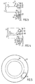
- FIG. 3 another embodiment of the invention is shown.
- the outer support ring 17 here is one unit with the bottom portion 7, and the extension of the inner support ring 18 in axial direction coincides with the extension of the slot ring 9 in radial direction.
- Fig. 4 shows still another embodiment of the invention.
- the inner support ring 18 is curved and partially guided in a groove between the bottom portion 7 and outer support ring 17.
- the reject outlet 15 When the reject outlet 15 is an opening of a definite size in the bottom portion 7 of the screen chamber 4, a corresponding opening of a definite size is provided in the support means 16.
- the reject outlet 15 thereby becomes the congruent portion of the two openings.
- the size of the congruent portion of the two openings can be changed by turning the support ring 17.
- Fig. 5 the reject outlet 15 is shown when the outer support ring 17 is turned so that the two openings are not congruent entirely.
- the support means 16 preferably is arranged so as to extend over the entire bottom portion 7, and the outer support ring 17 is made detachable on the bottom portion 7.
- the outer support ring 17, thus, can be exchanged when it is worn and thereby serve as an exchangeable wear piece as protection against wear in the screen chamber 4.
- the support means (16) can be placed so that it extends a distance up over the outer defining surface 6 of the screen chamber.
- the gap width can be adjusted without requiring the screening apparatus to be dismantled and emptied of pulp suspension. In this case a certain portion of pulp suspension is found in the gap.
- the screen means By rotating the screen means and at the same time slowly to move the slot ring against the knob ring, the gap is cleaned. If it is desired to adjust the gap width with very high accuracy. the screening apparatus, however, must be emptied and scavenged clean, before adjustment of the gap width is carried out.
- the scavenging operation is carried out in that, for example, water is fed into the screening apparatus through one of its inlets or outlets.
- a sealing means for example, can be placed in the lower accept chamber.
- the screen means 5 can be of any kind of screen means with screen openings of a suitable size for passing through the desired portion of the pulp suspension.
- the screen means for example, can have slits with openings between 0.1 mm and 0.5 mm, or holes with hole diameter between 0.1 mm and 12 mm.
- a screening apparatus according to the invention can be used both detached and in combination with other screening apparatuses in a common screen housing.
- the inlets and outlets of the screening apparatus can be located in other places and their number be greater than indicated at the embodiment shown.
Landscapes
- Engineering & Computer Science (AREA)
- Mechanical Engineering (AREA)
- Paper (AREA)
- Investigating Or Analysing Biological Materials (AREA)
- Manufacture, Treatment Of Glass Fibers (AREA)
- Filtration Of Liquid (AREA)
- Separation Of Solids By Using Liquids Or Pneumatic Power (AREA)
Claims (8)
- Siebvorrichtung zur Trennen von fasrigen Suspensionen, vorzugsweise Pulpesuspensionen, umfassend ein Siebgehäuse (1) mit einer Siebkammer (4), die nach innen durch ein drehbares, rohrförmiges Siebmittel (5) mit einem Verdickungsring (8) begrenzt ist, der in der untersten Position an dem Siebmittel (5) angeordnet ist, die nach außen durch eine äußere Begrenzungsfläche (6) begrenzt ist und die nach unten durch einen Bodenbereich (7) begrenzt ist, einen Spalt (10) zwischen dem Verdickungsring (8) und einem Schlitzring (9), wobei die Siebvorrichtung weiter umfasst einen Einlass (11) für eine fasrige Suspension zu der Siebvorrichtung, einen Ausschussauslass (15) für den Ausschuss aus der Siebkammer (4) und einen Gutstoffauslass (14) für den Gutstoff aus der Siebvorrichtung, dadurch gekennzeichnet, dass der Schlitzring (9) in axialer Richtung mit Bezug auf den Bodenbereich (7) mittels mindestens einer Spalteinstelleinrichtung (19) bewegbar und so angeordnet ist, dass im Wesentlichen verhindert ist, dass die fasrige Suspension zwischen dem Schlitzring (9) und dem Bodenbereich (7) hindurchtritt, dass jede Spalteinstelleinrichtung (19) im Bodenbereich (7) angeordnet und von außerhalb der Siebvorrichtung aus betätigbar ist.
- Siebvorrichtung nach Anspruch 1, dadurch gekennzeichnet, dass die Spalteinstelleinrichtung (19) ein drehbares Schraubmittel (20) mit Gewinde bestimmter Steigerung umfasst, wobei das Schraubmittel (20) dazu angeordnet ist, sich mit Bezug auf den Bodenbereich (7) und zusammen mit dem Schlitzring (9) zu bewegen.
- Siebvorrichtung nach Anspruch 1 oder 2, dadurch gekennzeichnet, dass ein Stützmittel (16) in der Siebkammer (4) am Bodenbereich (7) vorgesehen ist, an welchem Stützmittel der Schlitzring (9) eng angesetzt angeordnet ist und wobei mindestens ein Bereich des Stützmittels (16) in axialer Richtung zusammen mit dem Schlitzring (9) bewegbar ist.
- Siebvorrichtung nach Anspruch 3, dadurch gekennzeichnet, dass das Stützmittel (16) einen äußeren Stützring (17) und einen inneren Stützring (18) umfasst, wobei der Schlitzring (9) an dem inneren Stützring (18) angeordnet ist und der innere Stützring (18) in axialer Richtung zusammen mit dem Schlitzring (9) bewegbar ist.
- Siebvorrichtung nach einem der Ansprüche 3 oder 4, dadurch gekennzeichnet, dass sich das Stützmittel (16) sich über den gesamten Bodenbereich (7) erstreckt.
- Siebvorrichtung nach Anspruch 5, dadurch gekennzeichnet, dass der äußere Stützring (17) lösbar ist.
- Siebvorrichtung nach Anspruch 6, dadurch gekennzeichnet, dass sich das Stützmittel (16) mindestens teilweise entlang der äußeren Begrenzungsfläche (6) der Siebkammer (4) erstreckt.
- Siebvorrichtung nach einem der Ansprüche 5, 6 oder 7, dadurch gekennzeichnet, dass der Ausschussauslass (15) als kongruente Öffnung eines Lochs bestimmter Größe im Bodenbereich (7) und eines Lochs bestimmter Größe im äußeren Stützring (17) vorgesehen ist, wobei der äußere Stützring (17) drehbar ist, sodass die Öffnung des Ausschussauslasses (15) einstellbar ist.
Applications Claiming Priority (3)
| Application Number | Priority Date | Filing Date | Title |
|---|---|---|---|
| SE9901280A SE514071C2 (sv) | 1999-04-08 | 1999-04-08 | Silanordning med axiellt förskjutbar spaltring |
| SE9901280 | 1999-04-08 | ||
| PCT/SE2000/000422 WO2000061861A1 (en) | 1999-04-08 | 2000-03-03 | Screening apparatus with slotring moveable in axial direction |
Publications (2)
| Publication Number | Publication Date |
|---|---|
| EP1198637A1 EP1198637A1 (de) | 2002-04-24 |
| EP1198637B1 true EP1198637B1 (de) | 2004-07-28 |
Family
ID=20415168
Family Applications (1)
| Application Number | Title | Priority Date | Filing Date |
|---|---|---|---|
| EP00915652A Expired - Lifetime EP1198637B1 (de) | 1999-04-08 | 2000-03-03 | Siebvorrichtung mit axial einstellbarem öffnungsring |
Country Status (8)
| Country | Link |
|---|---|
| US (1) | US6938846B1 (de) |
| EP (1) | EP1198637B1 (de) |
| JP (1) | JP2002541356A (de) |
| AT (1) | ATE272143T1 (de) |
| AU (1) | AU3687700A (de) |
| DE (1) | DE60012534T2 (de) |
| SE (1) | SE514071C2 (de) |
| WO (1) | WO2000061861A1 (de) |
Families Citing this family (7)
| Publication number | Priority date | Publication date | Assignee | Title |
|---|---|---|---|---|
| JP4906593B2 (ja) * | 2007-05-23 | 2012-03-28 | ボイス パテント ゲーエムベーハー | 古紙裁断用ロータのスクリーンプレート |
| CA2678839A1 (fr) | 2009-09-14 | 2011-03-14 | Gea Houle Inc. | Separateur a grille horizontale rotative |
| SE534497C2 (sv) * | 2009-12-21 | 2011-09-13 | Metso Paper Inc | Silenhet, silanordning och metod för inspektion/justering av en axiell spalt |
| CN105728111B (zh) * | 2016-03-01 | 2018-04-24 | 青岛市市立医院 | 一种普外科专用碾药器 |
| FI126520B (en) * | 2016-03-16 | 2017-01-31 | Red Wire Oy | Method of screening and screening device |
| CN107617493B (zh) * | 2017-11-06 | 2019-06-04 | 刘林琴 | 一种饲料粉碎混合机 |
| CN112407861B (zh) * | 2020-12-14 | 2025-06-03 | 璟泰(清远)橡胶工业有限公司 | 一种自动螺丝机用螺丝输送管 |
Family Cites Families (19)
| Publication number | Priority date | Publication date | Assignee | Title |
|---|---|---|---|---|
| US1175293A (en) * | 1915-08-04 | 1916-03-14 | Theodor Qviller | Pulsating screen for pulp and the like. |
| GB1294980A (de) | 1970-05-11 | 1972-11-01 | ||
| US3713595A (en) | 1970-08-06 | 1973-01-30 | Wascon Syst Inc | Pulping apparatus |
| US3953325A (en) * | 1972-09-27 | 1976-04-27 | Nelson Douglas G | Pulp screen with rotating cleaning foil |
| DE2809142C2 (de) * | 1978-03-03 | 1984-01-19 | Naamloze Vennootschap Papierfabriek Gennep, Gennep | Verfahren und Vorrichtung zum Reinigen einer Faserstoffsuspension |
| US4267035A (en) | 1979-08-27 | 1981-05-12 | The Black Clawson Company | Pressurized rotary screening apparatus |
| SE453674B (sv) | 1985-06-18 | 1988-02-22 | Kamyr Ab | Anordning for silning av foretredesvis medelkonsistensmassa |
| US4851111A (en) | 1985-08-09 | 1989-07-25 | The Black Clawson Company | Apparatus for screening paper fiber stock |
| US4744894A (en) | 1986-06-30 | 1988-05-17 | Gauld W Thomas | Fibrous stock screening apparatus |
| US4749474A (en) | 1986-08-27 | 1988-06-07 | Ingersoll-Rand Company | Screening apparatus |
| DE3703831A1 (de) | 1987-02-07 | 1988-09-08 | Voith Gmbh J M | Spuckstoffsortierer |
| US5096127A (en) | 1990-08-22 | 1992-03-17 | Ingersoll-Rand Company | Apparatus for pressurized screening of a fibrous material liquid suspension |
| FI90792C (fi) | 1992-05-19 | 1994-03-25 | Pom Dev Oy Ab | Menetelmä ja laite kuitususpension puhdistamiseksi |
| JP3065202B2 (ja) | 1993-10-20 | 2000-07-17 | 石川島播磨重工業株式会社 | 古紙パルプの選別方法および装置 |
| SE507932C2 (sv) | 1995-10-10 | 1998-07-27 | Sunds Defibrator Ind Ab | Anordning för silning av massasuspensioner |
| SE507905C2 (sv) | 1995-10-11 | 1998-07-27 | Sunds Defibrator Ind Ab | Anordning för silning av massasuspensioner |
| GB2319196B (en) | 1996-11-14 | 1998-11-04 | Black Clawson Co | Zoned pressure screen |
| SE509289C2 (sv) | 1997-04-14 | 1999-01-11 | Sunds Defibrator Ind Ab | Silanordning med rejektförstrypning |
| SE509134C2 (sv) | 1997-04-14 | 1998-12-07 | Sunds Defibrator Ind Ab | Silanordning med rejektutspädning |
-
1999
- 1999-04-08 SE SE9901280A patent/SE514071C2/sv not_active IP Right Cessation
-
2000
- 2000-03-03 EP EP00915652A patent/EP1198637B1/de not_active Expired - Lifetime
- 2000-03-03 US US09/958,418 patent/US6938846B1/en not_active Expired - Fee Related
- 2000-03-03 JP JP2000610903A patent/JP2002541356A/ja not_active Withdrawn
- 2000-03-03 DE DE60012534T patent/DE60012534T2/de not_active Expired - Lifetime
- 2000-03-03 AT AT00915652T patent/ATE272143T1/de active
- 2000-03-03 WO PCT/SE2000/000422 patent/WO2000061861A1/en not_active Ceased
- 2000-03-03 AU AU36877/00A patent/AU3687700A/en not_active Abandoned
Also Published As
| Publication number | Publication date |
|---|---|
| US6938846B1 (en) | 2005-09-06 |
| AU3687700A (en) | 2000-11-14 |
| DE60012534T2 (de) | 2004-12-23 |
| EP1198637A1 (de) | 2002-04-24 |
| JP2002541356A (ja) | 2002-12-03 |
| DE60012534D1 (de) | 2004-09-02 |
| SE9901280L (sv) | 2000-10-09 |
| WO2000061861A1 (en) | 2000-10-19 |
| ATE272143T1 (de) | 2004-08-15 |
| SE514071C2 (sv) | 2000-12-18 |
| SE9901280D0 (sv) | 1999-04-08 |
Similar Documents
| Publication | Publication Date | Title |
|---|---|---|
| US4684069A (en) | Classifier and controller for vertical mill | |
| EP1198637B1 (de) | Siebvorrichtung mit axial einstellbarem öffnungsring | |
| GB1518907A (en) | Apparatus for treating fibrous supensions | |
| DE4307789C3 (de) | Kontroll-Siebvorrichtung sowie Verwendung der Vorrichtung | |
| FI93234B (fi) | Laite kuitupitoisen selluloosamassan suspension jakamiseksi | |
| NZ211324A (en) | Processing particle suspensions using screens and rotating refiners | |
| EP0442222B1 (de) | Methode und Vorrichtung zum Sortieren von Holzschnitzeln | |
| EP0697922B1 (de) | Sichter zum sortieren von partikel material | |
| FI90887B (fi) | Kuitulietteen käsittelylaite | |
| US4067800A (en) | Screening apparatus | |
| US5172813A (en) | Method and an apparatus for treating fiber suspension | |
| EP3785813A1 (de) | Schüttgutreinigungsvorrichtung mit integriertem luftabscheider sowie schüttgutreinigungsvorrichtung mit einem hohlen tragrahmen | |
| DE9015363U1 (de) | Vorrichtung zur Materialdispergierung | |
| FI107741B (fi) | Menetelmä kuitumassan laadun ohjaamiseksi | |
| US3373875A (en) | Apparatus for screening pulp | |
| CA2232665C (en) | Screening arrangement | |
| EP1245724A2 (de) | Drucksortierer zum Entfernen von Störstoffen aus einer störrstoffhaltigen Papierfasersuspension und seine Verwendung | |
| FI112806B (fi) | Menetelmä kuitumassan laadun ohjaamiseksi | |
| DE10233364C1 (de) | Drucksortierer zum Sieben einer Faserstoffsuspension | |
| AT413391B (de) | Sortierer zur reinigung einer fasersuspension | |
| AT408771B (de) | Sortierer zur reinigung einer faserstoffsuspension | |
| CA3093521A1 (en) | Hybrid disc | |
| DE102004051887B3 (de) | Drucksortierer zum Sieben einer Faserstoffsuspension | |
| EP1462567B1 (de) | Sortierer zur Reinigung einer Fasersuspension | |
| SE528361C2 (sv) | Malhus |
Legal Events
| Date | Code | Title | Description |
|---|---|---|---|
| PUAI | Public reference made under article 153(3) epc to a published international application that has entered the european phase |
Free format text: ORIGINAL CODE: 0009012 |
|
| 17P | Request for examination filed |
Effective date: 20010915 |
|
| AK | Designated contracting states |
Kind code of ref document: A1 Designated state(s): AT BE CH CY DE DK ES FI FR GB GR IE IT LI LU MC NL PT SE |
|
| GRAP | Despatch of communication of intention to grant a patent |
Free format text: ORIGINAL CODE: EPIDOSNIGR1 |
|
| GRAS | Grant fee paid |
Free format text: ORIGINAL CODE: EPIDOSNIGR3 |
|
| GRAA | (expected) grant |
Free format text: ORIGINAL CODE: 0009210 |
|
| AK | Designated contracting states |
Kind code of ref document: B1 Designated state(s): AT BE CH CY DE DK ES FI FR GB GR IE IT LI LU MC NL PT SE |
|
| PG25 | Lapsed in a contracting state [announced via postgrant information from national office to epo] |
Ref country code: IT Free format text: LAPSE BECAUSE OF FAILURE TO SUBMIT A TRANSLATION OF THE DESCRIPTION OR TO PAY THE FEE WITHIN THE PRESCRIBED TIME-LIMIT;WARNING: LAPSES OF ITALIAN PATENTS WITH EFFECTIVE DATE BEFORE 2007 MAY HAVE OCCURRED AT ANY TIME BEFORE 2007. THE CORRECT EFFECTIVE DATE MAY BE DIFFERENT FROM THE ONE RECORDED. Effective date: 20040728 Ref country code: NL Free format text: LAPSE BECAUSE OF FAILURE TO SUBMIT A TRANSLATION OF THE DESCRIPTION OR TO PAY THE FEE WITHIN THE PRESCRIBED TIME-LIMIT Effective date: 20040728 Ref country code: LI Free format text: LAPSE BECAUSE OF FAILURE TO SUBMIT A TRANSLATION OF THE DESCRIPTION OR TO PAY THE FEE WITHIN THE PRESCRIBED TIME-LIMIT Effective date: 20040728 Ref country code: BE Free format text: LAPSE BECAUSE OF FAILURE TO SUBMIT A TRANSLATION OF THE DESCRIPTION OR TO PAY THE FEE WITHIN THE PRESCRIBED TIME-LIMIT Effective date: 20040728 Ref country code: CH Free format text: LAPSE BECAUSE OF FAILURE TO SUBMIT A TRANSLATION OF THE DESCRIPTION OR TO PAY THE FEE WITHIN THE PRESCRIBED TIME-LIMIT Effective date: 20040728 |
|
| REG | Reference to a national code |
Ref country code: GB Ref legal event code: FG4D |
|
| REG | Reference to a national code |
Ref country code: CH Ref legal event code: EP |
|
| REG | Reference to a national code |
Ref country code: IE Ref legal event code: FG4D |
|
| REF | Corresponds to: |
Ref document number: 60012534 Country of ref document: DE Date of ref document: 20040902 Kind code of ref document: P |
|
| PG25 | Lapsed in a contracting state [announced via postgrant information from national office to epo] |
Ref country code: SE Free format text: LAPSE BECAUSE OF FAILURE TO SUBMIT A TRANSLATION OF THE DESCRIPTION OR TO PAY THE FEE WITHIN THE PRESCRIBED TIME-LIMIT Effective date: 20041028 Ref country code: DK Free format text: LAPSE BECAUSE OF FAILURE TO SUBMIT A TRANSLATION OF THE DESCRIPTION OR TO PAY THE FEE WITHIN THE PRESCRIBED TIME-LIMIT Effective date: 20041028 Ref country code: GR Free format text: LAPSE BECAUSE OF FAILURE TO SUBMIT A TRANSLATION OF THE DESCRIPTION OR TO PAY THE FEE WITHIN THE PRESCRIBED TIME-LIMIT Effective date: 20041028 |
|
| PG25 | Lapsed in a contracting state [announced via postgrant information from national office to epo] |
Ref country code: ES Free format text: LAPSE BECAUSE OF FAILURE TO SUBMIT A TRANSLATION OF THE DESCRIPTION OR TO PAY THE FEE WITHIN THE PRESCRIBED TIME-LIMIT Effective date: 20041108 |
|
| NLV1 | Nl: lapsed or annulled due to failure to fulfill the requirements of art. 29p and 29m of the patents act | ||
| REG | Reference to a national code |
Ref country code: CH Ref legal event code: PL |
|
| PG25 | Lapsed in a contracting state [announced via postgrant information from national office to epo] |
Ref country code: CY Free format text: LAPSE BECAUSE OF FAILURE TO SUBMIT A TRANSLATION OF THE DESCRIPTION OR TO PAY THE FEE WITHIN THE PRESCRIBED TIME-LIMIT Effective date: 20050303 Ref country code: GB Free format text: LAPSE BECAUSE OF NON-PAYMENT OF DUE FEES Effective date: 20050303 Ref country code: LU Free format text: LAPSE BECAUSE OF NON-PAYMENT OF DUE FEES Effective date: 20050303 Ref country code: IE Free format text: LAPSE BECAUSE OF NON-PAYMENT OF DUE FEES Effective date: 20050303 |
|
| PG25 | Lapsed in a contracting state [announced via postgrant information from national office to epo] |
Ref country code: MC Free format text: LAPSE BECAUSE OF NON-PAYMENT OF DUE FEES Effective date: 20050331 |
|
| ET | Fr: translation filed | ||
| PLBE | No opposition filed within time limit |
Free format text: ORIGINAL CODE: 0009261 |
|
| STAA | Information on the status of an ep patent application or granted ep patent |
Free format text: STATUS: NO OPPOSITION FILED WITHIN TIME LIMIT |
|
| 26N | No opposition filed |
Effective date: 20050429 |
|
| GBPC | Gb: european patent ceased through non-payment of renewal fee |
Effective date: 20050303 |
|
| REG | Reference to a national code |
Ref country code: IE Ref legal event code: MM4A |
|
| PG25 | Lapsed in a contracting state [announced via postgrant information from national office to epo] |
Ref country code: PT Free format text: LAPSE BECAUSE OF NON-PAYMENT OF DUE FEES Effective date: 20041228 |
|
| PGFP | Annual fee paid to national office [announced via postgrant information from national office to epo] |
Ref country code: FI Payment date: 20130314 Year of fee payment: 14 Ref country code: DE Payment date: 20130322 Year of fee payment: 14 |
|
| PGFP | Annual fee paid to national office [announced via postgrant information from national office to epo] |
Ref country code: AT Payment date: 20130327 Year of fee payment: 14 |
|
| PGFP | Annual fee paid to national office [announced via postgrant information from national office to epo] |
Ref country code: FR Payment date: 20130425 Year of fee payment: 14 |
|
| REG | Reference to a national code |
Ref country code: DE Ref legal event code: R119 Ref document number: 60012534 Country of ref document: DE |
|
| PG25 | Lapsed in a contracting state [announced via postgrant information from national office to epo] |
Ref country code: FI Free format text: LAPSE BECAUSE OF NON-PAYMENT OF DUE FEES Effective date: 20140303 |
|
| REG | Reference to a national code |
Ref country code: AT Ref legal event code: MM01 Ref document number: 272143 Country of ref document: AT Kind code of ref document: T Effective date: 20140303 |
|
| REG | Reference to a national code |
Ref country code: FR Ref legal event code: ST Effective date: 20141128 |
|
| REG | Reference to a national code |
Ref country code: DE Ref legal event code: R119 Ref document number: 60012534 Country of ref document: DE Effective date: 20141001 |
|
| PG25 | Lapsed in a contracting state [announced via postgrant information from national office to epo] |
Ref country code: FR Free format text: LAPSE BECAUSE OF NON-PAYMENT OF DUE FEES Effective date: 20140331 Ref country code: DE Free format text: LAPSE BECAUSE OF NON-PAYMENT OF DUE FEES Effective date: 20141001 |
|
| PG25 | Lapsed in a contracting state [announced via postgrant information from national office to epo] |
Ref country code: AT Free format text: LAPSE BECAUSE OF NON-PAYMENT OF DUE FEES Effective date: 20140303 |