EP1198192B1 - Robotic floor cleaning device - Google Patents
Robotic floor cleaning device Download PDFInfo
- Publication number
- EP1198192B1 EP1198192B1 EP00946185A EP00946185A EP1198192B1 EP 1198192 B1 EP1198192 B1 EP 1198192B1 EP 00946185 A EP00946185 A EP 00946185A EP 00946185 A EP00946185 A EP 00946185A EP 1198192 B1 EP1198192 B1 EP 1198192B1
- Authority
- EP
- European Patent Office
- Prior art keywords
- agitator
- cleaning device
- control system
- motor
- jam
- Prior art date
- Legal status (The legal status is an assumption and is not a legal conclusion. Google has not performed a legal analysis and makes no representation as to the accuracy of the status listed.)
- Expired - Lifetime
Links
- 238000004140 cleaning Methods 0.000 title claims abstract description 70
- 238000013459 approach Methods 0.000 claims description 13
- 238000000034 method Methods 0.000 claims description 10
- 230000008859 change Effects 0.000 claims description 6
- 238000001514 detection method Methods 0.000 claims 1
- 238000012545 processing Methods 0.000 description 6
- 238000010586 diagram Methods 0.000 description 4
- 235000004443 Ricinus communis Nutrition 0.000 description 3
- 230000009467 reduction Effects 0.000 description 3
- 239000000428 dust Substances 0.000 description 2
- 238000003825 pressing Methods 0.000 description 2
- 241001465754 Metazoa Species 0.000 description 1
- 238000003491 array Methods 0.000 description 1
- 238000004891 communication Methods 0.000 description 1
- 230000001143 conditioned effect Effects 0.000 description 1
- 230000008878 coupling Effects 0.000 description 1
- 238000010168 coupling process Methods 0.000 description 1
- 238000005859 coupling reaction Methods 0.000 description 1
- 230000001419 dependent effect Effects 0.000 description 1
- 230000000694 effects Effects 0.000 description 1
- 230000002708 enhancing effect Effects 0.000 description 1
- 230000006870 function Effects 0.000 description 1
- 239000000463 material Substances 0.000 description 1
- 238000005259 measurement Methods 0.000 description 1
- 238000012986 modification Methods 0.000 description 1
- 230000004048 modification Effects 0.000 description 1
- 238000011017 operating method Methods 0.000 description 1
- 230000001105 regulatory effect Effects 0.000 description 1
Images

Classifications
-
- A—HUMAN NECESSITIES
- A47—FURNITURE; DOMESTIC ARTICLES OR APPLIANCES; COFFEE MILLS; SPICE MILLS; SUCTION CLEANERS IN GENERAL
- A47L—DOMESTIC WASHING OR CLEANING; SUCTION CLEANERS IN GENERAL
- A47L9/00—Details or accessories of suction cleaners, e.g. mechanical means for controlling the suction or for effecting pulsating action; Storing devices specially adapted to suction cleaners or parts thereof; Carrying-vehicles specially adapted for suction cleaners
- A47L9/28—Installation of the electric equipment, e.g. adaptation or attachment to the suction cleaner; Controlling suction cleaners by electric means
- A47L9/2894—Details related to signal transmission in suction cleaners
-
- A—HUMAN NECESSITIES
- A47—FURNITURE; DOMESTIC ARTICLES OR APPLIANCES; COFFEE MILLS; SPICE MILLS; SUCTION CLEANERS IN GENERAL
- A47L—DOMESTIC WASHING OR CLEANING; SUCTION CLEANERS IN GENERAL
- A47L5/00—Structural features of suction cleaners
- A47L5/12—Structural features of suction cleaners with power-driven air-pumps or air-compressors, e.g. driven by motor vehicle engine vacuum
- A47L5/22—Structural features of suction cleaners with power-driven air-pumps or air-compressors, e.g. driven by motor vehicle engine vacuum with rotary fans
- A47L5/28—Suction cleaners with handles and nozzles fixed on the casings, e.g. wheeled suction cleaners with steering handle
- A47L5/30—Suction cleaners with handles and nozzles fixed on the casings, e.g. wheeled suction cleaners with steering handle with driven dust-loosening tools, e.g. rotating brushes
-
- A—HUMAN NECESSITIES
- A47—FURNITURE; DOMESTIC ARTICLES OR APPLIANCES; COFFEE MILLS; SPICE MILLS; SUCTION CLEANERS IN GENERAL
- A47L—DOMESTIC WASHING OR CLEANING; SUCTION CLEANERS IN GENERAL
- A47L9/00—Details or accessories of suction cleaners, e.g. mechanical means for controlling the suction or for effecting pulsating action; Storing devices specially adapted to suction cleaners or parts thereof; Carrying-vehicles specially adapted for suction cleaners
- A47L9/28—Installation of the electric equipment, e.g. adaptation or attachment to the suction cleaner; Controlling suction cleaners by electric means
- A47L9/2805—Parameters or conditions being sensed
-
- A—HUMAN NECESSITIES
- A47—FURNITURE; DOMESTIC ARTICLES OR APPLIANCES; COFFEE MILLS; SPICE MILLS; SUCTION CLEANERS IN GENERAL
- A47L—DOMESTIC WASHING OR CLEANING; SUCTION CLEANERS IN GENERAL
- A47L9/00—Details or accessories of suction cleaners, e.g. mechanical means for controlling the suction or for effecting pulsating action; Storing devices specially adapted to suction cleaners or parts thereof; Carrying-vehicles specially adapted for suction cleaners
- A47L9/28—Installation of the electric equipment, e.g. adaptation or attachment to the suction cleaner; Controlling suction cleaners by electric means
- A47L9/2836—Installation of the electric equipment, e.g. adaptation or attachment to the suction cleaner; Controlling suction cleaners by electric means characterised by the parts which are controlled
- A47L9/2847—Surface treating elements
-
- A—HUMAN NECESSITIES
- A47—FURNITURE; DOMESTIC ARTICLES OR APPLIANCES; COFFEE MILLS; SPICE MILLS; SUCTION CLEANERS IN GENERAL
- A47L—DOMESTIC WASHING OR CLEANING; SUCTION CLEANERS IN GENERAL
- A47L9/00—Details or accessories of suction cleaners, e.g. mechanical means for controlling the suction or for effecting pulsating action; Storing devices specially adapted to suction cleaners or parts thereof; Carrying-vehicles specially adapted for suction cleaners
- A47L9/28—Installation of the electric equipment, e.g. adaptation or attachment to the suction cleaner; Controlling suction cleaners by electric means
- A47L9/2836—Installation of the electric equipment, e.g. adaptation or attachment to the suction cleaner; Controlling suction cleaners by electric means characterised by the parts which are controlled
- A47L9/2852—Elements for displacement of the vacuum cleaner or the accessories therefor, e.g. wheels, casters or nozzles
-
- A—HUMAN NECESSITIES
- A47—FURNITURE; DOMESTIC ARTICLES OR APPLIANCES; COFFEE MILLS; SPICE MILLS; SUCTION CLEANERS IN GENERAL
- A47L—DOMESTIC WASHING OR CLEANING; SUCTION CLEANERS IN GENERAL
- A47L9/00—Details or accessories of suction cleaners, e.g. mechanical means for controlling the suction or for effecting pulsating action; Storing devices specially adapted to suction cleaners or parts thereof; Carrying-vehicles specially adapted for suction cleaners
- A47L9/28—Installation of the electric equipment, e.g. adaptation or attachment to the suction cleaner; Controlling suction cleaners by electric means
- A47L9/2857—User input or output elements for control, e.g. buttons, switches or displays
-
- A—HUMAN NECESSITIES
- A47—FURNITURE; DOMESTIC ARTICLES OR APPLIANCES; COFFEE MILLS; SPICE MILLS; SUCTION CLEANERS IN GENERAL
- A47L—DOMESTIC WASHING OR CLEANING; SUCTION CLEANERS IN GENERAL
- A47L9/00—Details or accessories of suction cleaners, e.g. mechanical means for controlling the suction or for effecting pulsating action; Storing devices specially adapted to suction cleaners or parts thereof; Carrying-vehicles specially adapted for suction cleaners
- A47L9/28—Installation of the electric equipment, e.g. adaptation or attachment to the suction cleaner; Controlling suction cleaners by electric means
- A47L9/2868—Arrangements for power supply of vacuum cleaners or the accessories thereof
- A47L9/2884—Details of arrangements of batteries or their installation
-
- A—HUMAN NECESSITIES
- A47—FURNITURE; DOMESTIC ARTICLES OR APPLIANCES; COFFEE MILLS; SPICE MILLS; SUCTION CLEANERS IN GENERAL
- A47L—DOMESTIC WASHING OR CLEANING; SUCTION CLEANERS IN GENERAL
- A47L9/00—Details or accessories of suction cleaners, e.g. mechanical means for controlling the suction or for effecting pulsating action; Storing devices specially adapted to suction cleaners or parts thereof; Carrying-vehicles specially adapted for suction cleaners
- A47L9/28—Installation of the electric equipment, e.g. adaptation or attachment to the suction cleaner; Controlling suction cleaners by electric means
- A47L9/2889—Safety or protection devices or systems, e.g. for prevention of motor over-heating or for protection of the user
-
- B—PERFORMING OPERATIONS; TRANSPORTING
- B25—HAND TOOLS; PORTABLE POWER-DRIVEN TOOLS; MANIPULATORS
- B25J—MANIPULATORS; CHAMBERS PROVIDED WITH MANIPULATION DEVICES
- B25J5/00—Manipulators mounted on wheels or on carriages
- B25J5/007—Manipulators mounted on wheels or on carriages mounted on wheels
-
- G—PHYSICS
- G05—CONTROLLING; REGULATING
- G05D—SYSTEMS FOR CONTROLLING OR REGULATING NON-ELECTRIC VARIABLES
- G05D1/00—Control of position, course, altitude or attitude of land, water, air or space vehicles, e.g. using automatic pilots
- G05D1/02—Control of position or course in two dimensions
- G05D1/021—Control of position or course in two dimensions specially adapted to land vehicles
- G05D1/0255—Control of position or course in two dimensions specially adapted to land vehicles using acoustic signals, e.g. ultra-sonic singals
-
- A—HUMAN NECESSITIES
- A47—FURNITURE; DOMESTIC ARTICLES OR APPLIANCES; COFFEE MILLS; SPICE MILLS; SUCTION CLEANERS IN GENERAL
- A47L—DOMESTIC WASHING OR CLEANING; SUCTION CLEANERS IN GENERAL
- A47L2201/00—Robotic cleaning machines, i.e. with automatic control of the travelling movement or the cleaning operation
- A47L2201/04—Automatic control of the travelling movement; Automatic obstacle detection
-
- A—HUMAN NECESSITIES
- A47—FURNITURE; DOMESTIC ARTICLES OR APPLIANCES; COFFEE MILLS; SPICE MILLS; SUCTION CLEANERS IN GENERAL
- A47L—DOMESTIC WASHING OR CLEANING; SUCTION CLEANERS IN GENERAL
- A47L2201/00—Robotic cleaning machines, i.e. with automatic control of the travelling movement or the cleaning operation
- A47L2201/06—Control of the cleaning action for autonomous devices; Automatic detection of the surface condition before, during or after cleaning
Definitions
- This invention relates to a robotic floor cleaning device and to a method of operating such a device.
- Vacuum cleaners operate by having a fan unit which draws dirt-laden air through a dirty air inlet and then through a separating arrangement which separates the dirt from the air. Often the dirty air inlet will have a beater bar or brush roller which is rotated to agitate the floor covering and loosen the dirt so as to increase the amount of dirt and dust which is drawn into the cleaner via the dirty air inlet.
- Robotic floor cleaning devices are known. Such devices can move around on a work surface according to a predetermined pattern or by random changes of direction of movement, cleaning the surface of dust and dirt as it travels.
- the device can be battery powered and will have a chassis, wheels to support the chassis, separate drive motors to drive the wheels, a suction fan, and a rotatable beater bar or brush roller. It is recognised that the rotating brush roller or beater bar can cause problems when there are loose carpet tassels or fringes and the like present on the floor because the tassels can become entangled with the brush roller or beater bar.
- the drive current of the brush roller motor is sensed and compared with a limit value in order to detect whether the brush roller is jammed. If the limit is exceeded, the current driving the brush roller motor is first stopped and then applied in the opposite direction in order to rotate the brush roller in the reverse direction. When normal cleaning is to be resumed the motor current is again applied in the initial direction.
- a robotic floor cleaning device comprising a chassis, motor-driven wheels supporting the chassis, a motor-driven suction fan, a dirty air inlet, a motor-driven rotatable agitator at the dirty air inlet for agitating the surface to be cleaned, a control system for navigating the device around a room and for distributing power to the motor-driven wheels and to the agitator, the control system being arranged to operate the device in a first mode of operation in which power is supplied to the motor-driven wheels to move the device in a forward direction and power is supplied to the agitator, the control system further being arranged to detect when the agitator has jammed and, in the event of a jam, to attempt to clear the jam and after successfully clearing the jam to proceed in a second mode of operation.
- control system can be arranged to turn off the agitator or to navigate the cleaning device around the position where the jam occurred.
- the cleaning device can remain in the second mode of operation for a preset distance or time or until some other condition is met.
- the agitator By operating in a second mode of operation, the agitator is less likely to become jammed a second time, thus saving time and power which would otherwise be expended in carrying out the further attempts to clear the jam.
- Some environments where the cleaning device is operated may have obstacles such as rugs with tassels which cannot be negotiated with the agitator in use.
- the cleaning device By providing the second mode of operation, the cleaning device is better able to cope with these environments without manual intervention.
- the cleaning device attempts to clear the jam by disconnecting the power to the agitator and then reversing the rotation of the motor-driven wheels of the device to move the device in a reverse direction.
- a further aspect of the invention provides a robotic floor cleaning device comprising a chassis, motor-driven wheels supporting the chassis, a motor-driven suction fan, a dirty air inlet, a motor-driven rotatable agitator at the dirty air inlet for agitating the surface to be cleaned, a control system for navigating the device around a room and for distributing power to the motor-driven wheels and to the agitator, the control system being arranged to operate the device in a first mode of operation in which power is supplied to the motor-driven wheels to move the device in a forward direction and power is supplied to the agitator, to detect when the agitator has jammed and, in the event of a jam, to attempt to clear the jam and to store information representative of the location of the jam, the control system further being arranged to subsequently navigate the cleaning device around the room and to operate the device in a second mode of operation when the device approaches the location of a previous jam.
- control system can turn off the agitator, navigate the cleaning device around the location where the agitator jammed or navigate the device so that the location at which the agitator became jammed is not overrun except from a direction different from the direction of first approach thereto.
- the agitator By operating in a second mode of operation the before the jam location is reached, the agitator is less likely to become jammed a further time, thus saving time and power which would otherwise be expended in carrying out the further attempts to clear the jam.
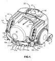
- a robotic floor cleaning device in the form of a robotic vacuum cleaner comprising a chassis 10, two drive wheels 11, a brush bar housing 12, two rechargeable batteries 13 and 14, a cyclonic separator 15 of the type described in European Patent No. EP 042 723, a user interface 16, one (or more) light detectors 17 and various sensors 19 and 27 to 31 which will be more particularly described hereinafter.
- Each drive wheel 11 has an overmoulded ribbed tyre 11A of soft, rubbery plastic which gives a strong grip for driving the cleaner.
- the light detector 17 detects light received from a plurality of compass points around the vacuum cleaner and is more particularly described in our International Patent Application No. WO 00/38027. The details of the operation of the light detector 17 are not essential to the present invention and will not be described any further here.
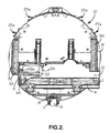
- a cleaner head 12 mounted on the underside of the chassis 10 is a cleaner head 12 which includes a suction opening 2 facing the surface on which the cleaner is supported.
- the suction opening 2 is essentially rectangular and extends across the majority of the width of the cleaner head 12.
- a brush bar 4 is rotatably mounted in the suction opening 2.
- the cut-away portion 2A of the underside of the cleaner head 12 reveals the brush bar motor and drive arrangement within the cleaner head 12.
- a motor 22 is mounted in the cleaner head 12 for driving the brush bar 4 by way of a drive belt 5 extending between a shaft pulley 22A of the motor 22 and the pulley 4A of the brush bar 4.
- the cleaner head 12 is mounted on the chassis 10 in such a way that the cleaner head 12 is able to float on the surface to be cleaned.
- a mounting which includes double articulation between the cleaner head 12 and the chassis 10.
- the double articulation of the connection between the cleaner head 12 and the chassis 10 is more particularly described in our International Patent Application No. WO 00/36965. It allows the cleaner head 12 to move freely in a vertical direction with respect to the chassis 10. This enables the cleaner head 12 to climb over small obstacles such as books, magazines, rug edges etc. Obstacles of up to approximately 25mm in height can be traversed in this way.
- a castor wheel 6 is located at the trailing edge of the chassis 10 and is swivellingly mounted on the chassis by means of a swivel joint 7.
- the castor wheel 6 also includes a ramped portion 8 which provides additional assistance when the cleaner encounters an obstacle and is required to climb over it. In this way, the castor wheel 6 will not become lodged against the obstacle after the drive wheels 11 have moved beyond it.
- the cleaner head 12 is asymmetrically mounted on the chassis 10 so that one side of the cleaner head 12 protrudes beyond the general circumference of the chassis 10. This allows the cleaner to clean up to the edge of a room on the side of the cleaner on which the cleaner head 12 protrudes.
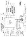
- the circuit shown in Figure 3 comprises the two rechargeable batteries 13 and 14, a battery and motor management system 18, a motor and suction fan unit 9, motors 20 and 21 for driving the left and right hand wheels 11 of the vacuum cleaner, the motor 22 for driving the brush bar 4 of the vacuum cleaner, processing circuitry 23 (which includes a microprocessor and field programmable gate arrays) for a navigation system 34 (see Figure 4), left and right hand sensor interfaces 24, 25 respectively, a user interface board 26 and the light detector 17.
- the navigation system of the robotic vacuum cleaner includes a plurality of infrared sensors 27, a plurality of ultrasonic sensors 19, threshold detectors 30 for detecting the presence of a portable threshold locator (not shown) beyond which the robotic vacuum cleaner may not pass, and one or more pyroelectric detectors 31 for detecting animals and fires.
- the infrared sensors comprise infrared transmitters 27a and infrared receivers 27b and the ultrasonic sensors 19 comprise ultrasonic transmitters 19a and ultrasonic receivers 19b.
- There are four main ultrasonic receivers 19b which face forwards, rearwards and to opposite sides of the robotic vacuum cleaner.
- the signals received by these receivers 19b not only provide information representative of the distance of the robotic vacuum cleaner from a feature of the room or from an object in the room but also the amplitude and width of the received signals vary according to the size and shape of the feature or object and the type of material sensed.
- the battery and motor management system 18 comprises a central processor 33 which receives data from battery monitors (not shown) in the rechargeable batteries 13, 14.
- the processor 33 calculates the charge remaining in the batteries 13, 14 and passes this information on to the processing circuitry 23 of the navigation system 34.
- the central processor 33 typically a Hitachi H8/3334 F microprocessor, is connected to the user interface board 26 and supplies power to the navigation system 34 which includes the processing circuitry 23 and sensors 19 and 27 to 31. It also supplies power to the motors 20, 21 and 22 and the fan unit 9.
- a switch 35 is located on the user interface 16 (see Figure 1).
- the switch 35 interacts directly with the processor 33. Pressing the switch 35 a first time initiates a power down sequence which ultimately sets the processor 33 into an inactive state. Pressing the switch 35 a second time activates the processor 33 which then executes a power-up sequence to enable the robotic vacuum cleaner to be used for cleaning.
- Communication lines 36 between the processor 33 and the navigation system 34 carry data relating to the batteries 13, 14, the fan unit 9 and the power supply 37 in one direction, and control information in the other direction.
- the battery and motor management system 18 includes a power supply unit 37 for providing a regulated supply to the navigation system 34.
- the power supply unit 37 and the motors 20, 21 and 22 and fan unit 9 have current sensors (not shown) and these allow the processor 33 to monitor the current taken by the power supply unit 37 and the motors 20, 21 and 22 and the fan unit 9 and to shut down the relevant power supply if a predefined limit is exceeded.
- Information relating to the current taken by the motors 20 and 21 also provides an indication of the gradient and type of surface over which the vacuum cleaner is moving.
- the outputs from the current sensors are analogue signals. These are conditioned and then converted to digital values for subsequent processing by analogue-to-digital converters integrated into the processor 33 and communicated to the navigation system 34.
- the traction and brush bar motors 20, 21 and 22 require pulse width modulation (PWM) speed control.
- PWM pulse width modulation
- the system therefore has three PWM generators capable of providing 0-100% PWM at >50 kHz with a resolution of 1/128.
- the PWM control of the motors 20, 21 and 22 is carried out in the navigation system 34.
- the particular method of operating and navigating the robotic vacuum cleaner is not a part of the present invention. Suffice it to say that the control and navigation system 34 will drive the cleaner around an area to be cleaned and the various sensors 19 and 27 to 31 will detect any portable threshold locators, obstacles in the room and other room features, such as corners of the room and fireplaces, and the processing circuitry 23 will navigate the robotic vacuum cleaner in order to avoid any such obstacles and to change direction when a comer of the room is reached.
- One particular operating method is described in more detail in our International Patent Application No. WO 00/38025.
- the navigation system therein described includes light detector apparatus.
- the information received from the light detector apparatus in conjunction with information received from obstacle avoidance sensors is used to navigate the cleaner around the room.
- One aspect of the present invention makes use of the ability of the navigation system to locate the cleaner in the room.
- the robotic vacuum cleaner of the present invention is, typically, placed alongside a wall of a room to be cleaned and energised to move forwardly along the wall and so along the edge of the room.
- the various sensors 19, 27-31 will detect any obstacles in the room and other features, such as corners of the room and fireplaces, and the navigation system 34 will navigate the robotic vacuum cleaner in order to avoid any such obstacles and to change direction when a feature of a room is reached.
- the navigation system 34 will store information received from the light detector 17 and also from the ultrasonic receivers 19b in memory 50. It will also store information regarding the direction in which the cleaner is required to turn at each way-point.
- the navigation system 34 will determine that the robotic vacuum cleaner has completed a full traverse around the room.
- the navigation system 34 is programmed to cause the robotic vacuum cleaner to move inwardly by one cleaner-width or substantially one cleaner-width.
- the navigation system 34 will then be able to identify further way-points by comparing the information received from the light detector 17 and the four main ultrasonic receivers 19b with previously stored information and this will enable the robotic vacuum cleaner to navigate itself around the room in a generally inwardly spiral manner whilst simultaneously avoiding any obstacles in its path.
- the robotic vacuum cleaner If the robotic vacuum cleaner is initially placed in the middle of the room, it will travel until it finds a wall or obstacle. If it finds a wall it will then follow the path described above. If it finds a feature (such as a central fireplace) or an obstacle in the centre of the room, it will complete a circuit around that feature or obstacle and then follow a generally outwardly spiral path, still avoiding obstacles as and when necessary.
- a feature such as a central fireplace
- the vacuum cleaner starts from position A shown in Figure 5 and moves along the edge of the room adjacent the first wall W1 in a clockwise direction, at position B it will sense the presence of the second wall W2 in front of it and will turn 90° to the right. It will already know from the sensors that there is a wall W2 on its left hand side. The cleaner will then continue until it reaches position C when it will sense the presence of the third wall W3 in front and will turn 90° to the right again to run along the side of the third wall W3.
- the cleaner is programmed to keep one side close to the nearest wall or obstacle or close to the most recently covered circuit of the room.
- Information representative of the level of light detected at each way-point will be stored in memory together with information from the four main ultrasonic receivers 19b.
- the cleaner returns to similar way-points, e.g. way-points C',C"; D',D"; E',E”; etc.
- information on the two similar points will be associated with one another in memory in order to build up an information strand. This will tell the cleaner that it has returned to a known point and will also tell the cleaner when the floor of the room, apart from areas occupied by obstacles, has been cleaned.
- reference numeral 40 represents a circular rug having tassels around its edge.
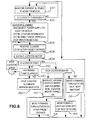
- the microprocessor regularly monitors current supplied to the brushbar motor (step 100). Whilst making its second traverse around the room, the cleaner will encounter the tasselled edge of rug 40 at point 41. If the tassels are sufficiently long there is a risk of entanglement in the brush bar 4. If the tassels become entangled with the brush bar 4 the following disentanglement procedure takes place.
- the microprocessor 33 at step 102, will detect an increase in current supplied to the brush bar motor 22 indicative of a significant reduction in rotational speed of the brush bar 4.
- the microprocessor 33 then sends a signal to the navigation system 34 which is programmed to disconnect the power to the brush bar motor 22 (step 104).
- the navigation system 34 will also identify point 41 as a "danger" way-point which is stored in the memory 50 together with information from the ultrasonic receivers 19b. The direction of approach to the point 41 is also stored in the memory 50.
- the navigation system 34 is programmed to stop the drive motors 20 and 21 and subsequently to drive them in reverse (step 106).
- the navigation system 34 monitors the sensors 19b located either at the front or at the rear of the cleaner to detect a change in the distance of the cleaner from wall W3 or W1.
- X can be 20cms, or a distance comparable with the length of the cleaner.
- the navigation system 34 will stop the drive motors 20, 21 to bring the cleaner to a standstill. Subsequently, the navigation system 34 will re-start the motor 22 (step 108) and will assume that the brush bar is disentangled unless it receives a signal from the microprocessor 33 that the brush bar is still jammed or has again become jammed (step 110).
- the navigation system 34 is programmed to then proceed in one of several alternative modes.
- the navigation system 34 will stop the brush bar 4 again (step 112) having regard for the "danger" way-point memorised for this location, but will otherwise continue to navigate the cleaner along the line D' - E' as shown in Figure 5 until way-point E' is reached (step 116). At this point the brush bar 4 will be started again and will continue to rotate for the remainder of the cleaning programme unless interrupted by another entanglement e.g. at point 43. Thus under this mode the remaining portion of line D' - E' represents a cleaning track during which the suction fan 9 is operational but the brush bar motor 22 is not.
- the navigation system 34 is programmed to guide and drive the cleaner forward along the line D'- E' with the brush bar 4 switched off to a point 44 which lies a predetermined distance Y beyond the point 41 (step 114).
- the distance between points 42 and 44 is greater than the distance X by which the cleaner was moved backwards from point 41.
- the brush bar motor 22 is then switched on again to recommence rotation of the brush bar 4 when it is hoped that the cleaner is clear of the rug tassels.
- This distance is measured by the ultrasonic sensors 19 in the same way as distance X was measured.
- the forward distance could be twice the backwards distance X.
- the cleaner would then continue under the control of the navigation system 34 according to Figure 5 along the remainder of line D' - E'. In this mode, only a relatively short distance (e.g. 40cms) would be cleaned without the brush bar 4 turning.
- the navigation system 34 is programmed to continue cleaning the floor of the room according to the spiral pattern illustrated in Figure 5 but with the brush bar motor 22 switched off for the remainder of the cleaning operation (step 118).
- the navigation system 34 is programmed to proceed according to the spiral pattern illustrated in Figure 5 but regarding the point 41 as an obstacle over which the cleaner may not pass (step 119).
- the navigation system 34 will ensure that the cleaner does not pass directly over point 41 but navigates around it. It is, of course, possible that the new path of the cleaner will take it over another part of the edge of the tasselled rug 40 and a further danger way-point will be identified. This further way-point will be dealt with in the same way as the initial way-point.
- the room shown in Figure 5 has a simple layout and that, in reality, the room would contain furniture and other objects which the cleaner would navigate around. Thus the cleaner may be required to travel over the location 41 at which the brush bar 4 became jammed at another point in the cleaning operation.
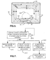
- the flow diagram of Figure 7 shows how the cleaner operates.
- the navigation system 34 compares the current location with the stored list of locations where the brush bar has previously jammed. If the navigation system determines that the cleaner is close to one of stored locations, it can take one of several actions in an attempt to prevent a further brush bar jam.
- the navigation system operates to navigate the cleaner around the location where the jam occurred.
- the brush bar motor 22 may be switched off for a period of time immediately before and after the location 41 is overrun on each and every occasion that this occurs.
- the cleaner compares the current direction of approach to the location where the jam occurred with the stored direction of approach and operates so to allow the cleaner to overrun location 41 as long as the direction of approach thereto is not the same as that when the brush bar 4 previously became jammed. Where the cleaner navigates around the room in a controlled manner with a regular pattern, such as the spiral pattern shown in Fig. 5, the cleaner will return to a similar position in the room on a subsequent lap of the room; e.g. positions 41 and 43.
- the comparison step 200 allows for a difference in position of at least the step distance between laps.
- the brush bar 4 of the cleaner of Figures 1 to 5 is driven at around 3000rpm ⁇ 500rpm (dependent upon the surface being cleaned) through a 2:1 reduction drive from the motor 22 which runs therefore at twice the speed of the brush bar 4.
- the drive coupling is an elastic belt and, when the motor is not energised, the brush bar 4 free wheels quite easily.
- the brush bar motor 22 normally draws about 0.6amps at 36 volts. This produces a motor torque of 40mNm, around 80mNm at the brush bar 4. If the current increases above 1.00amp the navigation system 34 will trigger the entanglement procedure discussed above.
- the drive motors 20 and 21 are coupled to the respective wheels 11 by reduction gearing (not shown) and provide a torque of 360mNm. It is to be noted that the dirty air inlet 2 lies behind the drive wheels 11 in normal forward motion (towards the bottom left corner in Figure 1). During rearward motion of the cleaner when disentangling a carpet tassel, the wheel grip will be increased due to the direction of tension force in any tassel that has been caught in the brush bar 4, thereby enhancing the tractive force available to move the cleaner backwards and thereby to disentangle the tassel.
- the fact that the brush bar has jammed can be detected using means other than a current sensor as described above. Any sensor which will produce a signal to the microprocessor 33 when the brush bar slows to a stop or a virtual stop will achieve the same effect as the current sensing device mentioned above.
- infrared sensors arranged in the vicinity of the brush bar can be used in a known manner to sense the rotational speed of the brush bar and a signal can be sent to the microprocessor when the speed falls below a preset value.
- the control system is described here as storing sensor information such as light sensor and ultrasonic sensor measurements which are indicative of a location in a room, actual location information could also be stored. Other variations and modifications to the specific features of the embodiment described above will be apparent to a skilled reader.
Landscapes
- Engineering & Computer Science (AREA)
- Mechanical Engineering (AREA)
- Radar, Positioning & Navigation (AREA)
- Physics & Mathematics (AREA)
- Remote Sensing (AREA)
- General Physics & Mathematics (AREA)
- Acoustics & Sound (AREA)
- Aviation & Aerospace Engineering (AREA)
- Robotics (AREA)
- Automation & Control Theory (AREA)
- Electric Vacuum Cleaner (AREA)
- Electric Suction Cleaners (AREA)
- Control Of Position, Course, Altitude, Or Attitude Of Moving Bodies (AREA)
- Nozzles For Electric Vacuum Cleaners (AREA)
- Vehicle Cleaning, Maintenance, Repair, Refitting, And Outriggers (AREA)
- Spinning Or Twisting Of Yarns (AREA)
- Cleaning In General (AREA)
Applications Claiming Priority (3)
| Application Number | Priority Date | Filing Date | Title |
|---|---|---|---|
| GB9917232 | 1999-07-23 | ||
| GBGB9917232.2A GB9917232D0 (en) | 1999-07-23 | 1999-07-23 | Method of operating a floor cleaning device |
| PCT/GB2000/002815 WO2001006904A1 (en) | 1999-07-23 | 2000-07-20 | Robotic floor cleaning device |
Publications (2)
| Publication Number | Publication Date |
|---|---|
| EP1198192A1 EP1198192A1 (en) | 2002-04-24 |
| EP1198192B1 true EP1198192B1 (en) | 2003-04-16 |
Family
ID=10857753
Family Applications (1)
| Application Number | Title | Priority Date | Filing Date |
|---|---|---|---|
| EP00946185A Expired - Lifetime EP1198192B1 (en) | 1999-07-23 | 2000-07-20 | Robotic floor cleaning device |
Country Status (9)
| Country | Link |
|---|---|
| US (1) | US6605156B1 (enExample) |
| EP (1) | EP1198192B1 (enExample) |
| JP (1) | JP4426145B2 (enExample) |
| AT (1) | ATE237275T1 (enExample) |
| AU (1) | AU761745B2 (enExample) |
| DE (1) | DE60002209T2 (enExample) |
| ES (1) | ES2197105T3 (enExample) |
| GB (1) | GB9917232D0 (enExample) |
| WO (1) | WO2001006904A1 (enExample) |
Cited By (1)
| Publication number | Priority date | Publication date | Assignee | Title |
|---|---|---|---|---|
| US11324372B2 (en) | 2017-10-20 | 2022-05-10 | Techtronic Floor Care Technology Limited | Vacuum cleaner and method of controlling a motor for a brush of the vacuum cleaner |
Families Citing this family (148)
| Publication number | Priority date | Publication date | Assignee | Title |
|---|---|---|---|---|
| US8412377B2 (en) * | 2000-01-24 | 2013-04-02 | Irobot Corporation | Obstacle following sensor scheme for a mobile robot |
| US7155308B2 (en) | 2000-01-24 | 2006-12-26 | Irobot Corporation | Robot obstacle detection system |
| US8788092B2 (en) | 2000-01-24 | 2014-07-22 | Irobot Corporation | Obstacle following sensor scheme for a mobile robot |
| US6956348B2 (en) | 2004-01-28 | 2005-10-18 | Irobot Corporation | Debris sensor for cleaning apparatus |
| DE10020503A1 (de) * | 2000-04-26 | 2001-10-31 | Bsh Bosch Siemens Hausgeraete | Vorrichtung zur Durchführung von Arbeiten an einer Fläche |
| US7571511B2 (en) | 2002-01-03 | 2009-08-11 | Irobot Corporation | Autonomous floor-cleaning robot |
| US6883201B2 (en) | 2002-01-03 | 2005-04-26 | Irobot Corporation | Autonomous floor-cleaning robot |
| US6690134B1 (en) | 2001-01-24 | 2004-02-10 | Irobot Corporation | Method and system for robot localization and confinement |
| EP2386924B1 (en) | 2001-06-12 | 2019-05-29 | iRobot Corporation | Mobile robot |
| US8396592B2 (en) | 2001-06-12 | 2013-03-12 | Irobot Corporation | Method and system for multi-mode coverage for an autonomous robot |
| US7663333B2 (en) | 2001-06-12 | 2010-02-16 | Irobot Corporation | Method and system for multi-mode coverage for an autonomous robot |
| IL145680A0 (en) | 2001-09-26 | 2002-06-30 | Friendly Robotics Ltd | Robotic vacuum cleaner |
| AU2002341358A1 (en) | 2001-09-26 | 2003-04-07 | Friendly Robotics Ltd. | Robotic vacuum cleaner |
| US9128486B2 (en) | 2002-01-24 | 2015-09-08 | Irobot Corporation | Navigational control system for a robotic device |
| US8386081B2 (en) | 2002-09-13 | 2013-02-26 | Irobot Corporation | Navigational control system for a robotic device |
| US8428778B2 (en) | 2002-09-13 | 2013-04-23 | Irobot Corporation | Navigational control system for a robotic device |
| JP4838978B2 (ja) * | 2002-12-16 | 2011-12-14 | アイロボット コーポレイション | 自律的床清掃ロボット |
| US7805220B2 (en) | 2003-03-14 | 2010-09-28 | Sharper Image Acquisition Llc | Robot vacuum with internal mapping system |
| US20050010331A1 (en) * | 2003-03-14 | 2005-01-13 | Taylor Charles E. | Robot vacuum with floor type modes |
| US20040244138A1 (en) * | 2003-03-14 | 2004-12-09 | Taylor Charles E. | Robot vacuum |
| US20040200505A1 (en) * | 2003-03-14 | 2004-10-14 | Taylor Charles E. | Robot vac with retractable power cord |
| US7801645B2 (en) * | 2003-03-14 | 2010-09-21 | Sharper Image Acquisition Llc | Robotic vacuum cleaner with edge and object detection system |
| USD524495S1 (en) * | 2003-06-24 | 2006-07-04 | Aktiebolaget Electrolux | Robot vacuum cleaner |
| KR100528297B1 (ko) | 2003-07-31 | 2005-11-15 | 삼성전자주식회사 | 로봇 청소기의 제어시스템 |
| US20050055792A1 (en) * | 2003-09-15 | 2005-03-17 | David Kisela | Autonomous vacuum cleaner |
| USD503251S1 (en) * | 2003-10-03 | 2005-03-22 | Sharper Image Corporation | Vacuum cleaner |
| KR20050072300A (ko) * | 2004-01-06 | 2005-07-11 | 삼성전자주식회사 | 청소로봇 및 그 제어방법 |
| US7332890B2 (en) | 2004-01-21 | 2008-02-19 | Irobot Corporation | Autonomous robot auto-docking and energy management systems and methods |
| US20050273967A1 (en) * | 2004-03-11 | 2005-12-15 | Taylor Charles E | Robot vacuum with boundary cones |
| WO2005098476A1 (en) | 2004-03-29 | 2005-10-20 | Evolution Robotics, Inc. | Method and apparatus for position estimation using reflected light sources |
| US6856113B1 (en) | 2004-05-12 | 2005-02-15 | Cube Investments Limited | Central vacuum cleaning system motor control circuit mounting post, mounting configuration, and mounting methods |
| KR100544480B1 (ko) * | 2004-05-12 | 2006-01-24 | 삼성광주전자 주식회사 | 로봇 청소기 |
| WO2006002385A1 (en) | 2004-06-24 | 2006-01-05 | Irobot Corporation | Programming and diagnostic tool for a mobile robot |
| US7214037B2 (en) | 2004-06-28 | 2007-05-08 | Honeywell International, Inc. | Retention of ball bearing cartridge for turbomachinery |
| US7706917B1 (en) | 2004-07-07 | 2010-04-27 | Irobot Corporation | Celestial navigation system for an autonomous robot |
| US8972052B2 (en) | 2004-07-07 | 2015-03-03 | Irobot Corporation | Celestial navigation system for an autonomous vehicle |
| KR20060015082A (ko) * | 2004-08-13 | 2006-02-16 | 엘지전자 주식회사 | 로봇 청소기의 브러시 동력전달장치 |
| US7620476B2 (en) | 2005-02-18 | 2009-11-17 | Irobot Corporation | Autonomous surface cleaning robot for dry cleaning |
| AU2006214016B2 (en) | 2005-02-18 | 2011-11-10 | Irobot Corporation | Autonomous surface cleaning robot for wet and dry cleaning |
| US8392021B2 (en) | 2005-02-18 | 2013-03-05 | Irobot Corporation | Autonomous surface cleaning robot for wet cleaning |
| US7389156B2 (en) | 2005-02-18 | 2008-06-17 | Irobot Corporation | Autonomous surface cleaning robot for wet and dry cleaning |
| US8930023B2 (en) | 2009-11-06 | 2015-01-06 | Irobot Corporation | Localization by learning of wave-signal distributions |
| DE102005027183A1 (de) * | 2005-06-07 | 2006-12-14 | Alfred Kärcher Gmbh & Co. Kg | Fahrbare Bodenreinigungsmaschine |
| EP1928286B1 (en) * | 2005-07-20 | 2012-12-05 | Optimus Licensing AG | Robotic floor cleaning with sterile, disposable cartridges |
| JP4972100B2 (ja) | 2005-12-02 | 2012-07-11 | アイロボット コーポレイション | モジュール式ロボット |
| EP2466411B1 (en) | 2005-12-02 | 2018-10-17 | iRobot Corporation | Robot system |
| DE602006009148D1 (de) * | 2005-12-02 | 2009-10-22 | Irobot Corp | Abdeckungsrobotermobilität |
| EP2816434A3 (en) | 2005-12-02 | 2015-01-28 | iRobot Corporation | Autonomous coverage robot |
| EP2267568B1 (en) * | 2005-12-02 | 2014-09-24 | iRobot Corporation | Autonomous coverage robot navigation system |
| US7441298B2 (en) | 2005-12-02 | 2008-10-28 | Irobot Corporation | Coverage robot mobility |
| RU2423905C2 (ru) * | 2006-02-13 | 2011-07-20 | Конинклейке Филипс Электроникс Н.В. | Робот-пылесос |
| ES2707155T3 (es) | 2006-03-17 | 2019-04-02 | Irobot Corp | Confinamiento de robot |
| EP2394553B1 (en) | 2006-05-19 | 2016-04-20 | iRobot Corporation | Removing debris from cleaning robots |
| US8417383B2 (en) | 2006-05-31 | 2013-04-09 | Irobot Corporation | Detecting robot stasis |
| US20080092324A1 (en) * | 2006-10-18 | 2008-04-24 | Guten Electronics Industrial Co., Ltd. | Dust-collecting auxiliary device for vacuum cleaner |
| KR100824315B1 (ko) | 2007-02-23 | 2008-04-22 | 주식회사 유진로봇 | 주행로봇 |
| US8239992B2 (en) | 2007-05-09 | 2012-08-14 | Irobot Corporation | Compact autonomous coverage robot |
| WO2009011542A1 (en) * | 2007-07-18 | 2009-01-22 | Lg Electronics Inc. | Mobile robot and controlling method thereof |
| US9820626B2 (en) | 2008-03-17 | 2017-11-21 | Aktiebolaget Electrolux | Actuator mechanism for a brushroll cleaner |
| WO2013060365A1 (en) | 2011-10-26 | 2013-05-02 | Aktiebolaget Electrolux | Cleaning nozzle for a vacuum cleaner |
| CN103549922B (zh) | 2008-03-17 | 2016-09-14 | 伊莱克斯家用产品有限公司 | 具有清洁部件的搅拌器 |
| US10117553B2 (en) | 2008-03-17 | 2018-11-06 | Aktiebolaget Electrolux | Cleaning nozzle for a vacuum cleaner |
| US9295362B2 (en) * | 2008-03-17 | 2016-03-29 | Aktiebolaget Electrolux | Vacuum cleaner agitator cleaner with power control |
| US8136193B2 (en) * | 2008-07-15 | 2012-03-20 | Federal Signal Corporation | Side broom having memory recall and method for performing the same |
| DE102009018338A1 (de) * | 2009-04-23 | 2010-11-04 | Miele & Cie. Kg | Verfahren zum Betrieb eines Vorsatzgeräts für einen Staubsauger und korrespondierendes Vorsatzgerät |
| US8364309B1 (en) * | 2009-07-14 | 2013-01-29 | Bailey Bendrix L | User-assisted robot navigation system |
| EP2536322B1 (en) | 2010-02-16 | 2017-04-05 | iRobot Corporation | Vacuum brush |
| BR112013004501A2 (pt) * | 2010-09-01 | 2016-06-07 | Techtronic Floor Care Tech Ltd | controle de fluxo de uma máquina extratora de limpeza |
| KR101752190B1 (ko) * | 2010-11-24 | 2017-06-30 | 삼성전자주식회사 | 로봇청소기 및 그 제어방법 |
| JP5832553B2 (ja) | 2010-12-30 | 2015-12-16 | アイロボット コーポレイション | カバレッジロボットナビゲーション |
| GB2494446B (en) * | 2011-09-09 | 2013-12-18 | Dyson Technology Ltd | Autonomous cleaning appliance |
| GB2494447B (en) * | 2011-09-09 | 2014-02-26 | Dyson Technology Ltd | Autonomous surface treating appliance |
| GB2494443B (en) * | 2011-09-09 | 2013-08-07 | Dyson Technology Ltd | Autonomous surface treating appliance |
| CN104080384B (zh) | 2012-02-02 | 2016-10-12 | 伊莱克斯公司 | 用于真空吸尘器吸嘴的清洁装置 |
| US20130291319A1 (en) * | 2012-05-07 | 2013-11-07 | Joseph Y. Ko | Cleaning structure for autonomous moving floor sweeping machines |
| ES2610755T3 (es) | 2012-08-27 | 2017-05-03 | Aktiebolaget Electrolux | Sistema de posicionamiento de un robot |
| US8855914B1 (en) | 2012-08-31 | 2014-10-07 | Neato Robotics, Inc. | Method and apparatus for traversing corners of a floored area with a robotic surface treatment apparatus |
| AU2013317738B2 (en) | 2012-09-21 | 2015-05-07 | Irobot Corporation | Proximity sensing on mobile robots |
| JP6272899B2 (ja) | 2012-12-21 | 2018-01-31 | アクティエボラゲット エレクトロラックス | 掃除機の回転可能部材のためのクリーニング装置、掃除機ノズル、掃除機、および掃除ユニット |
| US9877629B2 (en) | 2013-02-08 | 2018-01-30 | Techtronic Industries Co. Ltd. | Battery-powered cordless cleaning system |
| US9072416B2 (en) | 2013-03-15 | 2015-07-07 | Aktiebolaget Electrolux | Vacuum cleaner agitator cleaner with brushroll lifting mechanism |
| US9326654B2 (en) | 2013-03-15 | 2016-05-03 | Irobot Corporation | Roller brush for surface cleaning robots |
| KR102024358B1 (ko) * | 2013-03-15 | 2019-09-23 | 에이비 엘렉트로룩스 | 파워 콘트롤을 갖는 진공 청소기 교반기의 청소기 |
| CN110448222A (zh) | 2013-04-15 | 2019-11-15 | 伊莱克斯公司 | 机器人真空吸尘器 |
| JP6198234B2 (ja) | 2013-04-15 | 2017-09-20 | アクティエボラゲット エレクトロラックス | 突出サイドブラシを備えたロボット真空掃除機 |
| US9775477B2 (en) | 2013-05-02 | 2017-10-03 | Aktiebolaget Electrolux | Cleaning nozzle for a vacuum cleaner |
| CN103622641B (zh) * | 2013-11-04 | 2015-12-02 | 深圳市朗科智能电气股份有限公司 | 一种利用吸尘器自动识别地毯材料的方法及装置 |
| CN206950128U (zh) | 2013-12-18 | 2018-02-02 | 艾罗伯特公司 | 自主移动机器人 |
| WO2015090399A1 (en) | 2013-12-19 | 2015-06-25 | Aktiebolaget Electrolux | Robotic cleaning device and method for landmark recognition |
| US10149589B2 (en) | 2013-12-19 | 2018-12-11 | Aktiebolaget Electrolux | Sensing climb of obstacle of a robotic cleaning device |
| ES2675786T3 (es) | 2013-12-19 | 2018-07-12 | Aktiebolaget Electrolux | Control de velocidad adaptativo de cepillo lateral rotatorio |
| US10209080B2 (en) | 2013-12-19 | 2019-02-19 | Aktiebolaget Electrolux | Robotic cleaning device |
| US9946263B2 (en) | 2013-12-19 | 2018-04-17 | Aktiebolaget Electrolux | Prioritizing cleaning areas |
| EP3084538B1 (en) | 2013-12-19 | 2017-11-01 | Aktiebolaget Electrolux | Robotic cleaning device with perimeter recording function |
| JP6638988B2 (ja) | 2013-12-19 | 2020-02-05 | アクチエボラゲット エレクトロルックス | サイドブラシを有し、渦巻きパターンで動くロボットバキュームクリーナ |
| WO2015090439A1 (en) | 2013-12-20 | 2015-06-25 | Aktiebolaget Electrolux | Dust container |
| WO2015153109A1 (en) | 2014-03-31 | 2015-10-08 | Irobot Corporation | Autonomous mobile robot |
| US10518416B2 (en) | 2014-07-10 | 2019-12-31 | Aktiebolaget Electrolux | Method for detecting a measurement error in a robotic cleaning device |
| WO2016037636A1 (en) | 2014-09-08 | 2016-03-17 | Aktiebolaget Electrolux | Robotic vacuum cleaner |
| KR102271785B1 (ko) | 2014-09-08 | 2021-06-30 | 에이비 엘렉트로룩스 | 로봇 진공 청소기 |
| US9510505B2 (en) | 2014-10-10 | 2016-12-06 | Irobot Corporation | Autonomous robot localization |
| US9516806B2 (en) | 2014-10-10 | 2016-12-13 | Irobot Corporation | Robotic lawn mowing boundary determination |
| EP3230814B1 (en) | 2014-12-10 | 2021-02-17 | Aktiebolaget Electrolux | Using laser sensor for floor type detection |
| CN114668335A (zh) | 2014-12-12 | 2022-06-28 | 伊莱克斯公司 | 侧刷和机器人吸尘器 |
| US9420741B2 (en) | 2014-12-15 | 2016-08-23 | Irobot Corporation | Robot lawnmower mapping |
| KR102326401B1 (ko) * | 2014-12-16 | 2021-11-16 | 에이비 엘렉트로룩스 | 로봇 청소 장치를 위한 청소 방법 |
| WO2016095965A2 (en) * | 2014-12-16 | 2016-06-23 | Aktiebolaget Electrolux | Experience-based roadmap for a robotic cleaning device |
| US9538702B2 (en) | 2014-12-22 | 2017-01-10 | Irobot Corporation | Robotic mowing of separated lawn areas |
| KR102343513B1 (ko) | 2015-04-17 | 2021-12-28 | 에이비 엘렉트로룩스 | 로봇 청소 장치 및 로봇 청소 장치의 제어 방법 |
| DE102015109775B3 (de) | 2015-06-18 | 2016-09-22 | RobArt GmbH | Optischer Triangulationssensor zur Entfernungsmessung |
| US11115798B2 (en) | 2015-07-23 | 2021-09-07 | Irobot Corporation | Pairing a beacon with a mobile robot |
| US10034421B2 (en) | 2015-07-24 | 2018-07-31 | Irobot Corporation | Controlling robotic lawnmowers |
| KR102445064B1 (ko) | 2015-09-03 | 2022-09-19 | 에이비 엘렉트로룩스 | 로봇 청소 장치의 시스템 |
| DE102015114883A1 (de) | 2015-09-04 | 2017-03-09 | RobArt GmbH | Identifizierung und Lokalisierung einer Basisstation eines autonomen mobilen Roboters |
| KR102315953B1 (ko) * | 2015-09-17 | 2021-10-22 | 삼성전자주식회사 | 청소 로봇 및 그 제어 방법 |
| DE102015119501A1 (de) | 2015-11-11 | 2017-05-11 | RobArt GmbH | Unterteilung von Karten für die Roboternavigation |
| DE102015119865B4 (de) | 2015-11-17 | 2023-12-21 | RobArt GmbH | Robotergestützte Bearbeitung einer Oberfläche mittels eines Roboters |
| DE102015121666B3 (de) | 2015-12-11 | 2017-05-24 | RobArt GmbH | Fernsteuerung eines mobilen, autonomen Roboters |
| US10021830B2 (en) | 2016-02-02 | 2018-07-17 | Irobot Corporation | Blade assembly for a grass cutting mobile robot |
| DE102016102644A1 (de) | 2016-02-15 | 2017-08-17 | RobArt GmbH | Verfahren zur Steuerung eines autonomen mobilen Roboters |
| US10459063B2 (en) | 2016-02-16 | 2019-10-29 | Irobot Corporation | Ranging and angle of arrival antenna system for a mobile robot |
| EP3430424B1 (en) | 2016-03-15 | 2021-07-21 | Aktiebolaget Electrolux | Robotic cleaning device and a method at the robotic cleaning device of performing cliff detection |
| CN109068908B (zh) | 2016-05-11 | 2021-05-11 | 伊莱克斯公司 | 机器人清洁设备 |
| US12140965B2 (en) | 2016-08-05 | 2024-11-12 | Rotrade Asset Management Gmbh | Method for controlling an autonomous mobile robot |
| US10278558B1 (en) | 2016-10-05 | 2019-05-07 | Al Incorporated | Brush with pressure sensor |
| US10602899B1 (en) | 2016-10-05 | 2020-03-31 | AI Incorporated | Brush with pressure sensor |
| US10524627B1 (en) | 2016-10-05 | 2020-01-07 | Al Incorporated | Method for automatically removing obstructions from robotic floor-cleaning devices |
| JP7054604B2 (ja) * | 2016-10-11 | 2022-04-14 | 日立グローバルライフソリューションズ株式会社 | 自律走行型電気掃除機 |
| JP7033821B2 (ja) * | 2016-12-26 | 2022-03-11 | アイロボット・コーポレーション | デブリセンサを備えた清浄装置 |
| US10375880B2 (en) | 2016-12-30 | 2019-08-13 | Irobot Corporation | Robot lawn mower bumper system |
| KR101759517B1 (ko) | 2017-01-17 | 2017-07-31 | (주)티엔에스 | 골프 클럽헤드 세척장치 |
| CN110709790A (zh) | 2017-03-02 | 2020-01-17 | 罗博艾特有限责任公司 | 用于控制自主移动机器人的方法 |
| DE102017109219A1 (de) | 2017-04-28 | 2018-10-31 | RobArt GmbH | Verfahren für die Roboternavigation |
| JP7243967B2 (ja) | 2017-06-02 | 2023-03-22 | アクチエボラゲット エレクトロルックス | ロボット清掃デバイスの前方の表面のレベル差を検出する方法 |
| WO2019013989A1 (en) | 2017-07-14 | 2019-01-17 | Irobot Corporation | BLADE ASSEMBLY FOR MOBILE GRASS CUTTING ROBOT |
| KR20200058400A (ko) | 2017-09-26 | 2020-05-27 | 에이비 엘렉트로룩스 | 로봇 청소 장치의 이동 제어 |
| KR20200001159U (ko) * | 2017-10-25 | 2020-06-03 | 비쎌 인코포레이티드 | 다중 컨트롤러를 갖는 자율 표면 청소 장치 |
| JP2019084096A (ja) * | 2017-11-08 | 2019-06-06 | 日立アプライアンス株式会社 | 自律走行型電気掃除機 |
| JP6985923B2 (ja) * | 2017-12-20 | 2021-12-22 | ヤフー株式会社 | 情報処理装置、情報処理方法および情報処理プログラム |
| EP3740109A1 (en) | 2018-01-17 | 2020-11-25 | Techtronic Floor Care Technology Limited | System and method for operating a cleaning system based on a surface to be cleaned |
| CN209966277U (zh) * | 2018-02-05 | 2020-01-21 | 科沃斯机器人股份有限公司 | 自移动机器人 |
| JP6531211B2 (ja) * | 2018-10-25 | 2019-06-12 | 日立グローバルライフソリューションズ株式会社 | 自律走行型電気掃除機 |
| US11109727B2 (en) | 2019-02-28 | 2021-09-07 | Irobot Corporation | Cleaning rollers for cleaning robots |
| US12239267B2 (en) | 2019-07-02 | 2025-03-04 | Mark Jeffery Giarritta | Four-direction scrubbing carpet shampooer |
| US11327483B2 (en) * | 2019-09-30 | 2022-05-10 | Irobot Corporation | Image capture devices for autonomous mobile robots and related systems and methods |
| US20240245190A1 (en) | 2023-01-19 | 2024-07-25 | Sharkninja Operating Llc | Identification of hair care appliance attachments |
| KR20250154586A (ko) | 2023-01-19 | 2025-10-28 | 샤크닌자 오퍼레이팅 엘엘씨 | 전력 공급 부착물을 갖는 헤어 케어 기기 |
| JP7777165B2 (ja) * | 2024-03-26 | 2025-11-27 | ソフトバンクロボティクス株式会社 | 自走式清掃装置およびその制御方法、制御プログラム |
Family Cites Families (7)
| Publication number | Priority date | Publication date | Assignee | Title |
|---|---|---|---|---|
| DE3171655D1 (en) | 1980-03-26 | 1985-09-12 | James Dyson | Vacuum cleaning appliances |
| FR2648071B1 (fr) * | 1989-06-07 | 1995-05-19 | Onet | Procede et appareil autonomes de nettoyage automatique de sol par execution de missions programmees |
| US5109566A (en) * | 1990-06-28 | 1992-05-05 | Matsushita Electric Industrial Co., Ltd. | Self-running cleaning apparatus |
| GB9220382D0 (en) * | 1992-09-26 | 1992-11-11 | Hamilton Robin | Compacting apparatus |
| US5634237A (en) | 1995-03-29 | 1997-06-03 | Paranjpe; Ajit P. | Self-guided, self-propelled, convertible cleaning apparatus |
| SE506372C2 (sv) * | 1996-04-30 | 1997-12-08 | Electrolux Ab | Självgående anordning |
| US6389329B1 (en) * | 1997-11-27 | 2002-05-14 | Andre Colens | Mobile robots and their control system |
-
1999
- 1999-07-23 GB GBGB9917232.2A patent/GB9917232D0/en not_active Ceased
-
2000
- 2000-07-20 EP EP00946185A patent/EP1198192B1/en not_active Expired - Lifetime
- 2000-07-20 WO PCT/GB2000/002815 patent/WO2001006904A1/en not_active Ceased
- 2000-07-20 US US10/031,604 patent/US6605156B1/en not_active Expired - Lifetime
- 2000-07-20 AT AT00946185T patent/ATE237275T1/de not_active IP Right Cessation
- 2000-07-20 ES ES00946185T patent/ES2197105T3/es not_active Expired - Lifetime
- 2000-07-20 DE DE60002209T patent/DE60002209T2/de not_active Expired - Fee Related
- 2000-07-20 JP JP2001511803A patent/JP4426145B2/ja not_active Expired - Lifetime
- 2000-07-20 AU AU60058/00A patent/AU761745B2/en not_active Ceased
Cited By (1)
| Publication number | Priority date | Publication date | Assignee | Title |
|---|---|---|---|---|
| US11324372B2 (en) | 2017-10-20 | 2022-05-10 | Techtronic Floor Care Technology Limited | Vacuum cleaner and method of controlling a motor for a brush of the vacuum cleaner |
Also Published As
| Publication number | Publication date |
|---|---|
| ATE237275T1 (de) | 2003-05-15 |
| AU6005800A (en) | 2001-02-13 |
| WO2001006904A1 (en) | 2001-02-01 |
| JP2003505127A (ja) | 2003-02-12 |
| EP1198192A1 (en) | 2002-04-24 |
| AU761745B2 (en) | 2003-06-12 |
| JP4426145B2 (ja) | 2010-03-03 |
| DE60002209T2 (de) | 2004-03-04 |
| DE60002209D1 (de) | 2003-05-22 |
| ES2197105T3 (es) | 2004-01-01 |
| US6605156B1 (en) | 2003-08-12 |
| GB9917232D0 (en) | 1999-09-22 |
Similar Documents
| Publication | Publication Date | Title |
|---|---|---|
| EP1198192B1 (en) | Robotic floor cleaning device | |
| CN101384973B (zh) | 机器人真空清洁 | |
| JP5560333B2 (ja) | 自律型カバレッジロボット | |
| JP6405136B2 (ja) | 自律型カバレッジロボット | |
| US7237298B2 (en) | Sensors and associated methods for controlling a vacuum cleaner | |
| US8978196B2 (en) | Coverage robot mobility | |
| US9480381B2 (en) | Compact autonomous coverage robot | |
| US20040200505A1 (en) | Robot vac with retractable power cord | |
| EP1360922A2 (en) | Robotic vacuum cleaner with removable portable vacuum head and semi-automated environment mapping | |
| JP2006516771A (ja) | 自律機械 | |
| AU2014202140A1 (en) | Autonomous coverage robots | |
| HK1059719B (en) | Robotic vacuum cleaner with removable portable vacuum head and semi-automated environment mapping |
Legal Events
| Date | Code | Title | Description |
|---|---|---|---|
| PUAI | Public reference made under article 153(3) epc to a published international application that has entered the european phase |
Free format text: ORIGINAL CODE: 0009012 |
|
| 17P | Request for examination filed |
Effective date: 20011113 |
|
| AK | Designated contracting states |
Kind code of ref document: A1 Designated state(s): AT BE CH CY DE DK ES FI FR GB GR IE IT LI LU MC NL PT SE |
|
| AX | Request for extension of the european patent |
Free format text: AL;LT;LV;MK;RO;SI |
|
| GRAG | Despatch of communication of intention to grant |
Free format text: ORIGINAL CODE: EPIDOS AGRA |
|
| 17Q | First examination report despatched |
Effective date: 20020624 |
|
| GRAG | Despatch of communication of intention to grant |
Free format text: ORIGINAL CODE: EPIDOS AGRA |
|
| GRAH | Despatch of communication of intention to grant a patent |
Free format text: ORIGINAL CODE: EPIDOS IGRA |
|
| GRAH | Despatch of communication of intention to grant a patent |
Free format text: ORIGINAL CODE: EPIDOS IGRA |
|
| GRAA | (expected) grant |
Free format text: ORIGINAL CODE: 0009210 |
|
| AK | Designated contracting states |
Designated state(s): AT BE CH CY DE DK ES FI FR GB GR IE IT LI LU MC NL PT SE |
|
| PG25 | Lapsed in a contracting state [announced via postgrant information from national office to epo] |
Ref country code: BE Free format text: LAPSE BECAUSE OF FAILURE TO SUBMIT A TRANSLATION OF THE DESCRIPTION OR TO PAY THE FEE WITHIN THE PRESCRIBED TIME-LIMIT Effective date: 20030416 Ref country code: FI Free format text: LAPSE BECAUSE OF FAILURE TO SUBMIT A TRANSLATION OF THE DESCRIPTION OR TO PAY THE FEE WITHIN THE PRESCRIBED TIME-LIMIT Effective date: 20030416 Ref country code: AT Free format text: LAPSE BECAUSE OF FAILURE TO SUBMIT A TRANSLATION OF THE DESCRIPTION OR TO PAY THE FEE WITHIN THE PRESCRIBED TIME-LIMIT Effective date: 20030416 |
|
| REG | Reference to a national code |
Ref country code: GB Ref legal event code: FG4D |
|
| REG | Reference to a national code |
Ref country code: CH Ref legal event code: EP |
|
| REF | Corresponds to: |
Ref document number: 60002209 Country of ref document: DE Date of ref document: 20030522 Kind code of ref document: P |
|
| REG | Reference to a national code |
Ref country code: IE Ref legal event code: FG4D |
|
| REG | Reference to a national code |
Ref country code: CH Ref legal event code: NV Representative=s name: RITSCHER & PARTNER AG PATENTANWAELTE |
|
| PG25 | Lapsed in a contracting state [announced via postgrant information from national office to epo] |
Ref country code: GR Free format text: LAPSE BECAUSE OF FAILURE TO SUBMIT A TRANSLATION OF THE DESCRIPTION OR TO PAY THE FEE WITHIN THE PRESCRIBED TIME-LIMIT Effective date: 20030716 Ref country code: DK Free format text: LAPSE BECAUSE OF FAILURE TO SUBMIT A TRANSLATION OF THE DESCRIPTION OR TO PAY THE FEE WITHIN THE PRESCRIBED TIME-LIMIT Effective date: 20030716 Ref country code: PT Free format text: LAPSE BECAUSE OF FAILURE TO SUBMIT A TRANSLATION OF THE DESCRIPTION OR TO PAY THE FEE WITHIN THE PRESCRIBED TIME-LIMIT Effective date: 20030716 |
|
| PG25 | Lapsed in a contracting state [announced via postgrant information from national office to epo] |
Ref country code: LU Free format text: LAPSE BECAUSE OF NON-PAYMENT OF DUE FEES Effective date: 20030720 Ref country code: CY Free format text: LAPSE BECAUSE OF FAILURE TO SUBMIT A TRANSLATION OF THE DESCRIPTION OR TO PAY THE FEE WITHIN THE PRESCRIBED TIME-LIMIT Effective date: 20030720 |
|
| PG25 | Lapsed in a contracting state [announced via postgrant information from national office to epo] |
Ref country code: IE Free format text: LAPSE BECAUSE OF NON-PAYMENT OF DUE FEES Effective date: 20030721 |
|
| REG | Reference to a national code |
Ref country code: SE Ref legal event code: TRGR |
|
| PG25 | Lapsed in a contracting state [announced via postgrant information from national office to epo] |
Ref country code: MC Free format text: LAPSE BECAUSE OF NON-PAYMENT OF DUE FEES Effective date: 20030731 |
|
| ET | Fr: translation filed | ||
| REG | Reference to a national code |
Ref country code: ES Ref legal event code: FG2A Ref document number: 2197105 Country of ref document: ES Kind code of ref document: T3 |
|
| PLBE | No opposition filed within time limit |
Free format text: ORIGINAL CODE: 0009261 |
|
| STAA | Information on the status of an ep patent application or granted ep patent |
Free format text: STATUS: NO OPPOSITION FILED WITHIN TIME LIMIT |
|
| 26N | No opposition filed |
Effective date: 20040119 |
|
| REG | Reference to a national code |
Ref country code: IE Ref legal event code: MM4A |
|
| REG | Reference to a national code |
Ref country code: GB Ref legal event code: 732E |
|
| REG | Reference to a national code |
Ref country code: CH Ref legal event code: PUE Owner name: DYSON TECHNOLOGY LIMITED Free format text: DYSON LIMITED#TETBURY HILL#MALMESBURY, WILTSHIRE SN16 0RP (GB) -TRANSFER TO- DYSON TECHNOLOGY LIMITED#TETBURY HILL#MALMESBURY, WILTSHIRE SN16 0RP (GB) Ref country code: CH Ref legal event code: NV Representative=s name: PATENTANWAELTE SCHAAD, BALASS, MENZL & PARTNER AG |
|
| NLS | Nl: assignments of ep-patents |
Owner name: DYSON TECHNOLOGY LIMITED |
|
| PGFP | Annual fee paid to national office [announced via postgrant information from national office to epo] |
Ref country code: ES Payment date: 20050818 Year of fee payment: 6 |
|
| REG | Reference to a national code |
Ref country code: FR Ref legal event code: TP |
|
| PGFP | Annual fee paid to national office [announced via postgrant information from national office to epo] |
Ref country code: IT Payment date: 20060731 Year of fee payment: 7 |
|
| REG | Reference to a national code |
Ref country code: ES Ref legal event code: FD2A Effective date: 20060721 |
|
| PGFP | Annual fee paid to national office [announced via postgrant information from national office to epo] |
Ref country code: CH Payment date: 20070713 Year of fee payment: 8 |
|
| PG25 | Lapsed in a contracting state [announced via postgrant information from national office to epo] |
Ref country code: ES Free format text: LAPSE BECAUSE OF NON-PAYMENT OF DUE FEES Effective date: 20060721 |
|
| PGFP | Annual fee paid to national office [announced via postgrant information from national office to epo] |
Ref country code: SE Payment date: 20070704 Year of fee payment: 8 |
|
| PGFP | Annual fee paid to national office [announced via postgrant information from national office to epo] |
Ref country code: DE Payment date: 20080829 Year of fee payment: 9 |
|
| PGFP | Annual fee paid to national office [announced via postgrant information from national office to epo] |
Ref country code: FR Payment date: 20080729 Year of fee payment: 9 Ref country code: NL Payment date: 20080724 Year of fee payment: 9 |
|
| REG | Reference to a national code |
Ref country code: CH Ref legal event code: PL |
|
| EUG | Se: european patent has lapsed | ||
| PG25 | Lapsed in a contracting state [announced via postgrant information from national office to epo] |
Ref country code: LI Free format text: LAPSE BECAUSE OF NON-PAYMENT OF DUE FEES Effective date: 20080731 Ref country code: CH Free format text: LAPSE BECAUSE OF NON-PAYMENT OF DUE FEES Effective date: 20080731 |
|
| PG25 | Lapsed in a contracting state [announced via postgrant information from national office to epo] |
Ref country code: IT Free format text: LAPSE BECAUSE OF NON-PAYMENT OF DUE FEES Effective date: 20070720 |
|
| NLV4 | Nl: lapsed or anulled due to non-payment of the annual fee |
Effective date: 20100201 |
|
| REG | Reference to a national code |
Ref country code: FR Ref legal event code: ST Effective date: 20100331 |
|
| PG25 | Lapsed in a contracting state [announced via postgrant information from national office to epo] |
Ref country code: FR Free format text: LAPSE BECAUSE OF NON-PAYMENT OF DUE FEES Effective date: 20090731 |
|
| PG25 | Lapsed in a contracting state [announced via postgrant information from national office to epo] |
Ref country code: DE Free format text: LAPSE BECAUSE OF NON-PAYMENT OF DUE FEES Effective date: 20100202 |
|
| PG25 | Lapsed in a contracting state [announced via postgrant information from national office to epo] |
Ref country code: SE Free format text: LAPSE BECAUSE OF NON-PAYMENT OF DUE FEES Effective date: 20080721 |
|
| PG25 | Lapsed in a contracting state [announced via postgrant information from national office to epo] |
Ref country code: NL Free format text: LAPSE BECAUSE OF NON-PAYMENT OF DUE FEES Effective date: 20100201 |
|
| PGFP | Annual fee paid to national office [announced via postgrant information from national office to epo] |
Ref country code: GB Payment date: 20190801 Year of fee payment: 20 |
|
| REG | Reference to a national code |
Ref country code: GB Ref legal event code: PE20 Expiry date: 20200719 |
|
| PG25 | Lapsed in a contracting state [announced via postgrant information from national office to epo] |
Ref country code: GB Free format text: LAPSE BECAUSE OF EXPIRATION OF PROTECTION Effective date: 20200719 |