EP1197591A1 - Zungennadel mit federnder Zungenunterstützung - Google Patents
Zungennadel mit federnder Zungenunterstützung Download PDFInfo
- Publication number
- EP1197591A1 EP1197591A1 EP01121221A EP01121221A EP1197591A1 EP 1197591 A1 EP1197591 A1 EP 1197591A1 EP 01121221 A EP01121221 A EP 01121221A EP 01121221 A EP01121221 A EP 01121221A EP 1197591 A1 EP1197591 A1 EP 1197591A1
- Authority
- EP
- European Patent Office
- Prior art keywords
- tongue
- latch
- spring
- contact surface
- pressure
- Prior art date
- Legal status (The legal status is an assumption and is not a legal conclusion. Google has not performed a legal analysis and makes no representation as to the accuracy of the status listed.)
- Granted
Links
- 230000001154 acute effect Effects 0.000 claims abstract description 4
- 238000009940 knitting Methods 0.000 claims description 9
- 238000005452 bending Methods 0.000 abstract description 13
- 210000002105 tongue Anatomy 0.000 description 135
- 210000003746 feather Anatomy 0.000 description 3
- 238000004519 manufacturing process Methods 0.000 description 3
- 238000010586 diagram Methods 0.000 description 2
- 230000003993 interaction Effects 0.000 description 2
- 238000000034 method Methods 0.000 description 2
- 230000000284 resting effect Effects 0.000 description 2
- 230000009286 beneficial effect Effects 0.000 description 1
- 230000015572 biosynthetic process Effects 0.000 description 1
- 230000006835 compression Effects 0.000 description 1
- 238000007906 compression Methods 0.000 description 1
- 230000001419 dependent effect Effects 0.000 description 1
- 239000004744 fabric Substances 0.000 description 1
- 230000002045 lasting effect Effects 0.000 description 1
- 210000005182 tip of the tongue Anatomy 0.000 description 1
Images




Classifications
-
- D—TEXTILES; PAPER
- D04—BRAIDING; LACE-MAKING; KNITTING; TRIMMINGS; NON-WOVEN FABRICS
- D04B—KNITTING
- D04B35/00—Details of, or auxiliary devices incorporated in, knitting machines, not otherwise provided for
- D04B35/02—Knitting tools or instruments not provided for in group D04B15/00 or D04B27/00
- D04B35/04—Latch needles
Definitions
- the invention relates to a latch needle, in particular for knitting machines.
- Both on flat knitting machines and on circular knitting machines machine knitting needles are used. These have a needle body on which a hook (Head) is formed.
- the hook can be swiveled stored tongue assigned between two end positions can be pivoted back and forth. In an end position the tongue lies with the spoon on the tip of the hook and closes the hook interior. In their other In the end position, the tongue is in reserve and gives the Hook interior free.
- the latch needles near their two end positions to keep each one in a stable position.
- the the reserve (end position) is adjacent and in which the tongue does not rest on the needle shaft.
- the thread of a tongue closing Stitch in the space between the tongue and the needle shaft can slide without falling off the tip of the tongue To be skewered.
- the tongue is also required has a stable rest position that corresponds to the closed position (end position) is adjacent.
- the tongues are by means of a brush provided on the knitting machine from her Closed position are transferred to their reserve.
- the brush will find a better attack on the tongues if these Hooks are slightly spread. However, you may not spread too far to avoid being damaged.
- By moving the tongue from your locking system in its reserve the thread space is opened and thus a thread can be inserted to form a stitch.
- a tongue needle the needle body with a hooks formed at the end of the needle body and one arranged adjacent to the hook and pivotable tongue.
- the tongue sticks out with hers Shank end in a tongue slot that is across from one Bearing pin is reached.
- This stores the tongue pivotable between a closed position in which the tongue with her spoon on the hook tip, and one Reserve in which the interior of the hook is open.
- Tongue slot a spiral spring is also arranged, which is in contact with the shaft end of the tongue.
- the Shank end has a flattened area that is called Serves surface and on which the spiral spring with a Print area is present. This creates a stable rest position the tongue, in which the tongue spoon determines some of the Hook tip is lifted.
- latch needles are also included spring-loaded tongue known as in the figures 7 and 8 are illustrated.
- a latch needle 1 has a needle body (shaft) 2 with an end Hook 3 and a hook tip 4. On the hook 3 is followed by a shaft area in which a tongue slot 5 is formed.
- a tongue 6 e.g. pivotally mounted by means of a journal 7.
- a spring 8 is arranged, which with both ends 11, 12 at corresponding seats 10, 14 supports, which are formed in the slot 5.
- the feather (Leaf spring) 8 points on both sides of the bearing journal 7 bending points 15, 16 which, as illustrated in FIG. 7, with a back 17 of the tongue 6 or how Figure 8 illustrates with an inside 18 of the tongue 6 can get into plant and thus printing areas form.
- the latch needle according to the invention has a spring on the at least one stable, different from an end position Rest position.
- Two contact surfaces serve this purpose on the tongue and two pressure surfaces on a spring, which is associated with the tongue. So it succeeds both the resting position of the tongue through the interaction of the first Set the print area with the first contact surface as also to lead the tongue out of the adjacent end position. For example, can be done by lifting the tongue off the hook brought about the second contact surface and the second pressure surface become.
- This has the advantage of taking off the tongue of the hook, for example, with a relatively large one Return torque can be effected during the adjustment the rest position e.g. with lower restoring torques he follows.
- the latch needle according to the invention is essential less sensitive to manufacturing tolerances, than the latch needle according to Figure 7 or 8.
- the stable rest position is through the first printing area and the first Contact surface set, the first contact surface preferably located at the end of the tongue shaft is.
- the pressure area of the assigned spring is there preferably parallel to the longitudinal direction of the spring, i.e. parallel or in a slight tip Angle arranged to a line that the two ends the compression spring connects. This will make the Influence of manufacturing tolerances when bending the spring or when positioning them relative to the tongue largely pushed back in the tongue slot.
- the latch needle is considered beneficial so that the first printing surface and the first Are disengaged when the tongue is in their end position and that the second pressure surface and the second contact surface is disengaged, when the tongue is at rest.
- This Measure separates the areas of movement of the tongue in which the first and second contact surface-pressure surface pair is effective. This can be used to reset the tongue in the relevant movement areas independently of each other can be set.
- the first contact surface of the tongue is preferably in a distance to the pivot axis, the smaller is the distance between the second contact surface and the Pivot axis. This enables relatively large, but short-stroke restoring moments due to the second contact surface. These large restoring moments can a particularly safe lifting of the tongue from the hook cause, on the other hand because of their short stroke not or hardly contribute to widening the mesh.
- the first contact surface is preferably arranged that it defines a triangle with the axis of rotation, whose inside angle adjacent to the contact surface Angles are.
- the latch needle is the swivel range in which the second printing area with the second contact surface in active engagement (at least linear, marginal or punctiform contact), smaller than the swivel range in which the first contact surface or their shaft-side or end-side edge with the printing surface is in contact.
- the first contact surface is preferably a flat surface.
- a concave or convex can also be used curved surface can be provided.
- the contact surface acts as a cam surface.
- the training as a flat area has the preference of a precise setting of the desired Rest.
- the latch needle according to the invention can also be designed in this way be that the tongue has two defined rest positions has, which are adjacent to their respective end positions.
- a third and fourth contact surface then serve this purpose the tongue and a third and fourth pressure surface on the Feather.
- the printing areas, especially the first and third Pressure area of the spring, can be identical or each other cover at least partially, i.e. a common Include area.
- Pressure area of the spring measured in the longitudinal direction at least to be twice as large as its thickness. This ensures adequate stability of the desired rest position.
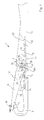
- a tongue needle 1 is illustrated in FIG. 1, one shaft 2 and one end of the shaft 2 trained hook 3.
- the hook 3 runs in one Hook tip 4 off.
- a tongue slot 5 is formed in the shaft 2, in which a Tongue 6 is pivotally mounted.
- a Tongue 6 is pivotally mounted.
- For storage e.g. an approximately cylindrical bearing pin 7, which has a pivot axis 7a defined. This is roughly correct with its central axis match.
- the tongue 6 is assigned a spiral spring 8, which in the tongue slot 5 is arranged and on the bearing journal 7 extends past. Their two ends are 11, 12 stored in corresponding seats 10, 14 in the tongue slot are trained.
- the spiral spring 8 has two Bends 15, 16, otherwise they are along their indicated in Figure 1 by a dash-dotted line L. Extends in the longitudinal direction.
- the bending points 15, 16 represent pressure areas to which the tongue 6 is connected its outside (back) 17 and its inside 18 creates when it swivels to its end positions.
- the tongue 6 further contact surfaces 23, 24 on the in the tongue slot 5 protruding end of the tongue 6 are arranged. This end has an opening 25 for receiving the journal 7 on. At the end of the tongue 6 is the opening 25 containing part of the shaft of the tongue 6 viewed.
- the contact surfaces 23, 24 are essentially two flat pressure surfaces 26, 27 assigned to the spiral spring.
- the Pressure surfaces 26, 27 are between the bending points 15, 16 arranged and, as can be seen from Figure 1, below the line L is arranged, which is the support points of the ends 11, 12 connects in the seats 10, 14.
- the Bending points 15, 16 are arranged above this line L.
- the spiral spring 8 is thus double cranked, where the crank is so flat that the through the bending points 15, 16 formed pressure surfaces with the Contact surfaces 21, 22 do not come into contact when the Printing surface 26 or 27 on the contact surface 23 or 24 is applied. This is e.g. from Figure 2 and Figure 3 can be seen.
- the lengths of the pressure surfaces 26, 27 are in the longitudinal direction of the needle preferably measured about two to three times as long as the thickness of the spiral spring 8.
- the contact surfaces 23, 24 are at the end of the Tongue shaft arranged with the swivel axis 7a define a triangle with two acute angles. This is illustrated in Figure 1 using the contact surface 24. Become the two opposite ends the contact surface 24 by connecting lines a, b with connected to the pivot axis 7a, a triangle is obtained, in which the between the connecting lines a, b and Contact surface 24 included angles W1, W2 smaller than 90 °. This measure serves the desired Rest position of the tongue 6 in both pivot directions Stabilize restoring moments.
- the pressure surfaces 26, 27 can merge or overlap each other ( Figure 4). You are through that Areas of a flat central portion 28 of the spiral spring 8 set that with appropriate swivel positions with the respective contact surface 23, 24 of the tongue 6 in contact come.
- the flat middle section 28 of the spiral spring 8 is arranged below the journal 7.
- the distance between the contact surfaces 23, 24 and the opening 25 preferably smaller than the pin diameter (diameter the tongue 25). In contrast, they are due to the bending points 15, 16 defined contact surfaces 21, 22 in one arranged greater distance from the journal 7.
- the spiral spring 8 interacts with the tongue 6 two stable rest positions R1, R2, which are shown in FIG can be seen and in which the tongue 6 the bending points 15, 16 of the spiral spring 8 is not touched.
- the tongue 6 can be swung back and forth between two end positions E1, E2, the end position E1 being determined in that the Tongue 6 rests with its spoon on the hook tip 4. This end position E1 is the closed position.
- the end position E2 is determined by the fact that the tongue 6 is transferred as far as possible to reserves and with their Outside 17 abuts the shaft 2.
- the two rest positions R1, R2 are swivel positions, which are arranged between the two end positions E1, E2.
- the rest position R1 is a tongue position in which the tongue is lifted off the hook 3 or the hook tip 4.
- the Rest position R2 is a position of the tongue 6 near the End position E2, in which the tongue 6 of the needle shaft. 2 lifted off is. The distance is so great that a thread that moved from the shaft 2 towards the hook 3 is formed in between the tongue 6 and the shaft 2 acute angle can slide.
- the latch needle 1 described so far works as follows:
- the spiral spring 8 produces in cooperation with the Tongue 6 a restoring moment M that the tongue 6 in its Rest position R1 holds.
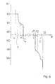
- the restoring moment M is from FIG. 6 schematically visible.
- the tongue is 6 in its rest position R1 is moment-free. Even the smallest deflections the tongue 6 out of their rest position R1 however a driving moment M1 or M2 that the deflection of the tongue 6 is directed against.
- the when driving in both directions achieved repulsive Moments M1, M2 can be different be large, e.g. depend on whether the angles W1, W2 are the same or different.
- the contact surface 22 is called the "second contact surface” and the bending area 15 is referred to as the "second pressure surface”.
- the swivel range in which the second contact surface 22 and the second pressure surface 15 are effective in Figure 6 the area B.
- the area in which the first contact surface 24 and the first printing surface 27 are effective, is in Figure 6 labeled A.
- the swivel ranges A and B can be of different sizes.
- the swivel range A in the example is larger than the swivel range B.
- the restoring torque curve is corresponding with regard the second end position E2 and the second rest position Obtain R2.
- the contact surface 23 and the pressure surface 26 form, "the third contact surface” and the "third printing surface", the one shown in Figure 6 swivel range Set C with the restoring torques M5, M6. This can be larger or smaller than the swivel range A as well as the swivel range B.
- the pressure surface and formed by the bend 16 the contact surface 21 form a "fourth printing surface” and a “fourth contact surface", which is illustrated in that in FIG Swivel range D near the end position E2 generate a restoring torque M4.
- the restoring torques M3, M4 can be independent of the restoring torques M1, M2; M5, M6 can be set and thus chosen both larger and smaller than this become.
- an intermediate area should be present by no noteworthy Return torque is present or a low one Return torque is generated.
- the thread 30 running in the direction of the arrow 31 leads the tongue 6 out of its rest position R1 and first swings it towards its reserve. As a result, the tongue 6 initially reaches the one in FIG. 3 illustrated location, i.e. in their rest position R2 acc. figure 3.
- the pressure surface 26 of the spiral spring presses in this 8 against the contact surface 23 of the tongue 6.
- Runs from the thread 30 formed stitch now further in the direction of Arrow 32 ( Figure 3) the thread 30 gradually enters the position illustrated in Figure 4. Because of the larger distance here to the pivot axis 7a, the Thread with relatively low tensions a swing moment generate that greater than the relatively low restoring torque M6, which is from the surface pairing of the contact surface 23 and the pressure surface 26 is formed.
- the latch needle 1 begins its retraction movement.
- the tongue 6 is in its rest position R2.
- exercise the thread 30 exerts a pivoting force on the tongue 6.
- This is sufficient to the small holding torque illustrated in Figure 6 M5, that of the contact surface 23 and the printing surface 26 is generated to overcome and the tongue 6 in to pivot their rest position R1 back.
- the thread slides 30 then, as illustrated in Figure 1, on the back 17 the tongue further towards the tongue spoon, the thread 30 can thanks to the tension of the stitch formed the tongue 6 out of the rest position R1 and initially the relatively low holding torque M1 and then in a second step with a time offset, the restoring torque Overcome M3.
- the stitch formed by the thread 30, is therefore without permanent expansion over the hook the tongue needle knocked off.
- the tongue reaches 6 the swivel range B and assumes a position or in this swivel range B on.
- the stitch is not permanently widened to to slide over the tongue in rest position R1, but a low thread tension is enough to the tongue to be transferred to the end position E1 or in the vicinity thereof.
- the latch needle 1 has a spring 8 on which serves to tongue 6 in one or two stable To fix rest positions R1, R2 and also to do so serves the tongue 6 out of its end positions E1, E2 to lead.
- the tongue 6 and the spring 8 are designed so that in the end positions E1, E2 and in the rest positions R1, R2 different restoring moments are applied can, the restoring moments in the end positions through other pressure surface areas 15, 16 and contact surfaces 21, 22 are generated on the tongue than in the rest positions R1, R2.
- the restoring moments M3, M4 are in the End positions E1, E2 by engaging tongue 6 with its inside 18 or its outside 17 generated on the spring 8.
- the restoring moments M1, M2, M5, M6 in the rest positions R1, R2 are created by the interaction of pressure surfaces 26, 27 the spring 8 with contact surfaces 23, 24 at the shaft end the tongue 6, which contains the bearing bore 25.
Landscapes
- Engineering & Computer Science (AREA)
- Textile Engineering (AREA)
- Knitting Machines (AREA)
Abstract
Description
Claims (10)
- Zungennadel (1), insbesondere für Strickmaschinen,wobei die Feder (8) eine erste Druckfläche (27) und die Zunge (6) eine erste Anlagefläche (24) aufweist, die der ersten Druckfläche (27) zugeordnet ist und die mit dieser in Anlage steht, wenn sich die Zunge (6) in ihrer Ruhelage (R1) befindet, undmit einem Nadelkörper (2), an dem ein Haken (3) ausgebildet ist und der einen Zungenschlitz (5) aufweist,mit einer Zunge (6), die in dem Zungenschlitz (5) zwischen zwei Endlagen (E1, E2) um eine Schwenkachse (7a) hin und her schwenkbar gelagert ist,mit einer Feder (8) zur Festlegung einer Ruhelage (R1), die einer Endlage (E1) benachbart ist,
wobei die Feder (8) eine zweite Druckfläche (15) aufweist, die von der ersten Druckfläche (27) beabstandet ist, und wobei die Zunge (6) eine zweite Anlagefläche (22) aufweist, die von der ersten Anlagefläche (24) beabstandet ist und mit der zweiten Druckfläche (15) in Anlage steht, wenn sich die Zunge (6) in ihrer der Ruhelage (R1) benachbarten Endlage (E1) befindet. - Zungennadel nach Anspruch 1, dadurch gekennzeichnet, dass die erste Druckfläche (27) und die erste Anlagefläche (24) außer Eingriff sind, wenn sich die Zunge (6) in ihrer Endlage (E1) befindet, und dass sich die zweite Druckfläche (15) und die zweite Anlagefläche (22) außer Eingriff befinden, wenn sich die Zunge (6) in ihrer Ruhelage (R1) befindet.
- Zungennadel nach Anspruch 1, dadurch gekennzeichnet, dass die erste Anlagefläche (24) in einem geringeren Abstand zu der Schwenkachse (7a) angeordnet ist als die zweite Anlagefläche (22).
- Zungennadel nach Anspruch 1, dadurch gekennzeichnet, dass die erste Anlagefläche (24) mit der Drehachse (7a) ein Dreieck festlegt dessen der Anlagefläche (24) benachbarte Innenwinkel (W1, W2) spitze Winkel sind.
- Zungennadel nach Anspruch 1, dadurch gekennzeichnet, dass die Feder (8), die Anlageflächen (24, 22) und die Druckflächen (27, 15) derart bemessen und angeordnet sind, dass in der Endlage (E1) ein Rückstellmoment (M3) erzeugt wird, dass größer ist als das Rückstellmoment (M1, M2) in der Ruhelage (R1).
- Zungennadel nach Anspruch 1, dadurch gekennzeichnet, dass die zweite Druckfläche (15) und die zweite Anlagefläche (22) miteinander erst in Berührung gelangen, wenn sich die Zunge (6) zwischen der Ruhelage (R1) und der Endlage (E1) befindet.
- Zungennadel nach Anspruch 1, dadurch gekennzeichnet, dass die erste Anlagefläche (27) eine Planfläche ist.
- Zungennadel nach Anspruch 1, dadurch gekennzeichnet, dass die Zunge (6) zur Festlegung einer weiteren stabilen Ruhelage (R2) eine dritte Anlagefläche (23) und eine von dieser beabstandete vierte Anlagefläche (21) aufweist und dass die Feder (8) eine der dritten Anlagefläche (23) zugeordnete dritte Druckfläche (26) sowie eine der vierten Anlagefläche (21) zugeordnete vierte Druckfläche (16) aufweist.
- Zungennadel nach Anspruch 1, dadurch gekennzeichnet, dass die erste und die dritte Druckfläche (27, 26) der Feder (8) einander wenigstens teilweise überdecken.
- Zungennadel nach Anspruch 1, dadurch gekennzeichnet, dass die Feder (8) eine länglich ausgebildete Biegefeder ist und dass die Druckfläche (27, 26) der Feder (8) gemessen in ihrer Längsrichtung (L) wenigstens doppelt so groß ist wie ihre Dicke.
Applications Claiming Priority (2)
| Application Number | Priority Date | Filing Date | Title |
|---|---|---|---|
| DE10051029A DE10051029C1 (de) | 2000-10-14 | 2000-10-14 | Zungennadel mit federnder Zungenunterstützung |
| DE10051029 | 2000-10-14 |
Publications (2)
| Publication Number | Publication Date |
|---|---|
| EP1197591A1 true EP1197591A1 (de) | 2002-04-17 |
| EP1197591B1 EP1197591B1 (de) | 2005-06-29 |
Family
ID=7659830
Family Applications (1)
| Application Number | Title | Priority Date | Filing Date |
|---|---|---|---|
| EP01121221A Expired - Lifetime EP1197591B1 (de) | 2000-10-14 | 2001-09-05 | Zungennadel mit federnder Zungenunterstützung |
Country Status (5)
| Country | Link |
|---|---|
| US (1) | US6439001B1 (de) |
| EP (1) | EP1197591B1 (de) |
| JP (1) | JP3857100B2 (de) |
| DE (2) | DE10051029C1 (de) |
| ES (1) | ES2244534T3 (de) |
Cited By (2)
| Publication number | Priority date | Publication date | Assignee | Title |
|---|---|---|---|---|
| EP1382729A1 (de) * | 2002-07-19 | 2004-01-21 | Groz-Beckert KG | Zungennadel |
| EP3604651A1 (de) * | 2018-08-03 | 2020-02-05 | Groz-Beckert KG | Zungennadel |
Families Citing this family (4)
| Publication number | Priority date | Publication date | Assignee | Title |
|---|---|---|---|---|
| DE10106989C2 (de) * | 2001-02-15 | 2003-04-24 | Groz Beckert Kg | Zungennadel mit fixierter Feder |
| DE102004049061B4 (de) * | 2004-10-08 | 2006-08-24 | Groz-Beckert Kg | Zungennadel |
| EP1921189B1 (de) * | 2006-11-09 | 2011-05-11 | Groz-Beckert KG | Maschinenstricknadel |
| EP2088228B1 (de) * | 2008-02-05 | 2011-10-19 | Groz-Beckert KG | Zungennadel |
Citations (4)
| Publication number | Priority date | Publication date | Assignee | Title |
|---|---|---|---|---|
| GB768051A (en) * | 1954-06-25 | 1957-02-13 | Karl Steinhof | Improvements in and relating to latch needles |
| US3050968A (en) * | 1959-06-16 | 1962-08-28 | Masujima Ryozo | Knitting needles |
| DE1410312A1 (de) * | 1958-04-19 | 1969-04-10 | Karl Steinhof App Fabrik | Zungennadel,insbesondere fuer Handstrickapparate |
| EP0866159A2 (de) * | 1997-03-22 | 1998-09-23 | Groz-Beckert Kommanditgesellschaft | Zungennadel für maschenbildende Textilmaschinen |
Family Cites Families (6)
| Publication number | Priority date | Publication date | Assignee | Title |
|---|---|---|---|---|
| DE1113537B (de) | 1954-06-25 | 1961-09-07 | Karl Steinhof App Fabrik | Handstrickapparat, Zungennadel fuer einen Handstrickapparat, und Verfahren zur Herstellung der Zungennadel |
| DE1821388U (de) * | 1960-08-08 | 1960-11-10 | Haase & Kuehn K G | Im zungenschlitz von zungennadeln, insbesondere fuer rund- und flachstrickmaschinen, eingelegte feder. |
| DE1841496U (de) * | 1961-09-18 | 1961-11-16 | Haase & Kuehn K G Nadelfabrik | Zungennadel. |
| DE3629334A1 (de) * | 1986-08-28 | 1988-03-10 | Stoll & Co H | Flachstrickmaschine |
| DE3702019C1 (de) * | 1987-01-24 | 1987-09-24 | Groz & Soehne Theodor | Zungennadel fuer maschenbildende Textilmaschinen |
| DE4142003C1 (de) * | 1991-12-19 | 1993-07-22 | Theodor Groz & Soehne & Ernst Beckert Nadelfabrik Kg, 7470 Albstadt, De |
-
2000
- 2000-10-14 DE DE10051029A patent/DE10051029C1/de not_active Expired - Lifetime
-
2001
- 2001-09-05 DE DE50106614T patent/DE50106614D1/de not_active Expired - Lifetime
- 2001-09-05 ES ES01121221T patent/ES2244534T3/es not_active Expired - Lifetime
- 2001-09-05 EP EP01121221A patent/EP1197591B1/de not_active Expired - Lifetime
- 2001-10-10 US US09/972,931 patent/US6439001B1/en not_active Expired - Lifetime
- 2001-10-11 JP JP2001313981A patent/JP3857100B2/ja not_active Expired - Lifetime
Patent Citations (4)
| Publication number | Priority date | Publication date | Assignee | Title |
|---|---|---|---|---|
| GB768051A (en) * | 1954-06-25 | 1957-02-13 | Karl Steinhof | Improvements in and relating to latch needles |
| DE1410312A1 (de) * | 1958-04-19 | 1969-04-10 | Karl Steinhof App Fabrik | Zungennadel,insbesondere fuer Handstrickapparate |
| US3050968A (en) * | 1959-06-16 | 1962-08-28 | Masujima Ryozo | Knitting needles |
| EP0866159A2 (de) * | 1997-03-22 | 1998-09-23 | Groz-Beckert Kommanditgesellschaft | Zungennadel für maschenbildende Textilmaschinen |
Cited By (5)
| Publication number | Priority date | Publication date | Assignee | Title |
|---|---|---|---|---|
| EP1382729A1 (de) * | 2002-07-19 | 2004-01-21 | Groz-Beckert KG | Zungennadel |
| US6792775B2 (en) | 2002-07-19 | 2004-09-21 | Groz-Beckert Kg | Latch needle |
| EP3604651A1 (de) * | 2018-08-03 | 2020-02-05 | Groz-Beckert KG | Zungennadel |
| WO2020025589A1 (de) | 2018-08-03 | 2020-02-06 | Groz-Beckert Kg | Zungennadel |
| US11434589B2 (en) | 2018-08-03 | 2022-09-06 | Groz-Beckert Kg | Latch needle |
Also Published As
| Publication number | Publication date |
|---|---|
| US6439001B1 (en) | 2002-08-27 |
| US20020043083A1 (en) | 2002-04-18 |
| JP2002155455A (ja) | 2002-05-31 |
| ES2244534T3 (es) | 2005-12-16 |
| EP1197591B1 (de) | 2005-06-29 |
| DE10051029C1 (de) | 2002-07-11 |
| JP3857100B2 (ja) | 2006-12-13 |
| DE50106614D1 (de) | 2005-08-04 |
Similar Documents
| Publication | Publication Date | Title |
|---|---|---|
| EP3201050B1 (de) | Schlosszunge mit einem torsionsstab | |
| DE19833508B4 (de) | Nadelwählvorrichtung, insbesondere zur Auswahl der Rippnadeln in Rundstrickmaschinen, Rundwirkmaschinen oder Strumpfwirkmaschinen zur Herstellung von Strick- und Strumpfwaren | |
| EP0278053B1 (de) | Zungennadel für maschenbildende Textilmaschinen | |
| DE3039946C2 (de) | Vorrichtung zum Verhindern einer Drehbewegung von mindestens zwei, an einer Nockenwelle einer Brennkraftmaschine angreifenden Rollenstößeln | |
| DE3421509A1 (de) | Schliessvorrichtung fuer eine tuer | |
| DE68903777T2 (de) | Schreibgeraet und zusammenbauverfahren. | |
| EP1028185B1 (de) | Umhängenadel zur Maschenübertragung | |
| EP1197591B1 (de) | Zungennadel mit federnder Zungenunterstützung | |
| WO2018236324A2 (de) | Haltevorrichtung für eine frontblende einer schublade | |
| DE102008043811A1 (de) | Haushaltsgerät mit Lagerzapfen mit Verdrehsicherung für Lagerbuchse | |
| EP0207059B1 (de) | Verschlussmechanik für Ordner | |
| DE19712124C2 (de) | Zungennadel für maschenbildende Textilmaschinen | |
| EP2088228A1 (de) | Zungennadel | |
| DE2632859C2 (de) | Nadelauswahleinrichtung für eine Strickmaschine | |
| DE102018101342A1 (de) | Ausziehführung für einen Schubkasten und Verfahren zum Ausrichten eines Schubkastens an einer Ausziehführung | |
| EP1619282B1 (de) | Nadel für ein maschenbildendes System | |
| DE2935436C2 (de) | ||
| DE102006005384B4 (de) | Abzugskamm für Strick- oder Wirkmaschine | |
| DE102010055235A1 (de) | Konstruktion eines senkrechten Vollumlaufgreifers für eine Nähmaschine | |
| EP1741502B1 (de) | Verfahren zum Herstellen von Nadeln für Textilmaschinen | |
| DE69710129T2 (de) | Haken für Einzylinder-Rundstrickmaschine oder Strumpfstrickmaschine mit Zylinder und kreisförmigem oder halbkreisförmigem Nadelteller | |
| EP1887117B1 (de) | Zungennadel für maschenbildende Textilmaschine | |
| DE20122827U1 (de) | Möbelscharnier mit Öffnungsmechanik, insbesondere für Möbeltüren | |
| EP3012363B1 (de) | Maschinenstricknadel, anordnung zur maschenbildung sowie verwendung dieser anordnung in einem verfahren auf einer strickmaschine | |
| WO2022248143A1 (de) | Platine, strickvorrichtung und strickverfahren zum erzeugen von maschenwaren |
Legal Events
| Date | Code | Title | Description |
|---|---|---|---|
| PUAI | Public reference made under article 153(3) epc to a published international application that has entered the european phase |
Free format text: ORIGINAL CODE: 0009012 |
|
| AK | Designated contracting states |
Kind code of ref document: A1 Designated state(s): AT BE CH CY DE DK ES FI FR GB GR IE IT LI LU MC NL PT SE TR Kind code of ref document: A1 Designated state(s): DE ES FR GB IT |
|
| AX | Request for extension of the european patent |
Free format text: AL;LT;LV;MK;RO;SI |
|
| 17P | Request for examination filed |
Effective date: 20020511 |
|
| AKX | Designation fees paid |
Free format text: AT BE CH CY DE LI |
|
| RBV | Designated contracting states (corrected) |
Designated state(s): DE ES FR GB IT |
|
| GRAP | Despatch of communication of intention to grant a patent |
Free format text: ORIGINAL CODE: EPIDOSNIGR1 |
|
| GRAS | Grant fee paid |
Free format text: ORIGINAL CODE: EPIDOSNIGR3 |
|
| 17Q | First examination report despatched |
Effective date: 20040917 |
|
| GRAJ | Information related to disapproval of communication of intention to grant by the applicant or resumption of examination proceedings by the epo deleted |
Free format text: ORIGINAL CODE: EPIDOSDIGR1 |
|
| GRAP | Despatch of communication of intention to grant a patent |
Free format text: ORIGINAL CODE: EPIDOSNIGR1 |
|
| GRAA | (expected) grant |
Free format text: ORIGINAL CODE: 0009210 |
|
| AK | Designated contracting states |
Kind code of ref document: B1 Designated state(s): DE ES FR GB IT |
|
| REG | Reference to a national code |
Ref country code: GB Ref legal event code: FG4D Free format text: NOT ENGLISH |
|
| GBT | Gb: translation of ep patent filed (gb section 77(6)(a)/1977) |
Effective date: 20050629 |
|
| REF | Corresponds to: |
Ref document number: 50106614 Country of ref document: DE Date of ref document: 20050804 Kind code of ref document: P |
|
| REG | Reference to a national code |
Ref country code: ES Ref legal event code: FG2A Ref document number: 2244534 Country of ref document: ES Kind code of ref document: T3 |
|
| ET | Fr: translation filed | ||
| PLBE | No opposition filed within time limit |
Free format text: ORIGINAL CODE: 0009261 |
|
| STAA | Information on the status of an ep patent application or granted ep patent |
Free format text: STATUS: NO OPPOSITION FILED WITHIN TIME LIMIT |
|
| 26N | No opposition filed |
Effective date: 20060330 |
|
| REG | Reference to a national code |
Ref country code: FR Ref legal event code: PLFP Year of fee payment: 16 |
|
| REG | Reference to a national code |
Ref country code: FR Ref legal event code: PLFP Year of fee payment: 17 |
|
| REG | Reference to a national code |
Ref country code: FR Ref legal event code: PLFP Year of fee payment: 18 |
|
| PGFP | Annual fee paid to national office [announced via postgrant information from national office to epo] |
Ref country code: GB Payment date: 20200826 Year of fee payment: 20 Ref country code: FR Payment date: 20200812 Year of fee payment: 20 |
|
| PGFP | Annual fee paid to national office [announced via postgrant information from national office to epo] |
Ref country code: IT Payment date: 20200812 Year of fee payment: 20 |
|
| PGFP | Annual fee paid to national office [announced via postgrant information from national office to epo] |
Ref country code: DE Payment date: 20200930 Year of fee payment: 20 Ref country code: ES Payment date: 20201005 Year of fee payment: 20 |
|
| REG | Reference to a national code |
Ref country code: DE Ref legal event code: R071 Ref document number: 50106614 Country of ref document: DE |
|
| REG | Reference to a national code |
Ref country code: GB Ref legal event code: PE20 Expiry date: 20210904 |
|
| PG25 | Lapsed in a contracting state [announced via postgrant information from national office to epo] |
Ref country code: GB Free format text: LAPSE BECAUSE OF EXPIRATION OF PROTECTION Effective date: 20210904 |
|
| REG | Reference to a national code |
Ref country code: ES Ref legal event code: FD2A Effective date: 20211227 |
|
| PG25 | Lapsed in a contracting state [announced via postgrant information from national office to epo] |
Ref country code: ES Free format text: LAPSE BECAUSE OF EXPIRATION OF PROTECTION Effective date: 20210906 |