EP1194701B1 - Nadellager und pumpeneinheit mit einem nadellager - Google Patents
Nadellager und pumpeneinheit mit einem nadellager Download PDFInfo
- Publication number
- EP1194701B1 EP1194701B1 EP00947774A EP00947774A EP1194701B1 EP 1194701 B1 EP1194701 B1 EP 1194701B1 EP 00947774 A EP00947774 A EP 00947774A EP 00947774 A EP00947774 A EP 00947774A EP 1194701 B1 EP1194701 B1 EP 1194701B1
- Authority
- EP
- European Patent Office
- Prior art keywords
- bearing
- inner race
- pump
- needle bearing
- rolling
- Prior art date
- Legal status (The legal status is an assumption and is not a legal conclusion. Google has not performed a legal analysis and makes no representation as to the accuracy of the status listed.)
- Expired - Lifetime
Links
Images
Classifications
-
- F—MECHANICAL ENGINEERING; LIGHTING; HEATING; WEAPONS; BLASTING
- F16—ENGINEERING ELEMENTS AND UNITS; GENERAL MEASURES FOR PRODUCING AND MAINTAINING EFFECTIVE FUNCTIONING OF MACHINES OR INSTALLATIONS; THERMAL INSULATION IN GENERAL
- F16C—SHAFTS; FLEXIBLE SHAFTS; ELEMENTS OR CRANKSHAFT MECHANISMS; ROTARY BODIES OTHER THAN GEARING ELEMENTS; BEARINGS
- F16C35/00—Rigid support of bearing units; Housings, e.g. caps, covers
- F16C35/04—Rigid support of bearing units; Housings, e.g. caps, covers in the case of ball or roller bearings
- F16C35/06—Mounting or dismounting of ball or roller bearings; Fixing them onto shaft or in housing
- F16C35/067—Fixing them in a housing
-
- B—PERFORMING OPERATIONS; TRANSPORTING
- B60—VEHICLES IN GENERAL
- B60T—VEHICLE BRAKE CONTROL SYSTEMS OR PARTS THEREOF; BRAKE CONTROL SYSTEMS OR PARTS THEREOF, IN GENERAL; ARRANGEMENT OF BRAKING ELEMENTS ON VEHICLES IN GENERAL; PORTABLE DEVICES FOR PREVENTING UNWANTED MOVEMENT OF VEHICLES; VEHICLE MODIFICATIONS TO FACILITATE COOLING OF BRAKES
- B60T17/00—Component parts, details, or accessories of power brake systems not covered by groups B60T8/00, B60T13/00 or B60T15/00, or presenting other characteristic features
- B60T17/02—Arrangements of pumps or compressors, or control devices therefor
-
- B—PERFORMING OPERATIONS; TRANSPORTING
- B60—VEHICLES IN GENERAL
- B60T—VEHICLE BRAKE CONTROL SYSTEMS OR PARTS THEREOF; BRAKE CONTROL SYSTEMS OR PARTS THEREOF, IN GENERAL; ARRANGEMENT OF BRAKING ELEMENTS ON VEHICLES IN GENERAL; PORTABLE DEVICES FOR PREVENTING UNWANTED MOVEMENT OF VEHICLES; VEHICLE MODIFICATIONS TO FACILITATE COOLING OF BRAKES
- B60T8/00—Arrangements for adjusting wheel-braking force to meet varying vehicular or ground-surface conditions, e.g. limiting or varying distribution of braking force
- B60T8/32—Arrangements for adjusting wheel-braking force to meet varying vehicular or ground-surface conditions, e.g. limiting or varying distribution of braking force responsive to a speed condition, e.g. acceleration or deceleration
- B60T8/34—Arrangements for adjusting wheel-braking force to meet varying vehicular or ground-surface conditions, e.g. limiting or varying distribution of braking force responsive to a speed condition, e.g. acceleration or deceleration having a fluid pressure regulator responsive to a speed condition
- B60T8/36—Arrangements for adjusting wheel-braking force to meet varying vehicular or ground-surface conditions, e.g. limiting or varying distribution of braking force responsive to a speed condition, e.g. acceleration or deceleration having a fluid pressure regulator responsive to a speed condition including a pilot valve responding to an electromagnetic force
- B60T8/3615—Electromagnetic valves specially adapted for anti-lock brake and traction control systems
- B60T8/3675—Electromagnetic valves specially adapted for anti-lock brake and traction control systems integrated in modulator units
- B60T8/368—Electromagnetic valves specially adapted for anti-lock brake and traction control systems integrated in modulator units combined with other mechanical components, e.g. pump units, master cylinders
-
- B—PERFORMING OPERATIONS; TRANSPORTING
- B60—VEHICLES IN GENERAL
- B60T—VEHICLE BRAKE CONTROL SYSTEMS OR PARTS THEREOF; BRAKE CONTROL SYSTEMS OR PARTS THEREOF, IN GENERAL; ARRANGEMENT OF BRAKING ELEMENTS ON VEHICLES IN GENERAL; PORTABLE DEVICES FOR PREVENTING UNWANTED MOVEMENT OF VEHICLES; VEHICLE MODIFICATIONS TO FACILITATE COOLING OF BRAKES
- B60T8/00—Arrangements for adjusting wheel-braking force to meet varying vehicular or ground-surface conditions, e.g. limiting or varying distribution of braking force
- B60T8/32—Arrangements for adjusting wheel-braking force to meet varying vehicular or ground-surface conditions, e.g. limiting or varying distribution of braking force responsive to a speed condition, e.g. acceleration or deceleration
- B60T8/34—Arrangements for adjusting wheel-braking force to meet varying vehicular or ground-surface conditions, e.g. limiting or varying distribution of braking force responsive to a speed condition, e.g. acceleration or deceleration having a fluid pressure regulator responsive to a speed condition
- B60T8/40—Arrangements for adjusting wheel-braking force to meet varying vehicular or ground-surface conditions, e.g. limiting or varying distribution of braking force responsive to a speed condition, e.g. acceleration or deceleration having a fluid pressure regulator responsive to a speed condition comprising an additional fluid circuit including fluid pressurising means for modifying the pressure of the braking fluid, e.g. including wheel driven pumps for detecting a speed condition, or pumps which are controlled by means independent of the braking system
- B60T8/4018—Pump units characterised by their drive mechanisms
- B60T8/4022—Pump units driven by an individual electric motor
-
- B—PERFORMING OPERATIONS; TRANSPORTING
- B60—VEHICLES IN GENERAL
- B60T—VEHICLE BRAKE CONTROL SYSTEMS OR PARTS THEREOF; BRAKE CONTROL SYSTEMS OR PARTS THEREOF, IN GENERAL; ARRANGEMENT OF BRAKING ELEMENTS ON VEHICLES IN GENERAL; PORTABLE DEVICES FOR PREVENTING UNWANTED MOVEMENT OF VEHICLES; VEHICLE MODIFICATIONS TO FACILITATE COOLING OF BRAKES
- B60T8/00—Arrangements for adjusting wheel-braking force to meet varying vehicular or ground-surface conditions, e.g. limiting or varying distribution of braking force
- B60T8/32—Arrangements for adjusting wheel-braking force to meet varying vehicular or ground-surface conditions, e.g. limiting or varying distribution of braking force responsive to a speed condition, e.g. acceleration or deceleration
- B60T8/34—Arrangements for adjusting wheel-braking force to meet varying vehicular or ground-surface conditions, e.g. limiting or varying distribution of braking force responsive to a speed condition, e.g. acceleration or deceleration having a fluid pressure regulator responsive to a speed condition
- B60T8/40—Arrangements for adjusting wheel-braking force to meet varying vehicular or ground-surface conditions, e.g. limiting or varying distribution of braking force responsive to a speed condition, e.g. acceleration or deceleration having a fluid pressure regulator responsive to a speed condition comprising an additional fluid circuit including fluid pressurising means for modifying the pressure of the braking fluid, e.g. including wheel driven pumps for detecting a speed condition, or pumps which are controlled by means independent of the braking system
- B60T8/4031—Pump units characterised by their construction or mounting
-
- F—MECHANICAL ENGINEERING; LIGHTING; HEATING; WEAPONS; BLASTING
- F04—POSITIVE - DISPLACEMENT MACHINES FOR LIQUIDS; PUMPS FOR LIQUIDS OR ELASTIC FLUIDS
- F04B—POSITIVE-DISPLACEMENT MACHINES FOR LIQUIDS; PUMPS
- F04B1/00—Multi-cylinder machines or pumps characterised by number or arrangement of cylinders
- F04B1/04—Multi-cylinder machines or pumps characterised by number or arrangement of cylinders having cylinders in star- or fan-arrangement
- F04B1/0404—Details or component parts
- F04B1/0413—Cams
-
- F—MECHANICAL ENGINEERING; LIGHTING; HEATING; WEAPONS; BLASTING
- F04—POSITIVE - DISPLACEMENT MACHINES FOR LIQUIDS; PUMPS FOR LIQUIDS OR ELASTIC FLUIDS
- F04B—POSITIVE-DISPLACEMENT MACHINES FOR LIQUIDS; PUMPS
- F04B1/00—Multi-cylinder machines or pumps characterised by number or arrangement of cylinders
- F04B1/04—Multi-cylinder machines or pumps characterised by number or arrangement of cylinders having cylinders in star- or fan-arrangement
- F04B1/0404—Details or component parts
- F04B1/0413—Cams
- F04B1/0417—Cams consisting of two or more cylindrical elements, e.g. rollers
-
- F—MECHANICAL ENGINEERING; LIGHTING; HEATING; WEAPONS; BLASTING
- F04—POSITIVE - DISPLACEMENT MACHINES FOR LIQUIDS; PUMPS FOR LIQUIDS OR ELASTIC FLUIDS
- F04B—POSITIVE-DISPLACEMENT MACHINES FOR LIQUIDS; PUMPS
- F04B17/00—Pumps characterised by combination with, or adaptation to, specific driving engines or motors
- F04B17/03—Pumps characterised by combination with, or adaptation to, specific driving engines or motors driven by electric motors
-
- F—MECHANICAL ENGINEERING; LIGHTING; HEATING; WEAPONS; BLASTING
- F16—ENGINEERING ELEMENTS AND UNITS; GENERAL MEASURES FOR PRODUCING AND MAINTAINING EFFECTIVE FUNCTIONING OF MACHINES OR INSTALLATIONS; THERMAL INSULATION IN GENERAL
- F16C—SHAFTS; FLEXIBLE SHAFTS; ELEMENTS OR CRANKSHAFT MECHANISMS; ROTARY BODIES OTHER THAN GEARING ELEMENTS; BEARINGS
- F16C19/00—Bearings with rolling contact, for exclusively rotary movement
- F16C19/22—Bearings with rolling contact, for exclusively rotary movement with bearing rollers essentially of the same size in one or more circular rows, e.g. needle bearings
- F16C19/44—Needle bearings
- F16C19/46—Needle bearings with one row or needles
-
- F—MECHANICAL ENGINEERING; LIGHTING; HEATING; WEAPONS; BLASTING
- F16—ENGINEERING ELEMENTS AND UNITS; GENERAL MEASURES FOR PRODUCING AND MAINTAINING EFFECTIVE FUNCTIONING OF MACHINES OR INSTALLATIONS; THERMAL INSULATION IN GENERAL
- F16C—SHAFTS; FLEXIBLE SHAFTS; ELEMENTS OR CRANKSHAFT MECHANISMS; ROTARY BODIES OTHER THAN GEARING ELEMENTS; BEARINGS
- F16C21/00—Combinations of sliding-contact bearings with ball or roller bearings, for exclusively rotary movement
- F16C21/005—Combinations of sliding-contact bearings with ball or roller bearings, for exclusively rotary movement the external zone of a bearing with rolling members, e.g. needles, being cup-shaped, with or without a separate thrust-bearing disc or ring, e.g. for universal joints
-
- F—MECHANICAL ENGINEERING; LIGHTING; HEATING; WEAPONS; BLASTING
- F16—ENGINEERING ELEMENTS AND UNITS; GENERAL MEASURES FOR PRODUCING AND MAINTAINING EFFECTIVE FUNCTIONING OF MACHINES OR INSTALLATIONS; THERMAL INSULATION IN GENERAL
- F16C—SHAFTS; FLEXIBLE SHAFTS; ELEMENTS OR CRANKSHAFT MECHANISMS; ROTARY BODIES OTHER THAN GEARING ELEMENTS; BEARINGS
- F16C33/00—Parts of bearings; Special methods for making bearings or parts thereof
- F16C33/30—Parts of ball or roller bearings
- F16C33/58—Raceways; Race rings
-
- F—MECHANICAL ENGINEERING; LIGHTING; HEATING; WEAPONS; BLASTING
- F16—ENGINEERING ELEMENTS AND UNITS; GENERAL MEASURES FOR PRODUCING AND MAINTAINING EFFECTIVE FUNCTIONING OF MACHINES OR INSTALLATIONS; THERMAL INSULATION IN GENERAL
- F16C—SHAFTS; FLEXIBLE SHAFTS; ELEMENTS OR CRANKSHAFT MECHANISMS; ROTARY BODIES OTHER THAN GEARING ELEMENTS; BEARINGS
- F16C35/00—Rigid support of bearing units; Housings, e.g. caps, covers
- F16C35/04—Rigid support of bearing units; Housings, e.g. caps, covers in the case of ball or roller bearings
- F16C35/06—Mounting or dismounting of ball or roller bearings; Fixing them onto shaft or in housing
-
- H—ELECTRICITY
- H02—GENERATION; CONVERSION OR DISTRIBUTION OF ELECTRIC POWER
- H02K—DYNAMO-ELECTRIC MACHINES
- H02K7/00—Arrangements for handling mechanical energy structurally associated with dynamo-electric machines, e.g. structural association with mechanical driving motors or auxiliary dynamo-electric machines
- H02K7/06—Means for converting reciprocating motion into rotary motion or vice versa
- H02K7/075—Means for converting reciprocating motion into rotary motion or vice versa using crankshafts or eccentrics
-
- F—MECHANICAL ENGINEERING; LIGHTING; HEATING; WEAPONS; BLASTING
- F16—ENGINEERING ELEMENTS AND UNITS; GENERAL MEASURES FOR PRODUCING AND MAINTAINING EFFECTIVE FUNCTIONING OF MACHINES OR INSTALLATIONS; THERMAL INSULATION IN GENERAL
- F16C—SHAFTS; FLEXIBLE SHAFTS; ELEMENTS OR CRANKSHAFT MECHANISMS; ROTARY BODIES OTHER THAN GEARING ELEMENTS; BEARINGS
- F16C2360/00—Engines or pumps
- F16C2360/42—Pumps with cylinders or pistons
Definitions
- the invention is based on a pump unit with a needle bearing according to the preamble of claim 1.
- the pump unit has an electric drive motor, the shaft in an eccentrically shaped sleeve of a component engages torque transmitting.
- the sleeve is motor side and engine facing away, each with a rolling bearing in a pump block stored, to which the engine is also attached.
- the sleeve carries immediately adjacent to the engine-side bearings a needle roller bearing.
- the sleeve serves as an inner ring of the needle bearing, whose in one Caged needles carry a needle bush as an outer ring.
- At the outer ring pump piston, which radial to the axis of Motor shaft are received in the pump block.
- the outer ring of the Needle bearing is at its two end faces with a radially to directed inside Board provided, which overlap the needles frontally.
- Around the axial position of needles and outer ring on the inner ring ensure is a board of the outer ring to the playful attack on the end face of the inner ring provided the engine-side bearing.
- On the side of the engine-facing bearing is in contrast to the formed eccentric sleeve molded collar, to the other board on the outer ring can start.
- disadvantages because of the federal have the two bearings a relatively large distance on, and the federal government requires a costly cutting or deformation of the sleeve having the component. Since the motor-side board of the needle bushing frontally completely flat is formed, there is also the risk that he is in the Wear - related contact with a bearing cover disc of the engine-side bearing causes damage.
- the pump unit according to the invention with the features of Claim 1 is advantageous insofar as with little effort a latching of the needle bearing on the shaft of the drive motor is achieved in that the outer ring due to positive engagement his board between the two with adhesion on the shaft fixed inner rings of needle roller bearings and bearings is performed. Another guide element or a contact surface for the Outer ring is not required, which in addition to cost advantages to one axial shortening of the overall arrangement leads, which in turn one compact and inexpensive design of the pump block allows.
- the design of the inner ring of the Needle bearing as an eccentric the manufacture of the motor shaft cheaper and cheaper obtained a high bending stiffness of the shaft.
- the measure listed in claim 2 is a surface area defined contact between the board of the outer ring of the Needle bearing and the inner ring of the bearing specified.
- the Camber or protuberance prevents tarnishing of the board against a bearing cover disc of the rolling bearing and its wear.
- Crook or Protrusion is a material volume available placed during the life of the Can reduce pump unit due to wear. Damage to the Needle bearings or roller bearings are avoided.
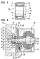
- FIG. 1 shows a Needle bearing in section
- Figure 2 is a longitudinal section of a Pump unit with a needle bearing according to FIG. 1.
- Needle bearing 10 has an inner ring 11, an outer ring 12th and received between the inner ring and the outer ring, in a cage 13 guided needles 14.
- the inner ring 11 is formed as an eccentric sleeve with an axis 15.
- the outer ring 12 has an axis 16 and is in the form of a Needle box designed.
- the outer ring 12 is at its two End faces with a radially inboard board 17th and 18 provided.
- the board 17 has a small radial Width on and only overlaps the needles 14.
- the board 18, however, has a larger radial width and engages over an end face 19 of the inner ring 11.
- the board 18 reaches almost the inner diameter of the inner ring 11 where this has its smallest wall thickness.
- the board 18 At his Inner edge of the board 18 has an axial, from the end face 19 of the inner ring 11 directed away bend or protuberance 20.
- the bend or protuberance 20 forms a concentric with the axis 16 of the outer ring extending Material bead, which faces away from the inner ring 11 Face 22 of the board 18 surmounted and in a End face 21 terminates, which is parallel to the end face 22nd runs.
- Pump unit 25 is for use in slip-controlled hydraulic vehicle brake systems determined.
- the Pump unit 25 has a radial piston pump 26 with two in a pump block 27 arranged pump elements 28.
- At the pump block 27 is an electric drive motor 29 of the Radial piston pump 26 attached.
- the drive motor 29 has a Shaft 30, which with its pump block facing away in a plain bearing 31 is mounted.
- the in a housing 32nd the plain bearing of the drive motor 29 forms a Floating bearing for the shaft 30.
- Pump block side is the shaft 30 in a rolling bearing 33 in the form of a radial deep groove ball bearing stored.
- An outer ring 34 of the rolling bearing 33 sits with a press fit in a housing cover or flange 35th of the housing 32.
- An inner ring 38 of the rolling bearing 33 is press-fitted the shaft 30 of the drive motor 29 is held.
- the balls 39 are at both ends of the rolling bearing 33 through Bearing covers 40 covered.
- the rolling bearing 33 is a Fixed bearing of the shaft 30.
- Needle bearing 10 is arranged.
- the inner ring 11 of the needle bearing 10 is leaving a gap to the inner ring 38 of Rolling bearing 33 on the shaft 30 of the drive motor 29th pressed.
- the axis 15 of the needle bearing 10 coincides the axis 44 of the shaft 30 together.
- the diameter of the Needle bearing 10 receiving shaft portion 45 is only slightly opposite to the rolling bearing 33 to Slide bearing 31 extending portion 46 of the shaft 30th reduced. This therefore has a high bending stiffness on.
- the Needle bearing 10 On the outer ring 12 of the needle bearing 10 engage shell side in a direction perpendicular to the shaft axis 44th extending plane oscillating movable pump piston 47th the pump elements 28 of the radial piston pump 26 at.
- the Needle bearing 10 is in a manner on the shaft 30th arranged that the radially wider board 18 in the gap 43rd between the inner ring 11 of the needle bearing 10 and the Inner ring 38 of the rolling bearing 33 with little axial play intervenes. This is a hold of the outer ring 12 of the Needle bearing 10 achieved in both axial directions.
- the from the Game of the board 18 minor allowed in the slot 43 axial migration of the outer ring 12 is on one side from the inner ring 11 of the needle bearing 10 and on the other Side bounded by the inner ring 38 of the rolling bearing 33. there only reaches the end face 21 of the crank or Protrusion 20 on board 18 in contact with the inner ring 38th of the rolling bearing 33.
- the needle bearing side bearing cover disc 40th the rolling bearing 33 is not touched by the board 18. While the life of the pump unit 25 represents the cranking or protuberance 20 exposed to wear Material volume available. The thus obtained stop the outer ring 12 makes a pump block side Contact surface superfluous.
- the shaft 30 of the drive motor 29 is at its Pump block-side end portion 49 with another Needle bearing 50 in the bore 37 of the pump block 27th stored. As a result, the deflection of the shaft 30th additionally reduced.
- the needle bearing 50 forms a second Floating bearing of the shaft 30.
Landscapes
- Engineering & Computer Science (AREA)
- General Engineering & Computer Science (AREA)
- Mechanical Engineering (AREA)
- Physics & Mathematics (AREA)
- Fluid Mechanics (AREA)
- Transportation (AREA)
- Electromagnetism (AREA)
- Power Engineering (AREA)
- Rolling Contact Bearings (AREA)
- Details Of Reciprocating Pumps (AREA)
- Motor Or Generator Frames (AREA)
- Connection Of Motors, Electrical Generators, Mechanical Devices, And The Like (AREA)
- Shafts, Cranks, Connecting Bars, And Related Bearings (AREA)
- Reciprocating Pumps (AREA)
- Valves And Accessory Devices For Braking Systems (AREA)
Description
Claims (2)
- Pumpeneinheit (25), insbesondere für schlupfgeregelte hydraulische Fahrzeug-Bremsanlagen, mit einer Radialkolbenpumpe (26) mit mindestens einem Pumpenkolben (47) in einem Pumpenblock (27), mit einem an den Pumpenblock (27) angebauten Antriebsmotor (29), mit einer vom Antriebsmotor (29) antreibbaren Welle (30), welche wenigstens mittelbar einen Innenring (38) eines Wälzlagers (33) durchgreift und unmittelbar benachbart zu diesem ein Nadellager (10) trägt, das einen als exzentrische Hülse ausgebildeten Innenring (11) und einen Außenring (12) in Form einer Nadelbüchse sowie Nadeln (14) zwischen Innenring (11) und Außenring (12) aufweist,wobei der Außenring (12) an seinen beiden Stirnseiten jeweils mit einem radial nach innen gerichteten Bord (17, 18) versehen ist, von denen einer zum Angriff am Innenring (38) des Wälzlagers (33) vorgesehen ist, während der Pumpenkolben (47) der Radialkolbenpumpe (26) am Mantel des Außenrings (12) des Nadellagers (10) angreift, dadurch gekennzeichnet, daß der Innenring (11) des Nadellagers (10) ebenso wie der Innenring (38) des Wälzlagers (33) auf die Welle (30) aufgepreßt sind und daß lediglich der zum Angriff am Innenring (38) des Wälzlagers (33) vorgesehene Bord (18) des Außenrings (12) des Nadellagers (10) zur Sicherung der axialen Lage von Nadeln (14) und Außenring (12) über eine Stirnfläche (19) des Innenringes (11) greift, wobei dieser Bord (18) in einen Spalt zwischen den Innenringen (11, 38) von Nadellager (10) und Wälzlager (33) greift.
- Pumpeneinheit nach Anspruch 1, dadurch gekennzeichnet, daß der die Stirnfläche des Innenrings übergreifende Bord (18) des Außenrings (12) des Nadellagers (10) an seinem Innenrand eine axiale, gegen den Innenring (38) des Wälzlagers (33) gerichtete Kröpfung oder Ausstülpung (20) hat, deren radial verlaufende ebene Stirnfläche (21) zum Anlauf gegen den Innenring (38) des Wälzlagers (33) vorgesehen ist.
Applications Claiming Priority (3)
| Application Number | Priority Date | Filing Date | Title |
|---|---|---|---|
| DE19928480 | 1999-06-22 | ||
| DE19928480A DE19928480A1 (de) | 1999-06-22 | 1999-06-22 | Nadellager und Pumpeneinheit mit einem Nadellager |
| PCT/DE2000/001815 WO2000079144A1 (de) | 1999-06-22 | 2000-06-03 | Nadellager und pumpeneinheit mit einem nadellager |
Publications (2)
| Publication Number | Publication Date |
|---|---|
| EP1194701A1 EP1194701A1 (de) | 2002-04-10 |
| EP1194701B1 true EP1194701B1 (de) | 2004-02-11 |
Family
ID=7912089
Family Applications (1)
| Application Number | Title | Priority Date | Filing Date |
|---|---|---|---|
| EP00947774A Expired - Lifetime EP1194701B1 (de) | 1999-06-22 | 2000-06-03 | Nadellager und pumpeneinheit mit einem nadellager |
Country Status (5)
| Country | Link |
|---|---|
| US (1) | US6732631B1 (de) |
| EP (1) | EP1194701B1 (de) |
| JP (1) | JP4713797B2 (de) |
| DE (2) | DE19928480A1 (de) |
| WO (1) | WO2000079144A1 (de) |
Families Citing this family (23)
| Publication number | Priority date | Publication date | Assignee | Title |
|---|---|---|---|---|
| DE10131804A1 (de) | 2000-07-29 | 2002-02-07 | Bosch Gmbh Robert | Pumpenaggregat für eine hydraulische Fahrzeugbremsanlage |
| EP1307370B1 (de) * | 2000-07-29 | 2004-06-16 | Robert Bosch Gmbh | Pumpenaggregat für eine hydraulische fahrzeugbremsanlage |
| DE10063757B4 (de) * | 2000-12-21 | 2010-04-01 | Robert Bosch Gmbh | Pumpenaggregat für eine hydraulische Fahrzeugbremsanlage |
| DE10111574B4 (de) * | 2001-03-10 | 2010-08-19 | Schaeffler Technologies Gmbh & Co. Kg | Lageranordnung für eine Radialkolbenpumpe |
| JP4050484B2 (ja) * | 2001-04-30 | 2008-02-20 | 本田技研工業株式会社 | エンジンのクランクシャフト支持構造 |
| CN1846340A (zh) * | 2003-09-02 | 2006-10-11 | 博世株式会社 | 具有偏心部的马达以及使用该马达的泵装置 |
| DE102004045438B3 (de) * | 2004-09-18 | 2006-06-01 | Ab Skf | Verfahren zur Herstellung eines Lagerrings |
| DE102005013059A1 (de) * | 2004-10-23 | 2006-05-11 | Continental Teves Ag & Co. Ohg | Fahrzeughydraulikaggregat insbesondere für Bremsanlagen |
| CN101278122B (zh) * | 2005-09-27 | 2013-08-21 | 史密特传动责任有限公司 | 带有具有改进曲柄轴承的星形液压缸的液压机 |
| US8104779B2 (en) * | 2006-12-21 | 2012-01-31 | Roller Bearing Company Of America, Inc. | Bearing for follower or cam |
| CN101877510B (zh) * | 2009-04-29 | 2014-09-03 | 德昌电机(深圳)有限公司 | 用于防抱死制动系统的电机组件 |
| KR101070423B1 (ko) | 2009-08-11 | 2011-10-06 | 엘지이노텍 주식회사 | 차량용 에이비에스 모터 |
| DE102010001792B4 (de) | 2010-02-11 | 2022-12-01 | Robert Bosch Gmbh | Antriebseinrichtung, insbesondere Elektromotor, zum Antrieb eines Aggregates |
| DE102010024280B4 (de) * | 2010-06-18 | 2012-11-22 | Diehl Ako Stiftung & Co. Kg | Stellvorrichtung, insbesondere für ein Heizkörperventil |
| US8333572B2 (en) * | 2010-07-06 | 2012-12-18 | Jongherya Co., Ltd. | Pump |
| DE102011080036A1 (de) * | 2011-07-28 | 2013-01-31 | Zf Friedrichshafen Ag | Radnahe Antriebseinheit für ein Kraftfahrzeug |
| CN103541992B (zh) * | 2013-10-08 | 2016-03-16 | 上海斐赛轴承科技有限公司 | 带凸出量的深沟球轴承、带间隙的轴承对及低温升振动棒 |
| DE102015213022A1 (de) * | 2015-07-13 | 2017-01-19 | Bühler Motor GmbH | Elektromotor |
| DE102016204302B4 (de) * | 2016-03-16 | 2020-02-13 | Schaeffler Technologies AG & Co. KG | Wälzlager für eine Radialkolbenpumpe sowie Radialkolbenpumpe mit dem Wälzlager |
| DE102018216558A1 (de) * | 2018-09-27 | 2020-04-02 | Robert Bosch Gmbh | Antriebseinrichtung, Hydraulikpumpe, Kraftfahrzeug |
| CN112013050B (zh) * | 2020-09-14 | 2024-08-23 | 宁波市镇海甬欣机电科技有限公司 | 一种刹车装置及应用有该刹车装置的管状电机 |
| WO2022122087A1 (de) | 2020-12-09 | 2022-06-16 | Brose Fahrzeugteile SE & Co. Kommanditgesellschaft, Würzburg | Elektromotor |
| DE102021116460B4 (de) * | 2021-06-25 | 2025-10-02 | Bühler Motor GmbH | Lageranordnung für einen Pumpenmotor |
Citations (4)
| Publication number | Priority date | Publication date | Assignee | Title |
|---|---|---|---|---|
| EP0637690A1 (de) * | 1993-05-14 | 1995-02-08 | Sumitomo Electric Industries, Limited | Kolbenpumpe |
| DE4433972A1 (de) * | 1994-09-23 | 1996-03-28 | Teves Gmbh Alfred | Elektromotor, Pumpe sowie ein Elektromotor/Pumpenaggregat |
| DE19720615C1 (de) * | 1997-05-16 | 1998-06-04 | Bosch Gmbh Robert | Pumpenaggregat, insbesondere für schlupfgeregelte Bremsanlagen von Fahrzeugen |
| DE19706124A1 (de) * | 1997-02-17 | 1998-08-20 | Itt Mfg Enterprises Inc | Motorangetriebenes Aggregat |
Family Cites Families (19)
| Publication number | Priority date | Publication date | Assignee | Title |
|---|---|---|---|---|
| US2271570A (en) * | 1940-07-31 | 1942-02-03 | Harvey S Pardee | Pump |
| US2472355A (en) * | 1946-02-01 | 1949-06-07 | New York Air Brake Co | Pump |
| JPH0320115A (ja) * | 1989-06-14 | 1991-01-29 | Nagano Keiki Seisakusho Ltd | セラミックス製ベアリング |
| JPH03110217U (de) * | 1990-02-28 | 1991-11-12 | ||
| JPH0522847U (ja) * | 1991-08-30 | 1993-03-26 | エヌテイエヌ株式会社 | 転がり軸受装置 |
| US5230275A (en) * | 1991-10-28 | 1993-07-27 | Ina Waelzlager Schaffler Kg | Eccentric anti-friction drive for fluid power apparatus |
| NL9200511A (nl) * | 1992-03-19 | 1993-10-18 | Skf Ind Trading & Dev | Lagereenheid voor een voertuigwiel. |
| JPH05263829A (ja) * | 1992-03-19 | 1993-10-12 | Chubu Bearing Kk | ニードルベアリング用保持器 |
| JP2510374B2 (ja) * | 1992-04-10 | 1996-06-26 | 大同メタル工業株式会社 | 転動子を有する滑り・転がり兼用型軸受 |
| DE4433970A1 (de) * | 1994-09-23 | 1996-03-28 | Teves Gmbh Alfred | Elektromotor für ein Triebwerk, insbesondere für eine Pumpe |
| EP0735643B1 (de) * | 1994-12-09 | 1997-06-11 | Siemens Aktiengesellschaft | Abgedichtete Verbindungsvorrichtung zwischen zwei Gehäuse-Stirnseiten |
| DE4444646A1 (de) * | 1994-12-15 | 1996-06-20 | Teves Gmbh Alfred | Kolbenpumpe |
| DE19633170A1 (de) * | 1996-08-17 | 1998-02-19 | Teves Gmbh Alfred | Eelektromotor-/Pumpenaggregat |
| DE19636508A1 (de) * | 1996-09-09 | 1998-03-12 | Teves Gmbh Alfred | Radialkolbenpumpe mit einseitig geschlossener Lagerschale des Radiallagers |
| DE19827653A1 (de) * | 1998-06-22 | 1999-12-23 | Continental Teves Ag & Co Ohg | Exzenteranordnung |
| DE19830890B4 (de) * | 1998-07-10 | 2007-06-28 | Schaeffler Kg | Dreiringnadellagerung für einen Pumpenteil |
| DE19839430C2 (de) * | 1998-08-29 | 2002-01-24 | Schaeffler Waelzlager Ohg | Radialkolbenpumpe |
| DE19840048A1 (de) * | 1998-09-02 | 2000-03-09 | Continental Teves Ag & Co Ohg | Motor-Pumpen-Aggregat |
| DE19849669B4 (de) * | 1998-10-28 | 2006-12-21 | Robert Bosch Gmbh | Motor-Pumpe-Einrichtung |
-
1999
- 1999-06-22 DE DE19928480A patent/DE19928480A1/de not_active Withdrawn
-
2000
- 2000-06-03 JP JP2001505467A patent/JP4713797B2/ja not_active Expired - Fee Related
- 2000-06-03 DE DE50005265T patent/DE50005265D1/de not_active Expired - Lifetime
- 2000-06-03 EP EP00947774A patent/EP1194701B1/de not_active Expired - Lifetime
- 2000-06-03 US US10/019,014 patent/US6732631B1/en not_active Expired - Lifetime
- 2000-06-03 WO PCT/DE2000/001815 patent/WO2000079144A1/de not_active Ceased
Patent Citations (4)
| Publication number | Priority date | Publication date | Assignee | Title |
|---|---|---|---|---|
| EP0637690A1 (de) * | 1993-05-14 | 1995-02-08 | Sumitomo Electric Industries, Limited | Kolbenpumpe |
| DE4433972A1 (de) * | 1994-09-23 | 1996-03-28 | Teves Gmbh Alfred | Elektromotor, Pumpe sowie ein Elektromotor/Pumpenaggregat |
| DE19706124A1 (de) * | 1997-02-17 | 1998-08-20 | Itt Mfg Enterprises Inc | Motorangetriebenes Aggregat |
| DE19720615C1 (de) * | 1997-05-16 | 1998-06-04 | Bosch Gmbh Robert | Pumpenaggregat, insbesondere für schlupfgeregelte Bremsanlagen von Fahrzeugen |
Also Published As
| Publication number | Publication date |
|---|---|
| US6732631B1 (en) | 2004-05-11 |
| JP4713797B2 (ja) | 2011-06-29 |
| WO2000079144A1 (de) | 2000-12-28 |
| JP2003502603A (ja) | 2003-01-21 |
| DE50005265D1 (de) | 2004-03-18 |
| EP1194701A1 (de) | 2002-04-10 |
| DE19928480A1 (de) | 2000-12-28 |
Similar Documents
| Publication | Publication Date | Title |
|---|---|---|
| DE19928480A1 (de) | Nadellager und Pumpeneinheit mit einem Nadellager | |
| DE69210752T2 (de) | Exzenterantrieb für eine Verdrängermaschine | |
| DE69702541T2 (de) | Wälzlager für kraftfahrzeuglenksäulen | |
| DE112010002640T5 (de) | Vormontierte Riemenscheibenvorrichtung mit elastischem Ring und Verfahren zum Montierender Vorrichtung | |
| DE19546584A1 (de) | Rotierende Einheit mit einer Kupplungsfunktion | |
| WO2008145456A1 (de) | Federbeinlager sowie federbein | |
| DE19843946A1 (de) | Riemenscheibeneinheit | |
| EP0945624A2 (de) | Kühlmittelpumpe | |
| DE19881342C1 (de) | Taumellager | |
| DE19830890B4 (de) | Dreiringnadellagerung für einen Pumpenteil | |
| DE19610049B4 (de) | Fliehkraftkupplung | |
| DE4101063C2 (de) | Antriebsvorrichtung, insbes. für Scheibenwischer von Kfz. | |
| DE69705864T2 (de) | Lageraufbau | |
| DE19701436B4 (de) | Selbstfahrende Arbeitsmaschine | |
| EP1090227B1 (de) | Exzenteranordnung | |
| DE69206884T2 (de) | Miniaturmotor | |
| DE102007011792A1 (de) | Förderaggregat | |
| DE102019202336A1 (de) | Exzenterantrieb einer Exzenterpumpe | |
| DE10225747A1 (de) | Als Spann- oder Umlenkrolle einsetzbarer Laufring | |
| EP1307370B1 (de) | Pumpenaggregat für eine hydraulische fahrzeugbremsanlage | |
| DE102007055642A1 (de) | Wischervorrichtung | |
| DE19640894A1 (de) | Mit einem Luftpolsterschlagwerk versehenes Schlagwerkzeug | |
| DE19634346A1 (de) | Mit einem Luftpolsterschlagwerk versehenes Schlagwerkzeug | |
| DE19749310B4 (de) | Kraftfahrzeuganlasser | |
| DE102023202630A1 (de) | Lageranordnung, insbesondere für eine Lagerung einer Getriebewelle |
Legal Events
| Date | Code | Title | Description |
|---|---|---|---|
| PUAI | Public reference made under article 153(3) epc to a published international application that has entered the european phase |
Free format text: ORIGINAL CODE: 0009012 |
|
| 17P | Request for examination filed |
Effective date: 20020122 |
|
| AK | Designated contracting states |
Kind code of ref document: A1 Designated state(s): AT BE CH CY DE DK ES FI FR GB GR IE IT LI LU MC NL PT SE |
|
| GRAP | Despatch of communication of intention to grant a patent |
Free format text: ORIGINAL CODE: EPIDOSNIGR1 |
|
| GRAS | Grant fee paid |
Free format text: ORIGINAL CODE: EPIDOSNIGR3 |
|
| GRAA | (expected) grant |
Free format text: ORIGINAL CODE: 0009210 |
|
| AK | Designated contracting states |
Kind code of ref document: B1 Designated state(s): DE FR GB IT |
|
| REG | Reference to a national code |
Ref country code: GB Ref legal event code: FG4D Free format text: NOT ENGLISH |
|
| REG | Reference to a national code |
Ref country code: IE Ref legal event code: FG4D Free format text: GERMAN |
|
| REF | Corresponds to: |
Ref document number: 50005265 Country of ref document: DE Date of ref document: 20040318 Kind code of ref document: P |
|
| GBT | Gb: translation of ep patent filed (gb section 77(6)(a)/1977) |
Effective date: 20040419 |
|
| REG | Reference to a national code |
Ref country code: IE Ref legal event code: FD4D |
|
| ET | Fr: translation filed | ||
| PLBE | No opposition filed within time limit |
Free format text: ORIGINAL CODE: 0009261 |
|
| STAA | Information on the status of an ep patent application or granted ep patent |
Free format text: STATUS: NO OPPOSITION FILED WITHIN TIME LIMIT |
|
| 26N | No opposition filed |
Effective date: 20041112 |
|
| PGFP | Annual fee paid to national office [announced via postgrant information from national office to epo] |
Ref country code: GB Payment date: 20130620 Year of fee payment: 14 |
|
| PGFP | Annual fee paid to national office [announced via postgrant information from national office to epo] |
Ref country code: FR Payment date: 20130703 Year of fee payment: 14 |
|
| GBPC | Gb: european patent ceased through non-payment of renewal fee |
Effective date: 20140603 |
|
| REG | Reference to a national code |
Ref country code: FR Ref legal event code: ST Effective date: 20150227 |
|
| PG25 | Lapsed in a contracting state [announced via postgrant information from national office to epo] |
Ref country code: FR Free format text: LAPSE BECAUSE OF NON-PAYMENT OF DUE FEES Effective date: 20140630 Ref country code: GB Free format text: LAPSE BECAUSE OF NON-PAYMENT OF DUE FEES Effective date: 20140603 |
|
| PGFP | Annual fee paid to national office [announced via postgrant information from national office to epo] |
Ref country code: IT Payment date: 20170622 Year of fee payment: 18 |
|
| PG25 | Lapsed in a contracting state [announced via postgrant information from national office to epo] |
Ref country code: IT Free format text: LAPSE BECAUSE OF NON-PAYMENT OF DUE FEES Effective date: 20180603 |
|
| PGFP | Annual fee paid to national office [announced via postgrant information from national office to epo] |
Ref country code: DE Payment date: 20190822 Year of fee payment: 20 |