EP1193716B1 - RAM d'enregistrement d'erreur pour testeur de mémoire comprenant des mémoires SDRAM configurables en dimension et temps d'accès - Google Patents
RAM d'enregistrement d'erreur pour testeur de mémoire comprenant des mémoires SDRAM configurables en dimension et temps d'accès Download PDFInfo
- Publication number
- EP1193716B1 EP1193716B1 EP01307876A EP01307876A EP1193716B1 EP 1193716 B1 EP1193716 B1 EP 1193716B1 EP 01307876 A EP01307876 A EP 01307876A EP 01307876 A EP01307876 A EP 01307876A EP 1193716 B1 EP1193716 B1 EP 1193716B1
- Authority
- EP
- European Patent Office
- Prior art keywords
- memory
- group
- address
- banks
- test
- Prior art date
- Legal status (The legal status is an assumption and is not a legal conclusion. Google has not performed a legal analysis and makes no representation as to the accuracy of the status listed.)
- Expired - Lifetime
Links
Images


Classifications
-
- G—PHYSICS
- G11—INFORMATION STORAGE
- G11C—STATIC STORES
- G11C7/00—Arrangements for writing information into, or reading information out from, a digital store
-
- G—PHYSICS
- G11—INFORMATION STORAGE
- G11C—STATIC STORES
- G11C29/00—Checking stores for correct operation ; Subsequent repair; Testing stores during standby or offline operation
- G11C29/56—External testing equipment for static stores, e.g. automatic test equipment [ATE]; Interfaces therefor
Definitions
- Non-volatile memories As non-volatile memories become larger, denser and more complex, the testers must be able to handle the increased size and complexity without significantly increasing the time it takes to test them. Memory tester frequently run continuously, and test time is considered a major factor in the cost of the final part. As memories evolve and improve, the tester must be able to easily accommodate the changes made to the device. Another issue specific to testing non-volatile memories is that repeated writes to cells of the memories can degrade the overall lifetime performance of the part. Non-volatile memory manufacturers have responded to many of the testing issues by building special test modes into the memory devices. These test modes are not used at all by the purchaser of the memory, but may be accessed by the manufacturer to test all or significant portions of the memories in as little time as possible and as efficiently as possible.
- Some non-volatile memories are also capable of being repaired during the test process.
- the tester therefore, should be able to identify: a need for repair; a location of the repair; the type of repair needed; and, must then be able to perform the appropriate repair.
- Such a repair process requires a tester that is able to detect and isolate a specific nonconforming portion of the memory.
- the process of testing memories is an algorithmic process.
- typical tests include sequentially incrementing or decrementing memory addresses while writing 0's and 1's into the memory cells. It is customary to refer to a collection of 1's and 0's being written or read during a memory cycle as a "vector", while the term "pattern” refers to a sequence of vectors. It is conventional for tests to include writing patterns into the memory space such as checkerboards, walking 1's and butterfly patterns. A test developer can more easily and efficiently generate a program to create these patterns with the aid of algorithmic constructs. A test pattern that is algorithmically coherent is also easier to debug and use logical methods to isolate portions ofthe pattern that do not perform as expected. A test pattern that is generated algorithmically using instructions and commands that are repeated in programming loops consume less space in tester memory. Accordingly, it is desirable to have algorithmic test pattern generation capability in a memory tester.
- Precise signal edge placement and detection is also a consideration in the effectiveness of a non-volatile tester.
- a non-volatile memory tester In order to capture parts that are generally conforming at a median while not conforming within the specified margins, a non-volatile memory tester must be able to precisely place each signal edge relative in time to another signal edge. It is also important to be able to precisely measure at which point in time a signal edge is received. Accordingly, a non-volatile memory tester should have sufficient flexibility and control of the timing and placement of stimuli and responses from the Device Under Test (memory).
- mappers and reverse mappers can do, consider the case when a different instance of the same type of DUT is laid out on the same wafer, but with a rotation or some mirrored symmetry, in order to avoid wasting space on the wafer. These practices also have an effect on the correspondence between vector bit position and physical signal location, but which can be concealed by the appropriate mappings and reverse mappings. It will be appreciated that the mappings and reverse mappings needed for these situations are, once identified for a particular DUT, static, and need not change during the course of testing for that particular DUT.
- Such a mode of operation has certain implications for the design of the memory tester. Testing must be performed at whatever speeds are deemed suitable, which are often at the highest speeds that the part is intended to operate. Real time detection of failures can be used to set flags and alter test algorithms to refine the understanding of the failure. That is, tests performed to verify proper operation might not be the ones best suited to discover why the part is failing in the first place. Finally, the memory tester needs to be able to create a trace (that is, a usable record) of test data for an automated analysis (whether performed immediately or at the conclusion of a larger test process) that determines whether to attempt a repair, and if so, what actions to take in making the repair.
- a trace that is, a usable record
- the attempt at repairs is postponed until after at least a preliminary testing reveals the scope or number of probable failures.
- the number of replacement circuits available is limited (say, half a dozen or so, as determined by an odds-driven cost benefit analysis), and there is no point in attempting to fix a part that can be shown to need more help than is available. If the testing of the DUT is to be performed at high speed and without unnecessary pauses, it is clear that the tester's memory used to create the trace describing the failures has to operate at the same high speeds used to test the DUT. In the memory tester to be described herein that memory is called the ECR (Error Catch RAM).
- a test channel for the DUT compares or fails to compare to expected results
- a corresponding bit at that address in the ECR is either set or cleared, according to the convention in use.
- the ECR has not got a multi-bit value for each address/channel combination, and can instead store just a single bit's worth of information for each such combination, no matter how many times that combination may be accessed during a test.
- Test strategy enters into what the bit means and how it is maintained. The bit might represent the dichotomy "it never failed / it failed at least once" for an entire multi-access test, or it might represent the outcome of the last access (i.e., test) only, even if that is at variance with earlier tests. If quantity information is desired about failures for a certain address/channel, some additional resource (a counter) must be allocated to record it.
- SRAM Error Correction RAM
- DRAM Error Correction RAM
- RAS Row Address Strobe
- CAS Column Address Strobe
- DRAM is often suitably fast if, once a row has been pre-charged, further addressing can be confined to columns along that row (i.e., further instances of CAS, but none of RAS).
- the problem of increasing the speed of DRAM operation for use in an Error Catch RAM can be solved by a combination of interleaving signals for different Banks of memory in a Group thereof and multiplexing between those Groups of Banks.
- a three-way multiplexing between three Groups of four Banks each, combined with a flexible four-fold interleaving scheme for signal traffic to a Group produces an increase in operating speed approaching a factor of twelve, while requiring only three memory busses.
- a round robin strategy for choosing the next Group for the multiplexer is simple and assures that the interleaving mechanism for each Group has the time it needs to complete its most recently assigned task.
- next address within a Group is the same as, is adjacent or nearly so, or is far away from the previous address accessed within that Group
- all interleaved accesses within a Group are performed upon a next Bank (within that Group), also selected by a simple round robin selection, rather than unnecessarily perform any real time high speed address analysis in an attempt to achieve within-Bank locality.
- each ofthe twelve Banks represents the entire available address space, and any individual write cycle might end up accessing any one of the twelve Banks.
- a particular channel is thus represented by twelve bits (one bit from each Bank and whose bit position within the word for that Bank is determined by the channel).
- the ECR is also divided into four Memory Sets, two of which are “internal” SRAM's and two of which are “external” DRAM's. To be sure, all this memory is inside the memory tester; the terms “internal” and “external” have more to do with a level of integration.
- the SRAM's are integral parts of VLSI (Very Large Scale Integration) circuits associated with the ECR, while the DRAM's are individual packaged parts mounted adjacent the VLSI stuff.
- the amount of SRAM is fairly small, (say, around a megabit per memory set) while the amount of DRAM is substantial and selectable (say, in the range of 128 to 1024 megabits per memory set).
- the SRAM memory sets are always present, and may be used for any suitable purpose, such as storing the expected content of a DUT that is a ROM (Read Only Memory).
- the DRAM memory sets are actually optional, and are typically used for creating a trace for subsequent analysis leading to repair, although there are many other uses.
- the tester does not enforce a distinction between the SRAM and DRAM memory sets, as to different purposes for which they may be used. Those distinctions arise mostly as a matter of size.
- the SRAM memory sets are small, while the DRAM memory sets are large. The person or persons creating the test programming make the decisions concerning how the various memory sets are to be used.
- each SRAM memory set is simply a single Bank, as it were. As such, it is always composed, and is without need of a separate composition mechanism.
- Each of the four memory sets has its own controller, and their operation is configurable to support different modes of ECR operation.
- One aspect of this concerns the type of memory related transactions that the memory set controllers support. It is true that on the memory side of a memory set controller individual memory cycles are classifiable as "read” or "write” in nature. But on its system side a memory set controller recognizes several different styles of memory transactions. These include: (A) An overlay write operation implementing "sticky zeros" for data written at different times. If any bit position at an address has a zero written to it at any time during this mode, that bit position at that address will produce a zero when read, even if there were writes of a one to that bit position at that address subsequent to the write of a zero.
- the multiplexing and interleaving mode mentioned above allows full random access at speeds of up to 100 MHz. If it is known that speeds will not exceed 33 MHz, then the internal operation of the ECR's external DRAM memory sets can be configured to provide three times the depth in return for the lower speed. This is accomplished by removing the multiplexing between Groups in favor of just interleaving upon one larger Group; Bank enable bits that were used as part of the multiplexing can now be used as regular address bits to increase the size of the address space of the one Group that remains.
- Another flexible reconfiguration that is permitted is to combine the external DRAM memory sets into one memory set that has twice the depth of either uncombined set, regardless of other (i.e., the speed related) modes of operation. This may also be done for the internal SRAM memory sets.
- a method of performing a memory operation in a DRAM is provided as set forth in the appended claim 1
- a method of performing a memory operation in a DRAM is provided as set forth in the appended claim 6.
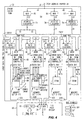
- FIG. 1 a simplified block diagram 1 of a Non-Volatile Memory Test System constructed in accordance with the principles of the invention.
- the system shown can simultaneously test, with as many as sixty-four test points each, up to thirty-six individual DUT's (Devices Under Test) at one time, with provisions for reconfiguration to allow elements of a collection of test resources to be bonded together to test DUT's having more than sixty-four test points.
- These test points may be locations on a portion of an integrated circuit wafer that has not yet been diced and packaged, or they might be the pins of a packaged part.
- test point refers to an electrical location where a signal may be applied (e.g., power supplies , clocks, data inputs) or where a signal can be measured (e.g., a data output).
- a signal may be applied (e.g., power supplies , clocks, data inputs) or where a signal can be measured (e.g., a data output).
- channels We shall follow the industry custom of referring to the test points as "channels”.
- the "collection of test resources to be bonded together” referred to above may be understood as being as many as thirty-six test sites, where each test site includes a Test Site Controller (4), a (sixty-four channel) DUT Tester (6) and a (sixty-four channel) collection of Pin Electronics (9) that makes actual electrical connection to a DUT (14).
- Test Site #1 (as it appears in Figure 1) forms or operates as a "Single Site Test Station”.
- two (or more) Test Sites are "bonded" together to function as one larger equivalent Test Site having one hundred and twenty-eight channels. Accordingly, and again in reference to an example shown in Figure 1, we say that Test Sites #35 and #36 form a "two-Site Test Station".
- test Site An entire Test Site is needed to test a single DUT, or that a single Test Site can test but a single DUT.
- a wafer had two (probably, but not necessarily, adjacent) dies, the sum of whose test channel requirements were sixty-four channels or less. Both DUT's can be tested by a single Test Site. What makes this possible is the general purpose programmability of each Test Site.
- a test program executed by the Test Site may be written such that one part of the Test Site's resources is used to test one of the DUT's while another part is used to test the other DUT.
- Test Stations need not equal the number of Test Sites. In the past, the numbers could be different because Test Sites were split to create more Test Stations (DUT's not complex enough to consume an entire Test Site). Now, however, the difference may also be due to Test Sites having been bonded together to form multi-site Test Stations (DUT's too complex for a single Test Site).
- a Test System Controller 2 is connected by a System Bus 3 to as many as thirty-six Test Site Controllers whose names end in the suffixes #1 through #36 (4a-4z). (It is true that subscripts a-z only go from one to twenty-six, and not to thirty-six. But this minor deception seems preferable over numerical subscripts on numerical reference characters, which would be potentially very confusing.)
- the Test System Controller 2 is a computer (e.g., a PC running NT) executing a suitable Test System Control Program pertaining to the task of testing non-volatile memories.
- the Test System Control Program represents the highest level of abstraction in a hierarchical division of labor (and of complexity) for accomplishing the desired testing.
- Test System Controller determines which programs are being run by the different Test Sites, as well as overseeing a robotics system (not shown) that moves the test probes and DUT's as needed.
- Test System Controller 2 may function in ways that support the notion that some Test Sites are programmed to perform as single-site Test Stations, while others are bonded together to form multi-site Test Stations. Clearly, in such circumstances there are different parts being tested, and it is most desirable that different tests be used for the different parts. Likewise, there is no requirement that all single-site Test Stations be testing the same style of part, nor is there any such requirement for multi-site Test Stations.
- the Test System Controller 2 is programmed to issue the commands to accomplish the needed Test Site bonding and then to invoke the appropriate test programs for the various Test Stations in use.
- the Test System Controller 2 also receives information about results obtained from the tests, so that it may take the appropriate action for discarding the bad part and so that it may maintain logs for the various analyses that may be used to control, say, production processes in a factory setting.
- the Test System itself is a fairly large and complex system, and it is common for it to use a robotics subsystem to load wafers onto a stage that then sequentially positions one or more future dies under probes connected to the Pin Electronics 9, whereupon those future dies (the wafer has not yet been diced) are tested.
- the Test System can also be used to test packaged parts that have been loaded onto a suitable carrier. There will be (as is explained below), at least one Test Site Controller associated with each Test Station in use, regardless of how many Test Sites are used to form that Test Station, or of how many Test Stations are on a Test Site.
- a Test Site Controller is an embedded system that may be an i960 processor from Intel with thirty-six to sixty-four MB of combined program and data memory running a proprietary operating system called VOS (VersaTest O/S), which was also used in earlier products for testing non-volatile memories (e.g., the Agilent V1300 or V3300).
- VOS VeryTest O/S
- Test System Controller 2 tells Test Site Controller #1 (4a) (which is an embedded [computer] system) to run the associated test program, say, TEST_WHIZ_13. If that program is already available within Test Site Controller #1's environment, then it is simply executed. If not, then it is supplied by the Test System Controller 2.
- Test Site Controller #1 (4a) (which is an embedded [computer] system) to run the associated test program, say, TEST_WHIZ_13. If that program is already available within Test Site Controller #1's environment, then it is simply executed. If not, then it is supplied by the Test System Controller 2.
- the program TEST_WHIZ_13 could be entirely self-contained. But if it were, then it would almost certainly be rather large, and it may be difficult for the processor of the embedded system within the Test Site Controller 4a to run fast enough to produce the tests at the desired speed, or even at a rate that is uniform from one DUT memory cycle to the next. Accordingly, low level subroutine type activities that generate sequences of address and associated data that is to be written or is expected from a read operation, are generated as needed by a programmable algorithmic mechanism located in the DUT Tester 6, but that operates in synchrony with the program being executed by the embedded system in the Test Site Controller 4.
- the Test System Controller 2 equips a Test Site Controller with a test program it also supplies the associated DUT Tester with appropriate low level implementation routines (perhaps specific to the memory being tested) needed to accomplish the overall activity described or needed by the programming for the Test Site Controller.
- the low level implementation routines are termed "patterns", and they are generally named (just as functions and variables in high level programming languages have names).
- Each Test Site Controller #n (4) is coupled to its associated DUT Tester #n (6) by a Site Test Bus #n (5).
- the Test Site Controller uses the Site Test Bus 5 to both control the operation of the DUT Tester and receive therefrom information about test outcomes.
- the DUT Tester is capable of generating at high speed the various DUT memory cycles that are involved in the test regimen, and it decides if the results of a Read memory cycle are as expected. In essence, it responds to commands or operation codes ("named patterns") sent from the Test Site Controller by initiating corresponding useful sequences of Read and Write DUT memory cycles (i.e., it executes the corresponding patterns).
- the output of the DUT Tester 6 is stimulus information that is to be applied to the DUT, and it also accepts response information therefrom.
- This stimulus/response information 7a passes between the DUT Tester 6a and a Pin Electronics #1 assembly 9a.
- the Pin Electronics assembly 9a supports up to sixty-four probes that can be applied to the DUT 14.
- the above-mentioned stimulus information is just a sequence of parallel bit patterns (i.e., a sequence of "transmit vectors" and expected “receive vectors") expressed according to the voltage levels of some family of logic devices used in the DUT Tester.
- the individual bits are correct as to their timing and edge placement, but in addition to the mapping they may also need voltage level shifting before they can be applied to the DUT.
- a response that originates in the DUT subsequent to a stimulus may need buffering and (reverse) level shifting before it can be considered suitable for being fed back to the DUT Tester.
- Each card cage has, besides power supplies and water cooling (fans can be a source of contamination in a clean room environment), a mother board, a front plane and a back plane.
- Into each card cage can be placed up to nine assemblies.
- Each assembly includes a Test Site Controller, DUT Tester and Pin Electronics. We shall be describing the general outlines of how Test Site Controllers are bonded together, which will involve some busses used to create daisy chains.
- the daisy chains are high performance pathways for command and control information, and that if they were not, then we could not expect a master/slave combination (multi-site Test Station) to operate as fast as a single Test Site does.
- the various DSY do not leave their respective card cages. The effect of this decision is to place some limits on which Test Sites (and thus also how many) can be bonded together. In principle, there is no fundamental need for this limitation, nor is there a genuine lack of technical practicality involved (it could be done); it is simply felt that, since there are already nine Test Sites in a card cage, extending the DSY's adds significant cost for relatively little additional benefit.
- Test Site Controllers 4a-4z that can populate the four card cages, each with nine Test Site Controllers. Let's denote them as 4a-4f, 4g-4m, 4n-4t and 4u-4z. (Never minding, as explained earlier, that these are nominally only twenty-six subscripts -- the reader is invited to imagine that there are another ten subscript symbols in there, someplace.)
- a CMD/DAT DSY 17a (Command & Data Daisy Chain) interconnects the Test Site Controller 4a-4f that are in one card cage, while a different CMD/DAT DSY 17b interconnects the Test Site Controllers 4g-4m in another card cage.
- the CMD/DAT DSY 17a-d that we have been discussing exist between the various Test Site Controllers 4a-4z.
- the synchronization and error information conveyed by the SYNC/ERR DSY 18 allows DUT Testers to function in unison.
- These two daisy chains (17 and 18) carry slightly different types of information, but each exists as part of the same general mechanism for bonding one or more Test Sites together into a Test Station.
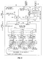
- Figure 2 is a simplified block diagram expansion of the DUT tester 6 of Figure 1, of which there may be as many as thirty-six. It is sufficient at present to describe only one instance thereof. A glance at Figure 2 will show that it is a fairly well populated with stuff; especially so for a "simplified" block diagram. Some of what is in the DUT Tester 6 and represented in the block diagram is functionally quite complicated, and is not available in "off the shelf' form. It is appropriate here to make two points. First, the primary purpose of including Figure 2 is to describe the basic properties of an important operational environment within the overall Non-Volatile Memory Test System 1.
- the major input to the DUT Tester 6 is an instance of the Test Site Bus 5, which originates from a Test Site Controller 4 that is associated with the instance of the DUT Tester 6 that is of interest.
- the Test Site Bus 5 is coupled to a Micro-Controller Sequencer 19, which may be likened to a special purpose microprocessor. It fetches instructions from a program stored in a program memory, which may be either internal to the Micro-Controller Sequencer 6 (PGM SRAM 20) or external thereto (EXT. DRAM 21).
- the instruction word executed by the Micro-Controller Sequencer 19 is fairly wide: two hundred and eight bits. It consists of thirteen sixteen-bit fields. These fields often represent fetched instruction information for mechanisms that are outside the Micro-Controller Sequencer proper. Such fields are dedicated to their associated mechanisms.
- One set of ALU INSTRUCTIONS 22 are applied to a collection of eight sixteen-bit ALU's 24, while others are disbursed to various other mechanisms distributed throughout the DUT Tester. This latter situation is represented by the lines and legend "VARIOUS CONTROL VALUES & INSTRUCTIONS" 42.
- the eight sixteen-bit ALU's (24) each have a conventional repertoire of arithmetic instructions built around associated sixteen-bit result registers (each ALU has several other registers, too). Three of these result registers and their associated ALU's are for generating X, Y and Z address components 27 that are variously combined into a complete address to supplied to the DUT. Two more of the eight ALU/registers (DH & DL) are provided to assist in the algorithmic creation of thirty-two bit data patterns 28 that are divided between a most significant portion (DH) and a least significant portion (DL).
- a final three ALU/registers (A, B, C) are used as counters and contribute to the production of various PROGRAM CONTROL FLAGS 25 that assist with program control and branching on completion of some programmatically specified number of iterations or other numerical condition.
- PROGRAM CONTROL FLAGS 25 are sent back to the Micro-Controller Sequencer 19, where they affect the value of the instruction fetch address in ways familiar to those who understand about microprocessors.
- OTHER FLAGS 55 that also can be used to effect program branching. These originate with various ones of the other mechanisms within the DUT Tester 6 that are controlled by the different fields of the fetched instruction word.
- One specific additional flag is expressly shown as a separate item: VEC_FIFO_FULL 26. In another drawing having somewhat less detail it might be lumped in along with the OTHER FLAGS 55. We have separated it out to assist in explaining one aspect of the operation of the Micro-Controller Sequencer 19.
- What VEC_FIFO_FULL does is to (temporarily) halt further program execution by the Micro-Controller Sequencer 19.
- part of the baggage that accompanies a vector as it moves toward being applied to the DUT is information concerning the rate of eventual vector application, or, each vector's duration.
- the rate of vector application to the DUT need not be constant, and in particular, a Group of vectors may take longer to apply than they did to generate.
- the Micro-Controller Sequencer simply executes programming at its maximum rate.
- VEC_FIFO_FULL is used to prevent overrunning the limited number of stages in the pipeline, by causing a temporary cessation in the production of new vectors at the head end of the pipe.
- a look-up table could be implemented that could map any applied address into another, arbitrarily selected, forty-eight bit value which could then be used as a replacement address.
- the reason that such address mapping is desirable is that the X, Y and Z address components generally have useful meaning in the context of a particular DUT's internal architecture, which is most likely not implemented with one big linear decoder.
- the notions of rows, columns and layers, block or pages may be very useful to the Test Engineer, and failures that occur in locations that are physically close together may involve corresponding closeness in their X, Y and Z addresses.
- the Address Mapper 29 is constructed of a fairly large number of interconnected multiplexers. It cannot implement the completely arbitrary look-up table behavior of a fully populated memory decode scheme as was temporarily assumed above for purposes of explanation. It can however, rearrange sub-fields of the X, Y and Z address components as needed, particularly since there is yet another mechanism that will do the paring down from forty-eight bits to the actual number needed.
- the Address Mapper 29 also contains three sixteen bit (address) look-up tables that allow it to perform limited arbitrary mapping within local ranges.
- the mapped address output 30 of the Address Mapper 29 is applied as an address to an Aux RAM 31 and to an Error Catch RAM 32, which, while having separate functions, may nevertheless be implemented selectable partitions in one larger overall RAM.
- the mapped address output 30 is also applied as one input to an Addr. Bit Select circuit 37, which is described below.
- the Aux RAM 31 Its function is to retain data patterns 33 and addresses 34 that can be applied to the DUT. These are logically separate outputs from the Aux RAM 31, since they are treated somewhat differently and used in different places.
- the AUX RAM 31 is not a dual "port memory", but is preferably of several Banks whose outputs are applied to MUX's.) In keeping with this, it may be that Stored Data 33 is kept in one Bank or range of addresses of the Aux RAM 31, while Stored Addresses 34 are kept in another. Also, we have not shown an explicit mechanism for writing to the Aux RAM 31. That is accomplished by an addressed bus operation initiated by a Test Site Controller 4 at the behest of the program it is executing. (There is an "under the floorboards,” as it were, "utility services” bus called the "Ring Bus” [not shown -- as it would clutter the drawing enormous] that goes to just about everything in Figure 2.)
- the Error Catch RAM 32 is addressed by the same address that is applied to the Aux RAM 31, and it either stores or retrieves information about errors, which operations are performed in conjunction with a Post Decode Circuit, to be discussed later.
- paths 33 and 34 from the Aux RAM 31 paths 61 (into the Error Catch RAM) and 62 (from the Error Catch RAM) are preferably MUX'ed outputs from a multi-Bank memory (the Error Catch RAM 32), in accordance with configuration information distributed by the Ring Bus (not shown).
- the Data MUX 35 has as inputs the STORED DATA output 33 from the Aux RAM 31 as well as data 28 from the registers DH and DL in the collection 24 of ALU's.
- the Data MUX 35 selects which of these inputs (28, 32) to present as its output 38, which is then applied as one of two vector components to a Transmit Vector Mapper / Serializer / Receive Vector Compare Data Circuit 40 (the other component is the output 39 of the Addr. Bit Select circuit 37).
- Data MUX 35 performs this selection in accordance with values 36 stored in PGM SRAM 20.
- Circuit 40 can perform three functions: assemble vector components (38, 39) into an ordered logical representation an entire vector that is to be applied (transmitted) to the DUT; apply an arbitrary dynamic correspondence (mapping) between the ordered bits of the logical representation of the transmit vector and the actual physical channel number of the Pin Electronics (i.e., which probe tip) will contact the DUT on behalf of that signal (i.e., that bit in the vector); and, cooperate with the compiler in the division of an entire logical vector into pieces to be applied separately and in order (serialization) for DUT's that admit of such a thing.
- the output of Circuit 40 is an up to sixty-four bit vector 44 that is applied to a Vector FIFO 45, which when full generates the signal VEC_FIFO_FULL 26, whose meaning and use was discussed above.
- the vector at the top of the Vector FIFO 45 is removed therefrom upon receipt of a signal VEC_FIFO_UNLOAD 47 that originates at a Period Generator 49 (to be discussed shortly).
- Such removed vectors (46) are applied to a Timing / Formatting & Comparison circuit 52 that is connected to the DUT via the associated instance of Pin Electronics 9. That is, each instance of Pin Electronics 9 receives Transmitted & Received Vectors 7 and Pin Electronics configuration information 8 from its associated Timing / Formatting & Comparison circuit 52.
- the Timing / Formatting & Comparison circuit 52 has an Internal SRAM 54 addressed by the same Instruction Address ("A" in the small circle) as is the Program SRAM 20 of the Micro-Controller Sequencer 19. (An External DRAM 53 may be used in place of the Internal SRAM 54.)
- the Internal SRAM 54 (or external DRAM 53) assists in the production of Drive and Comparison cycles.
- Drive cycles apply a transmit vector to the DUT.
- Comparison cycles receive a vector presented by the DUT and examine it to determine if it matches previously supplied comparison data. Both Drive and Comparison cycles are adjustable as to their duration, whether and when a load is applied, and when data is latched or strobed.
- the comparison produces a sixty-four bit value 56 that is applied to a Receive Vector Reverse Mapper / Deserializer 57, whose function may be considered to be the logical inverse of circuit 40.
- the operation of circuit 57 is controlled by an SRAM 58 that corresponds to the control of circuit 40 by SRAM 41.
- the output 59 of circuit 57 is applied to the Post Decode circuit 60.
- the Post Decode circuit 60 can inspect via programmatic criteria both incoming error information 59 and (previously) stored error information 60 (stored in Error Catch RAM) to produce condensed and more readily interpretable error information which may then by stored back into the Error Catch RAM 32 via path 61.
- An example would be to create a count of how many times there was an error within a particular range of addresses, which information may be useful in deciding when to attempt to engage in on-chip repair by enabling substitute circuits.
- T_SEL 43 is member of the Various Control Values & Instructions 42 that are represented by the different fields within the fetched instruction. As an eight bit value it can represent or encode two hundred and fifty-six different things. In this case those "things" are twenty-eight bit values stored in the Timing SRAM 51 and that are addressed by T_SEL. Each addressed twenty-eight bit value (23) specifies a desired duration with a 19.5 picosecond resolution.
- the sequence of accessed twenty-eight bit duration values (23) is stored in a Period FIFO 50 so that the individual members of that sequence will be retrieved and applied in synchronism with the retrieval of their intended corresponding vector, which is stored in the Vector FIFO 45.
- a coarse timing value field in the oldest entry in the FIFO 50 conveys duration information with a resolution of 5 nsec, and produces therefrom a signal VEC_FIFO_UNLOAD 47 that transfers the next transmit vector from the Vector FIFO 45 to the Timing / Formatting & Comparison circuit 52.
- a companion signal TIMING REMAINDER 48 is also applied to circuit 52. It is there that the ultimate resolution to 19.5 picoseconds is accomplished.
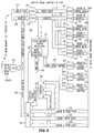
- FIG 3 is a simplified block diagram 64 of the ECR 32 in the block diagram of Figure 2. It receives a forty-eight bit mapped address 30 from the Address Mapper 29, which is applied to various Address Classifiers 77, 78 and 79.
- the Address Classifiers are associated with Memory Sets 73 - 76, which are each complete memory mechanisms that can individually perform associated ECR functions. Two of these Memory Sets (73, 74) are of external DRAM, while two are of internal SRAM. The two external DRAM Memory Sets will always have the same Address Classifier function in effect, and thus share one common Address Classifier 77.
- the internal SRAM Memory Sets 75 and 76 each have their own associated Address Classifiers, 78 and 79, respectively.
- Address Classifiers may be conventional and can change the address according to principles and for purposes that are well known in the art. They are shown here for the sake of completeness and to promote compatibility between this application and an expected related application. While the Address Classifiers are there to perform a useful function, they may be safely ignored herein by simply assuming that they perform no change to the address.
- Each Memory Set includes a Memory Set Controller; the external DRAM Memory Sets 73 and 74 have DRAM Memory Set Controllers 65 and 66, respectively, while the internal SRAM Memory Sets 75 and 76 have respective SRAM Memory Set Controllers 67 and 68.
- the address for memory transactions directed to any of these Memory Sets arrives at the associated Memory Set Controller from the respectively associated Address Classifier.
- a DUT Error Data 61 arriving from the Post Decode circuit 60 and that is to be written into the ECR is first applied to Data Classifiers 80-83, one of which is associated with each Memory Set.
- the function of the Data Classifiers is not presently of interest, and we show them here principally for the sake of completeness, and to promote compatibility between this application and an expected related application.
- the Data Classifiers 80-83 may be safely ignored herein by assuming that they simply pass the data through without modification.
- the Address and Data Classifiers represent high speed paths for addresses and data, respectively, which are intended to operate at the highest speeds necessary.
- the Ring Bus (not yet shown) provides another way to convey addresses and data to the Memory Sets.
- DRAM Memory Set Controllers 73 and 74 are respectively coupled to external DRAM's 69 and 70, while SRAM Memory Set Controllers 75 and 76 are respectively coupled to internal SRAM's 71 and 72.
- DRAM Memory Set Controllers 73 and 74 are respectively coupled to external DRAM's 69 and 70
- SRAM Memory Set Controllers 75 and 76 are respectively coupled to internal SRAM's 71 and 72.
- SRAM Memory Set Controllers 75 and 76 are respectively coupled to internal SRAM's 71 and 72.
- SRAM Memory Set Controllers 75 and 76 are respectively coupled to internal SRAM's 71 and 72.
- the DRAM Memory Set Controllers 65 and 66 are configurable, perform different types of memory transactions, and are not altogether the same as the simpler SRAM Memory Set Controllers 67 and 68.
- Figure 3 does not show the structure that provides this flexibility; for now let's just say that each Memory Set Controller is connected to the Ring Bus (not yet shown), from which it is instructed in the particular mode of operation and configuration that are desired. Some of these modes involve how data is stored, and some have to do with getting it back out again. We shall be principally interested in the modes and configurations of the DRAM Memory Sets. To conclude, then, note that each Memory Set does have an associated Data Out (62A-D) which is sent to the Post Decode Mechanism 60 for further processing.
- 62A-D Data Out
- FIG 4 is a more detailed block diagram 84 of the ECR 32 that was described in conjunction with Figure 3. It is much the same, and similar elements have been designated with common reference numerals. For our present purposes it is sufficient to point out the incremental differences present in Figure 4. Specifically, note that each ofthe Address Classifiers (78-79)is preceded by an associated MUX (85-87). These MUX'es assist in the process of address refinement, and especially in getting the size ofthe address down from forty-eight bits to thirty-two.
- Memory Set 0 (73) has three Groups 88, 89 and 90
- Memory Set 1 (74) has Groups 91, 92 and 93.
- Groups multiplexing
- Each of these Groups is made up of four Banks (four instances of an address space), for which the memory operations can be interleaved in accordance with principles and practices understood in the art.
- the type of DRAM preferred for use at present is SDRAM, which implies a particular strategy for interleaving. It will be appreciated that there are other types of DRAM and that other mechanisms for interleaving are possible, besides the one to be described below.
- the Groups are addressable instead of being selected automatically.
- extra address bits for the Group are used to select the hardware path.
- an address specifies a Group and a Bank address within that Group of interleaved Banks.
- both multiplexing and interleaving are turned off, and and address has Group selection bits, Bank selection bits and within-Bank address bits.
- additional addressing bits are used to specify a field within the entire word that is the target of the memory transaction.
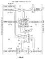
- FIG. 5 is a simplified block diagram 96 of a DRAM Memory Set Controller (65, 66) appearing in Figures 3 and 4. It receives as input a CLASSIFIED ADDRESS 106, mode and configuration information from the Ring Bus 85, and ERROR DATA IN 105 from the associated Data Classifier. As before, it produces DATA OUT (62A/B).
- CLASSIFIED ADDRESS 106 receives as input a CLASSIFIED ADDRESS 106, mode and configuration information from the Ring Bus 85, and ERROR DATA IN 105 from the associated Data Classifier. As before, it produces DATA OUT (62A/B).
- Ring Bus 85 there is a Bus Interface 97 that couples the Ring Bus to the DRAM Memory Set Controller, and via that interface DATA FROM RING BUS 99 and ADDRESS FROM RING BUS 100 are available.
- a MUX 104 selects whether ERROR DATA IN 105 or DATA FROM RING BUS 99 is sent forward as data 107, thence to be applied to the DATA IN terminal of a Master DRAM Controller 109.
- a MUX 103 selects between CLASSIFIED ADDRESS 106 and ADDRESS FROM RING BUS 100 to produce the address 108 that is applied to the ADDRESS terminal of the Master DRAM Controller.
- a collection of one or more registers 98 whose content is set by traffic on the Ring Bus produces control signals 101 and 102 that indicate the selections to be made by MUX'es 103 and 104, respectively.
- a principal function of the DRAM Memory Set Controller is the allocation or distribution of the various memory transactions among the three Groups. In a high speed mode of operation it performs this allocation in a round robin fashion using (the equivalent of) a 1:3 MUX 125.
- the MUX 125 is shown as a dotted line, since it will become clear that, while there could indeed be a MUX, in the present preferred embodiment, there is not an actual MUX at that location. Instead, and as will become clear in conjunction with Figure 6, there are multiple instances of addressable data sources under the control of a sophisticated rule following mechanism (a state machine).
- each SDRAM Slave Controller has as its Group a collection of four Banks of SDRAM.
- the SDRAM Controller 110 for Group 0 is coupled to Banks 113, 114, 115 and 116.
- Group 1 has Banks 117-120, while Group 2 has Banks 121-124. The result is a total of twelve Banks for each DRAM Memory Set, of which there are two.
- the SDRAM of each Group can be arranged to operate in several modes or configurations. When configured for random addressing operation at the highest speed, multiplexing between Groups happens at the highest rate, and consecutive memory operations are always and automatically sent to the next Group in a cyclic sequence thereof. Within a Group, memory operations are interleaved to evenly distribute them among the four Banks. A regular cyclic sequence is preferred here, too. The interleaving produces a four-fold increase in speed, which, when combined with a three fold increase provided by the multiplexing, is an increase in speed by a factor of twelve. This manner of operation treats each Bank as a full address space, with no attempt to control ahead of time which of the twelve Banks is the target for a particular memory transaction.
- the multiplexing and interleaving schemes are, of course, limited to the DRAM Memory Sets (the SRAM Memory Sets go fast to begin with). This does not mean, however, that these same abilities or modes of operation cannot be supported by the SRAM Memory Sets.
- memory transactions that can be directed to one Memory Set can be directed to any other, subject only to size constraints.
- An SRAM Memory Set will honor any style of operation that a DRAM Memory Set would.
- the difference is how the Memory Set controller internally implements the desired transaction. for example, in the case of an Analysis Read (compose) an SRAM Memory Set need not bother beyond doing the simple read, since its data is already composed in the first place.
- PATTERN WRITE OWW ALL (1, 4, 12) BANKS W 1/1 W 4/4 W 12/12 AND DATA PATTERN READ ANR ALL (1, 4, 12) BANKS R 1/1 R 4/4 R 12/12 H/S ADDR.
- PATTERN WRITE OLW NEXT (1, 4, 12) BANKS W 1/1 W 1/4 W 1/12 AND DATA PATTERN READ BMR NEXT (1, 4, 12) BANKS R 1/1 R 1/4 R 1/12
- FIG. 6 is a block diagram 126 of the Master DRAM Controller 109 that appears in Figure 5.
- An applied WRITE DATA 107 and ADDRESS 108 from the associated Memory Set Controller are coupled to respective FIFO's 127 and 128.
- the WRITE DATA 131 is applied to further FIFO's that are associated with the different Groups. These are FIFO's 137, 139 and 141.
- Their outputs (166, 168 and 170) are the actual write data busses for Group 0 through Group 2, respectively.
- the output ofFIFO 128 is applied to FIFO's 138, 140 and 142, whose outputs in turn become the address busses (167, 169 and 171) for those Groups.
- the Master DRAM Controller 109 includes a State Machine 193 that is coupled to ADDRESS 132 as well as to the Ring Bus 85. Among other things, various Mode Control Registers 130 can be set up to indicate the desired mode and configuration.
- the State Machine 193 is also responsible for selecting what Group is to receive the next memory transaction, in accordance with the mode and configuration in effect. That is, it will either honor a field of Group selection bits in an incoming address or it will automatically select the next Group. To produce a memory operation for a Group it issues the appropriate GROUP CYCLE CONTROL signals 133.
- the MUX 148 selects between one of the individual GROUP READ DATA and the composed version of data for that address (COMPOSED GROUP READ DATA 147).
- the astute reader will note that if a compose operation is underway, then each of the GROUP READ DATA busses will need to provide four words of data, which implies the need for four consecutive READ's (involving the ADDRESS FIFO's 138, 140 and 142 and the CYCLE CONTROL FIFO's 143, 144 and 145).
- Figure 7 is a block diagram of the COMPOSER circuit 146. Recall that its function is to read from the same address for all twelve Banks across three Groups (data stored as R100), or for all four Banks of one Group (data stored as R33), and merge the contents into one word, preserving zeros in a bit position, even though other words in the twelve (four) might have a one in that bit position To this end, the Master DRAM Controller of Figure 6 will arrange that all four Banks at each appropriate Group will be read, using the same address.
- the scheme as described to this point works provided the latches are set before composition begins. That, however, takes time, and it is desirable to have the scheme work regardless of the initial state of the latches 156 through 157.
- This is arranged by having a FIRST CYCLE signal 155 applied as an input to two-input OR gates (153, 154) that also receive the latch output as the other input.
- the outputs ofthe OR gates 153 through 154 are applied as the "re-circulating" inputs to the AND gates 151 through 152.
- the FIRST CYCLE signal 155 is generated by the State Machine 193 in Master DRAM Controller 109 and is TRUE only during the read of the first Banks of each Group.
- the thirty-two latches 156 through 157 contain the COMPOSED GROUP READ DATA 147, which is then used by the Master DRAM Controller 109 of Figure 6 in the manner previously indicated.
- An additional piece of information is needed to appreciate how this same mechanism works for R33 operation.
- An unused or inactive GROUP N READ DATA BUS (would be two of 134, 135 and 136 during R33) appears as all one's. This allows the same mechanism that works for R100 to also function correctly for R33.
- FIG 8 is a block diagram 158 of a Slave SDRAM Controller (110, 111 and 112 of Fig. 5).
- a central element of the Slave SDRAM Controller is a State Machine 161, which includes some control registers 180 that are set by coupling to the Ring Bus 85.
- a GROUP N ADDRESS (will be one of 167, 169 or 171) is applied to a FIFO 159, from whence it is captured by a register 160 and is also coupled to the State Machine 161. (The value for N will be understood to be zero, one or two.) From the register 160 the GROUP N ADDRESS 170 is applied to the SDRAM chips that make up the Group of interest.
- the State Machine 161 also receives GROUP CYCLE CONTROL information (will be one of 172, 173 or 174) from the Master SDRAM Controller 109. From this, in addition to knowing what mode of operation and configuration is in effect, the State Machine 161 can create the appropriate sequence of SDRAM control signals 176 (includes RAS, CAS, Chip Enable, etc.) for the Group of interest. It is the State Machine 161 that actually accomplishes the interleaving by the way it generates those control signals 176.
- the State Machine 161 also contains a refresh timer (not explicitly shown) that, when it times out (typically after about forty microseconds), stalls further operations from the outside while some installment of refresh is performed. Refresh is performed a row at a time, for all columns in the row. Each next installment of refresh does the next row.
- a refresh timer (not explicitly shown) that, when it times out (typically after about forty microseconds), stalls further operations from the outside while some installment of refresh is performed. Refresh is performed a row at a time, for all columns in the row. Each next installment of refresh does the next row.
- the Slave DRAM Controller and its outer environment are pipelined (all those FIFO's) and the native rate of Slave SDRAM Controller operation is 143 MHz, so that the approximately 7% of its time devoted to refresh still leaves it time to respond at an aggregate 100 MHz rate.
- the GROUP N WRITE DATA (will be one of 166, 168 or 170) is applied to a FIFO 162, whose output is thence applied as an input to a (2:1) X 32 MUX 163.
- the output of the MUX 163 is coupled to the signals that are the GROUP N DATA 178 for the Group of interest. On these lines 178 will appear both data to be written and data that has been read. Data that is to be written comes from MUX 163, and originates either with the GROUP N WRITE DATA via FIFO 162 or from data that has just been read and stored in a register 164. Path 179 represents this latter case, which occurs when read-modify-write style operation is to be performed.
- Table II identifies the meanings of various symbols used Tables V - X. That is, it tells what interpretation is to be given to the various bit positions in an address under different ECR modes of operation and configuration.
- the addressing schemes set out in Tables V - X should be thought of as being what is applied to the State Machines in the Master and Slave Memory Controllers, rather than directly to the memory parts themselves.
- Table III indicates various memory parts with which the ECR can be populated, and tells something of their expected organization.
- these are parts (182 - 185) with sixteen data bits, so that to get a full width word (thirty-two bits) two parts will be addressed in tandem (182 & 183, 184 & 185), with their output bits conjoined into one large field 178.
- each part has four Banks, each of which implements a separate instance of the address space of the part (exploited during R100 and R33 operation).
- An alternative view is to construe the associated two Bank Select bits as further address bits, which is useful for L100 operation.
- CHIP SELECT signals function, from an addressing point of view, as if they were equivalent to row address bits.
- parts 182 and 184 combine to provide storage for half of the thirty-two bits of data, while parts 183 and 185 store the other half. So if the parts were 512Mbit parts, the arrangement shown is a 16M address at each of four banks by thirty-two bit data word memory.
- Table IV is useful in appreciating relationships that may exist between the logic of the test program (focused on DUT architecture and internal organization) and the modes and configurations for the ECR and its Memory Sets.
- An important concept to bear in mind is that both the DUT and the ECR can construe the same ordered sequence of bits as an address, even though they each have a very different internal organization and manner of operation.
- Table IV shows only two of a great many different possible DUT related interpretations of thirty-two ordered address bits.
- Tables IV - IX show ECR related interpretations of those same thirty-two address bits, and the two interpretations have very little to do with each other.
- the principal thing that the writer of a test program wants is the ability to have an address in the ECR that corresponds to the address applied to the DUT, with the knowledge that "he” (i.e., the memory tester under programmatic control) can write data to the ECR and later get it back again for analysis.
- the test engineer searches for ways to capture meaning related to DUT architecture.
- the ECR addressing bits relate to its internal operation, regardless of any newfangled DUT.
- Table V shows how 512M SDRAM parts are addressed when they are configured as part of a single Memory Set.
- the word width is a full thirty-two bits (bottom row of the table). This can happen under two different modes of operation: R100 (the full disaster of random addressing at 100 MHz using multiplexing and interleaving) and R33 (33 MHz random addressing with interleaving but without multiplexing).
- R100 the full disaster of random addressing at 100 MHz using multiplexing and interleaving
- R33 33 MHz random addressing with interleaving but without multiplexing.
- the native address space of 8M is provided by the thirteen R's and the ten C's. That becomes 16M of address space (at each of four Banks) when the chip enable bit E is included.
- the Master DRAM Controller's State Machine simply directs the next memory transaction to the next Group's bus, without need of any addressing bits that correspond to the Group. This follows directly from each Group having its own bus; addresses on one bus are in a totally separate instance of an address space from those on another bus. Hence the footnote in Table V.
- the addressing scheme shown in Table V also supports the Narrow Word configurations. Again, it is a case of supplying additional addressability to account for the subdivision into small fields within the full word. These are the F bits, which range from none (full thirty-two bit word) to five (thirty-two one-bit fields). To implement this mode of operation is another reason why the State Machine 161 of the Slave SDRAM Controller receives the GROUP N ADDRESS. It is also a reason why MUX 163 and data path 179 (see Figure 8) are provided. It will be appreciated that the F bits do not go to the DRAM parts themselves; they get addressed as if for a full thirty-two bit word. It is the Slave SDRAM Controller that provides this additional Narrow Word capability, and the F bits disappear at the SDRAM controller, to be replaced by the appropriate Controller behavior.
- Table VI is similar to Table V. Whereas Table V dealt with Groups that may or may not be stacked, Table VI deals with Memory Sets that are stacked. It uses the 512M part as an example; cut-down versions of Table VI exist for the smaller memory parts (as do cut-down versions of Table V, too). These other tables have been omitted for the sake of brevity.
- To stack two Memory Sets we need to have them configured each the same as the other, and provide one extra bit (the M bit) to double the address space, so that it matches two Memory Sets instead of just one. Who controls this extra bit is the test program. Who responds to it is the Master DRAM Controller (which is why its State Machine 193 of Figure 6 is coupled to the ADDRESS 132).
- the M bit disappears as an addressing bit at that point, to be replaced by the presence or absence of memory activity, depending upon if the Memory Set having that instance of State Machine 193 is the addressed Memory Set.
- Tables VII and VIII are essentially derivable from what has been discussed to this point. That is, the top line of Table VII is the same as the top line of Table V, and the top line of Table VIII is the same as the bottom line of Table V. The difference is that the vertical axes of Tables VI and VII are part size, while the vertical axis of Table IV is Narrow Word Mode.
- Tables IX and X deal with the L100 configuration. Recall that this is the "linear" or Locality mode of addressing (minimal changes in row address). Here there is no multiplexing, and no interleaving. Where we used to have twelve separate instances of an address space we now have one, but it is twelve times as deep. This raises the need for four more address bits to apply to the Master DRAM and Slave SDRAM Memory Controllers. Those extra bits are GG and BB bits shown in both tables. As before, these bits disappear into the Controllers, as it were, to be replaced by the corresponding functionality, all made possible by smart State Machines and separate busses for the collections of memory that are the Groups. The difference between the two tables is the M bit, which operates as previously described in connection with Table VI. Note also that L100 operation excludes the notion of the Narrow Word mode: there are not enough address bits at the system level to support it.
- Composition is also possible in the R33 mode of operation. The difference is minor, in that the two non-addressed Groups need to be "shut down" during the four reads and writes needed to step through the interleaving. During the reads the two non-addressed ones of the GROUP N READ DATA BUSSES 134, 135 and 136 need to have all ones present while the addressed one performs as usual. This will produce the appropriate result in the COMPOSER 146, which is then written back into the Group that was composed. Only the four Banks of the Group are to be written to, as the corresponding addresses in the other Groups are really quite different locations in the address space in use (stacked Groups).
- the State Machine in the Master DRAM Controller can arrange all this by determining which Groups get GROUP CYCLE CONTROL information over their associated busses. It is also assumed that the GROUP N READ DATA busses will present ones when inactive, or that they can be otherwise made to go high. If that is not the case then additional control over the inputs to the AND gates 151 through 154 will be needed to mask out the bits from Groups that are not to participate in the composition.
- Tables XI and XII are conventional.
- these SDRAM parts have a data bus (D) that is separate from the address/control bus (AC).
- the precharge includes Bank selection.
- the fundamental operational cycle is p (precharge), a (select row) and then either r (read) or w (write), both of which include a column selection, followed by data (i or o) on D.
- the lines labeled B0 - B3 are not separate collections of electrical signals. Anything shown on these lines of the Tables actually happens on the data bus (D) or on the address/control bus (C). We show it as we have to separate signal traffic for clarity while at the same time keeping such traffic in alignment as to time and also avoiding a cumbersome use of subscripts.
- Table XIII shows the interleaving scheme used for the Overlay Write (OLW) and Overwrite Write (OWW) operations. It is a fairly straightforward application of the notion of interleaving, and can be seen to require 16 clock cycles to perform an OLW for four Banks within one Group. Another OLW could be happening simultaneously in another Group, however.
- Table XIV shows the interleaving scheme used for either an Analysis Read (ANR) or a Buffer Memory Read (BMR). It requires twelve clock cycles to perform an ANR or BMR for four Banks within one Group. Of course, the same operation could also be occurring simultaneously in other Groups.
- ANR Analysis Read
- BMR Buffer Memory Read
- the test program could compose the results at a single address. This would be done with an ANR, and would require twelve clock cycles whether done for R33 data or R100 data. Those twelve clock cycles do not, however, get the composed data stored anywhere. To accomplish that would require extra time. Now, if the composed data were needed for only one pass and did not need to be retained, or, consecutive addresses to be composed are to be accessed randomly, then ANR is what must be used. To store the composed results each ANR could be followed with an OLW, at a price of twenty-eight clock cycles per addresses. This allows subsequent high speed accesses if the composed data is written back into all Banks that it was composed from.
- FCP Fast Compose
- the interleaving scheme for FCP is shown in Table XV. It also operates upon the four Banks within a Group, and may be performed simultaneously in different Groups for R 100 data, or in a single Group for R33 data. In either case, FCP requires only twelve clock cycles per address, and includes a write operation, so that additional passes can be performed on the composed data. Those additional passes can be at high speed.
- FCP fast is, first, that it operates in the same manner as L 100. That is, it takes advantage of locality, which is the ability to frequently avoid the need to issue another precharge (p) and another activate row (a), and simply alter the column selection during the subsequent r's and w's. Naturally, from time to time the Slave SDRAM Controller will need to issue another (p) and (a). The need to do this might arise either because the row selection did change with the next address, or because the time elapsed since the last activate row (a) requires it. But in the main, the vast majority of FCP's will occur in twelve clock cycles. Secondly, FCP is fast because it does both the read and the write using only one instance of addressing for each location in a Bank. This is a consequence of there being a single unified operation instead of two, each of which does its own addressing.
- FIG 10 is a simplified block diagram 189 of how a COMPOSED flag (CMP_FLG_MS#N) 190 can be controlled.
- CMP_FLG_MS#N COMPOSED flag
- the flag itself arises from the state of a flip-flop or latch 191 that is set by a signal 193 that is the logical OR (produced by OR gate 194) of: (1) an explicit instruction 197 to set the latch (SET_CMP_FLG_MS#N) that can be issued over the Ring Bus; and, (2) a signal 196 (FCP_MS#N) indicating that an FCP operation for the associated Memory Set has been performed.
- Option (2) allows the test program to get the flag set even though FCP might not have been used to accomplish the composition.
- Any OLW done in the Memory Set (OLW_MS#N 195) is a potential threat to the integrity of the composed results, and is used to clear the flag. The state of the flag can be checked using the Ring Bus.
Landscapes
- Tests Of Electronic Circuits (AREA)
- For Increasing The Reliability Of Semiconductor Memories (AREA)
- Techniques For Improving Reliability Of Storages (AREA)
- Debugging And Monitoring (AREA)
- Memory System (AREA)
Claims (10)
- Procédé d'exécution d'opérations de mémoire dans une DRAM (73) pour des mots d'informations associés à des adresses respectives dans un espace d'adresses, le procédé comprenant les étapes consistant à :(a) organiser (n x m) bancs (113 à 124) de DRAM en n groupes (88 à 90) de m bancs par groupe, chaque banc ayant un emplacement adressable pour chaque adresse dans l'espace d'adresses ;(b) diriger en séquence chaque opération de mémoire suivante vers le groupe suivant selon une séquence cyclique ordonnée de celui-ci ;(c) dans chaque groupe, sélectionner chaque banc dans celui-ci selon une séquence cyclique ordonnée ;(d) dans chaque groupe et pour des opérations de mémoire consécutives dirigées par l'étape (b) vers ce groupe, entrelacer en séquence les opérations de mémoire consécutives parmi les m bancs du groupe selon la séquence cyclique ordonnée de l'étape (c) ; et(e) pour chaque banc sélectionné dans un groupe et pour des opérations de mémoire entrelacées dirigées vers ces bancs par l'étape (d), exécuter l'opération de mémoire suivante de l'étape (d) à l'adresse située dans l'espace d'adresses.
- Procédé selon la revendication 1, dans lequel l'opération de mémoire est une écriture et comprenant en outre l'étape consistant à obtenir les informations destinées à être écrites à partir de tests exécutés sur un dispositif adressable en test (14).
- Procédé selon la revendication 2, dans lequel le dispositif en test (14) est une mémoire et les bits dans le mot destiné à être écrit représentent des canaux dans un système de test de mémoire et comprenant en outre l'étape consistant à adresser des emplacements adressables dans les (n x m) bancs avec des adresses déterminées à partir des adresses appliquées au dispositif en test.
- Procédé selon la revendication 1, dans lequel l'opération de mémoire est une lecture et comprenant en outre les étapes consistant à lire depuis un emplacement adressable à une même adresse dans l'ensemble des (n x m) bancs (113 à 124) pour produire (n x m) mots, fusionner (146) les (n x m) mots en un mot final, prendre le mot final comme résultat de l'opération de mémoire et écrire le mot final dans l'ensemble des (n x m) bancs à cette même adresse.
- Procédé selon la revendication 4, comprenant en outre les étapes consistant à positionner un indicateur (191) à proximité de l'instant où le mot final est écrit dans l'ensemble des (n x m) bancs (113 à 124) et à réinitialiser l'indicateur lors d'une instance suivante de l'étape (b) dans laquelle l'opération de mémoire suivante est une opération d'écriture.
- Procédé d'exécution d'opérations de mémoire dans une DRAM (73) pour des mots d'informations associés à des adresses respectives dans un espace d'adresses comportant une partie de sélection de groupe et une partie d'adresse dans le banc, le procédé comprenant les étapes consistant à :(a) organiser (n x m) bancs (113 à 124) de DRAM en n groupes (88 à 90) de m bancs par groupe, chaque groupe pouvant être sélectionné par la partie de sélection de groupe (167, 169, 171) et chaque banc dans un groupe ayant des emplacements adressables par la partie d'adresse dans le banc (176) ;(b) diriger chaque opération de mémoire suivante vers le groupe identifié par la partie de sélection de groupe ;(c) dans chaque groupe, sélectionner chaque banc dans celui-ci selon une séquence cyclique ordonnée ;(d) dans chaque groupe et pour des opérations de mémoire consécutives dirigées par l'étape (b) vers ce groupe, entrelacer en séquence (161) les opérations de mémoire consécutives parmi les m bancs du groupe à mesure que chaque banc est sélectionné selon la séquence cyclique ordonnée de l'étape (c) ; et(e) pour chaque banc sélectionné dans un groupe et pour des opérations de mémoire entrelacées dirigées vers ces bancs par l'étape (d), exécuter l'opération de mémoire suivante de l'étape (d) à l'emplacement du banc sélectionné par la partie d'adresse dans le banc.
- Procédé selon la revendication 6, dans lequel l'opération de mémoire est une écriture et comprenant en outre l'étape consistant à obtenir les informations destinées à être écrites à partir de tests exécutés sur un dispositif adressable en test (14).
- Procédé selon la revendication 7, dans lequel le dispositif en test (14) est une mémoire et les bits dans le mot destiné à être écrit représentent des canaux dans un système de test de mémoire et comprenant en outre l'étape consistant à adresser des emplacements adressables dans les n groupes (88 à 90) de m bancs avec des adresses déterminées à partir des adresses appliquées au dispositif en test.
- Procédé selon la revendication 6, dans lequel l'opération de mémoire est une lecture et comprenant en outre les étapes consistant à lire à un emplacement adressable à une même adresse dans l'ensemble des m bancs du groupe identifié par la partie de sélection de groupe pour produire m mots, fusionner (146) les m mots en un mot final, prendre le mot final comme résultat de l'opération de mémoire et écrire le mot final dans l'ensemble des m bancs à cette même adresse du groupe ainsi identifié.
- Procédé selon la revendication 9, comprenant en outre les étapes consistant à positionner un indicateur (191) à proximité de l'instant où le mot final est écrit dans l'ensemble des m bancs et à réinitialiser l'indicateur lors d'une instance suivante de l'étape (b) dans laquelle l'opération de mémoire suivante est une opération d'écriture.
Applications Claiming Priority (2)
| Application Number | Priority Date | Filing Date | Title |
|---|---|---|---|
| US665892 | 2000-09-20 | ||
| US09/665,892 US6320812B1 (en) | 2000-09-20 | 2000-09-20 | Error catch RAM for memory tester has SDRAM memory sets configurable for size and speed |
Publications (2)
| Publication Number | Publication Date |
|---|---|
| EP1193716A1 EP1193716A1 (fr) | 2002-04-03 |
| EP1193716B1 true EP1193716B1 (fr) | 2005-06-08 |
Family
ID=24671977
Family Applications (1)
| Application Number | Title | Priority Date | Filing Date |
|---|---|---|---|
| EP01307876A Expired - Lifetime EP1193716B1 (fr) | 2000-09-20 | 2001-09-17 | RAM d'enregistrement d'erreur pour testeur de mémoire comprenant des mémoires SDRAM configurables en dimension et temps d'accès |
Country Status (6)
| Country | Link |
|---|---|
| US (1) | US6320812B1 (fr) |
| EP (1) | EP1193716B1 (fr) |
| JP (1) | JP2002189632A (fr) |
| KR (1) | KR100786418B1 (fr) |
| DE (1) | DE60111324T2 (fr) |
| TW (1) | TW559821B (fr) |
Families Citing this family (26)
| Publication number | Priority date | Publication date | Assignee | Title |
|---|---|---|---|---|
| US6651204B1 (en) * | 2000-06-01 | 2003-11-18 | Advantest Corp. | Modular architecture for memory testing on event based test system |
| US20020082884A1 (en) * | 2000-12-22 | 2002-06-27 | Moroney Brady J. | Manufacturing and testing communications system |
| JP2002216495A (ja) * | 2001-01-18 | 2002-08-02 | Mitsubishi Electric Corp | メモリデバイス冗長救済解析方法、記録媒体および装置 |
| US6574764B2 (en) * | 2001-04-25 | 2003-06-03 | Agilent Technologies, Inc. | Algorithmically programmable memory tester with history FIFO's that aid in error analysis and recovery |
| US6865425B2 (en) * | 2002-01-07 | 2005-03-08 | Siemens Energy & Automation, Inc. | State machine for a pulse output function |
| EP1546870A2 (fr) | 2002-06-03 | 2005-06-29 | Siemens Energy & Automation, Inc. | Assistant pour programmation de module intelligent |
| US7082075B2 (en) * | 2004-03-18 | 2006-07-25 | Micron Technology, Inc. | Memory device and method having banks of different sizes |
| JP2006266835A (ja) * | 2005-03-23 | 2006-10-05 | Advantest Corp | 試験装置、試験方法、及び試験制御プログラム |
| KR100708183B1 (ko) * | 2005-09-26 | 2007-04-17 | 삼성전자주식회사 | 움직임 추정을 위한 영상 데이터 저장 장치 및 그 데이터저장 방법 |
| DE102006016499B4 (de) * | 2006-04-07 | 2014-11-13 | Qimonda Ag | Speichermodulsteuerung, Speichersteuerung und entsprechende Speicheranordnung sowie Verfahren zur Fehlerkorrektur |
| US20080189479A1 (en) * | 2007-02-02 | 2008-08-07 | Sigmatel, Inc. | Device, system and method for controlling memory operations |
| JP2008300948A (ja) * | 2007-05-29 | 2008-12-11 | Sharp Corp | データ処理装置 |
| US7606067B2 (en) * | 2007-07-06 | 2009-10-20 | International Business Machines Corporation | Method to create a uniformly distributed multi-level cell (MLC) bitstream from a non-uniform MLC bitstream |
| US7623365B2 (en) * | 2007-08-29 | 2009-11-24 | Micron Technology, Inc. | Memory device interface methods, apparatus, and systems |
| US7779313B2 (en) * | 2008-03-30 | 2010-08-17 | Advantest Corporation | Testing apparatus and testing method |
| US8117004B2 (en) * | 2008-03-30 | 2012-02-14 | Advantest Corporation | Testing module, testing apparatus and testing method |
| US8010851B2 (en) | 2008-03-31 | 2011-08-30 | Advantest Corporation | Testing module, testing apparatus and testing method |
| KR20100100395A (ko) * | 2009-03-06 | 2010-09-15 | 삼성전자주식회사 | 복수의 프로세서를 포함하는 메모리 시스템 |
| TWI426519B (zh) * | 2009-12-29 | 2014-02-11 | Winbond Electronics Corp | 記憶體晶片以及其控制方法 |
| US8839057B2 (en) * | 2011-02-03 | 2014-09-16 | Arm Limited | Integrated circuit and method for testing memory on the integrated circuit |
| US9508437B2 (en) | 2014-01-30 | 2016-11-29 | Sandisk Technologies Llc | Pattern breaking in multi-die write management |
| US9281080B2 (en) * | 2014-03-11 | 2016-03-08 | Advantest Corporation | Staged buffer caching in a system for testing a device under test |
| US9690482B2 (en) * | 2014-11-03 | 2017-06-27 | Arm Limited | Data storage organisation technique |
| US10810525B1 (en) | 2015-05-07 | 2020-10-20 | CSC Holdings, LLC | System and method for task-specific GPS-enabled network fault annunciator |
| US9960951B1 (en) | 2016-03-15 | 2018-05-01 | CSC Holdings, LLC | System, method, and medium for determining a failure of a network element |
| CN110161977B (zh) * | 2018-02-13 | 2022-04-12 | 京元电子股份有限公司 | 测量系统及其测量方法 |
Family Cites Families (9)
| Publication number | Priority date | Publication date | Assignee | Title |
|---|---|---|---|---|
| JPH04119600A (ja) * | 1990-09-10 | 1992-04-21 | Mitsubishi Electric Corp | テストモード機能内蔵ダイナミックランダムアクセスメモリ装置 |
| US5896551A (en) * | 1994-04-15 | 1999-04-20 | Micron Technology, Inc. | Initializing and reprogramming circuitry for state independent memory array burst operations control |
| JP3141115B2 (ja) | 1994-12-23 | 2001-03-05 | マイクロン・テクノロジー・インコーポレイテッド | バーストedoメモリ装置アドレス・カウンタ |
| JP3654608B2 (ja) * | 1995-04-27 | 2005-06-02 | 株式会社日立製作所 | 同期式dramからなるメモリに適したアドレス割り付けとアドレスロック機能を有するプロセッサシステム |
| JP3547059B2 (ja) * | 1995-06-30 | 2004-07-28 | 株式会社アドバンテスト | 半導体メモリ試験方法およびこの方法を実施する装置 |
| US5790559A (en) * | 1996-03-29 | 1998-08-04 | Advantest Corporation | Semiconductor memory testing apparatus |
| JP3700797B2 (ja) * | 1996-08-09 | 2005-09-28 | 株式会社アドバンテスト | メモリ試験装置 |
| JPH10269799A (ja) | 1997-03-19 | 1998-10-09 | Advantest Corp | 半導体メモリ試験装置 |
| KR100308621B1 (ko) * | 1998-11-19 | 2001-12-17 | 윤종용 | 반도체 메모리 장치를 위한 프로그램 가능한 내장 자기 테스트 시스템 |
-
2000
- 2000-09-20 US US09/665,892 patent/US6320812B1/en not_active Expired - Fee Related
-
2001
- 2001-07-06 TW TW090116583A patent/TW559821B/zh not_active IP Right Cessation
- 2001-09-17 DE DE60111324T patent/DE60111324T2/de not_active Expired - Fee Related
- 2001-09-17 EP EP01307876A patent/EP1193716B1/fr not_active Expired - Lifetime
- 2001-09-19 KR KR1020010058049A patent/KR100786418B1/ko not_active IP Right Cessation
- 2001-09-20 JP JP2001287568A patent/JP2002189632A/ja not_active Ceased
Also Published As
| Publication number | Publication date |
|---|---|
| US6320812B1 (en) | 2001-11-20 |
| KR20020022618A (ko) | 2002-03-27 |
| EP1193716A1 (fr) | 2002-04-03 |
| DE60111324T2 (de) | 2006-05-18 |
| JP2002189632A (ja) | 2002-07-05 |
| KR100786418B1 (ko) | 2007-12-17 |
| TW559821B (en) | 2003-11-01 |
| DE60111324D1 (de) | 2005-07-14 |
Similar Documents
| Publication | Publication Date | Title |
|---|---|---|
| EP1193716B1 (fr) | RAM d'enregistrement d'erreur pour testeur de mémoire comprenant des mémoires SDRAM configurables en dimension et temps d'accès | |
| US6851076B1 (en) | Memory tester has memory sets configurable for use as error catch RAM, Tag RAM's, buffer memories and stimulus log RAM | |
| US6671844B1 (en) | Memory tester tests multiple DUT's per test site | |
| US6779140B2 (en) | Algorithmically programmable memory tester with test sites operating in a slave mode | |
| US6574626B1 (en) | Method and apparatus for administration of extended memory | |
| US6574764B2 (en) | Algorithmically programmable memory tester with history FIFO's that aid in error analysis and recovery | |
| US6598112B1 (en) | Method and apparatus for executing a program using primary, secondary and tertiary memories | |
| Treuer et al. | Built-in self-diagnosis for repairable embedded RAMs | |
| US6591385B1 (en) | Method and apparatus for inserting programmable latency between address and data information in a memory tester | |
| KR100881843B1 (ko) | 트리거 신호 생성 방법 및 전압 파형 표현 생성 방법 | |
| US6748562B1 (en) | Memory tester omits programming of addresses in detected bad columns | |
| US20040078740A1 (en) | Memory tester uses arbitrary dynamic mappings to serialize vectors into transmitted sub-vectors and de-serialize received sub-vectors into vectors | |
| US6687861B1 (en) | Memory tester with enhanced post decode | |
| US6687855B1 (en) | Apparatus and method for storing information during a test program | |
| US6763490B1 (en) | Method and apparatus for coordinating program execution in a site controller with pattern execution in a tester | |
| US5889786A (en) | Memory testing device | |
| Barth et al. | Embedded DRAM Design and Architecture for the IBM 0.11-µm ASIC Offering | |
| US6968545B1 (en) | Method and apparatus for no-latency conditional branching | |
| US6973404B1 (en) | Method and apparatus for administering inversion property in a memory tester | |
| CN101071631A (zh) | 用于后端测试的多个存储库读取和数据压缩 | |
| US9761329B2 (en) | Built-in self-test (BIST) circuit and associated BIST method for embedded memories | |
| CN110164488A (zh) | 一种支持多元存储配置的存储器 | |
| KR20020020862A (ko) | 메모리 테스터 어드레스 채널 관리 장치 |
Legal Events
| Date | Code | Title | Description |
|---|---|---|---|
| PUAI | Public reference made under article 153(3) epc to a published international application that has entered the european phase |
Free format text: ORIGINAL CODE: 0009012 |
|
| AK | Designated contracting states |
Kind code of ref document: A1 Designated state(s): AT BE CH CY DE DK ES FI FR GB GR IE IT LI LU MC NL PT SE TR Kind code of ref document: A1 Designated state(s): DE FR GB IT |
|
| AX | Request for extension of the european patent |
Free format text: AL;LT;LV;MK;RO;SI |
|
| RAP1 | Party data changed (applicant data changed or rights of an application transferred) |
Owner name: AGILENT TECHNOLOGIES, INC. (A DELAWARE CORPORATION |
|
| 17P | Request for examination filed |
Effective date: 20020912 |
|
| AKX | Designation fees paid |
Free format text: DE FR GB IT |
|
| GRAP | Despatch of communication of intention to grant a patent |
Free format text: ORIGINAL CODE: EPIDOSNIGR1 |
|
| GRAS | Grant fee paid |
Free format text: ORIGINAL CODE: EPIDOSNIGR3 |
|
| GRAA | (expected) grant |
Free format text: ORIGINAL CODE: 0009210 |
|
| AK | Designated contracting states |
Kind code of ref document: B1 Designated state(s): DE FR GB IT |
|
| REG | Reference to a national code |
Ref country code: GB Ref legal event code: FG4D |
|
| REF | Corresponds to: |
Ref document number: 60111324 Country of ref document: DE Date of ref document: 20050714 Kind code of ref document: P |
|
| ET | Fr: translation filed | ||
| PLBE | No opposition filed within time limit |
Free format text: ORIGINAL CODE: 0009261 |
|
| STAA | Information on the status of an ep patent application or granted ep patent |
Free format text: STATUS: NO OPPOSITION FILED WITHIN TIME LIMIT |
|
| 26N | No opposition filed |
Effective date: 20060309 |
|
| PGFP | Annual fee paid to national office [announced via postgrant information from national office to epo] |
Ref country code: FR Payment date: 20060908 Year of fee payment: 6 |
|
| PGFP | Annual fee paid to national office [announced via postgrant information from national office to epo] |
Ref country code: GB Payment date: 20060913 Year of fee payment: 6 |
|
| PGFP | Annual fee paid to national office [announced via postgrant information from national office to epo] |
Ref country code: DE Payment date: 20060914 Year of fee payment: 6 |
|
| GBPC | Gb: european patent ceased through non-payment of renewal fee |
Effective date: 20070917 |
|
| PG25 | Lapsed in a contracting state [announced via postgrant information from national office to epo] |
Ref country code: DE Free format text: LAPSE BECAUSE OF NON-PAYMENT OF DUE FEES Effective date: 20080401 |
|
| REG | Reference to a national code |
Ref country code: FR Ref legal event code: ST Effective date: 20080531 |
|
| PG25 | Lapsed in a contracting state [announced via postgrant information from national office to epo] |
Ref country code: FR Free format text: LAPSE BECAUSE OF NON-PAYMENT OF DUE FEES Effective date: 20071001 |
|
| PG25 | Lapsed in a contracting state [announced via postgrant information from national office to epo] |
Ref country code: GB Free format text: LAPSE BECAUSE OF NON-PAYMENT OF DUE FEES Effective date: 20070917 |
|
| PGFP | Annual fee paid to national office [announced via postgrant information from national office to epo] |
Ref country code: IT Payment date: 20080927 Year of fee payment: 8 |
|
| PG25 | Lapsed in a contracting state [announced via postgrant information from national office to epo] |
Ref country code: IT Free format text: LAPSE BECAUSE OF NON-PAYMENT OF DUE FEES Effective date: 20090917 |