EP1193059B1 - Vorrichtung zur Regulierung des Breiterdruckens (Fan-Out) einer Bahn - Google Patents
Vorrichtung zur Regulierung des Breiterdruckens (Fan-Out) einer Bahn Download PDFInfo
- Publication number
- EP1193059B1 EP1193059B1 EP01121641A EP01121641A EP1193059B1 EP 1193059 B1 EP1193059 B1 EP 1193059B1 EP 01121641 A EP01121641 A EP 01121641A EP 01121641 A EP01121641 A EP 01121641A EP 1193059 B1 EP1193059 B1 EP 1193059B1
- Authority
- EP
- European Patent Office
- Prior art keywords
- fan
- web
- printing
- sleeve
- printing plate
- Prior art date
- Legal status (The legal status is an assumption and is not a legal conclusion. Google has not performed a legal analysis and makes no representation as to the accuracy of the status listed.)
- Expired - Lifetime
Links
- 238000007639 printing Methods 0.000 claims abstract description 70
- 230000000694 effects Effects 0.000 claims abstract description 10
- 238000000034 method Methods 0.000 claims abstract description 8
- 239000000463 material Substances 0.000 abstract description 3
- 230000008901 benefit Effects 0.000 description 5
- 230000008878 coupling Effects 0.000 description 3
- 238000010168 coupling process Methods 0.000 description 3
- 238000005859 coupling reaction Methods 0.000 description 3
- 238000007645 offset printing Methods 0.000 description 3
- 230000004044 response Effects 0.000 description 3
- 230000008859 change Effects 0.000 description 2
- 230000007246 mechanism Effects 0.000 description 2
- 239000003086 colorant Substances 0.000 description 1
- 238000006073 displacement reaction Methods 0.000 description 1
- 238000003780 insertion Methods 0.000 description 1
- 230000037431 insertion Effects 0.000 description 1
- 230000008569 process Effects 0.000 description 1
- 230000008439 repair process Effects 0.000 description 1
- 230000007480 spreading Effects 0.000 description 1
Images
Classifications
-
- B—PERFORMING OPERATIONS; TRANSPORTING
- B41—PRINTING; LINING MACHINES; TYPEWRITERS; STAMPS
- B41F—PRINTING MACHINES OR PRESSES
- B41F13/00—Common details of rotary presses or machines
- B41F13/08—Cylinders
- B41F13/10—Forme cylinders
- B41F13/12—Registering devices
- B41F13/16—Registering devices with means for displacing the printing formes on the cylinders
-
- B—PERFORMING OPERATIONS; TRANSPORTING
- B41—PRINTING; LINING MACHINES; TYPEWRITERS; STAMPS
- B41P—INDEXING SCHEME RELATING TO PRINTING, LINING MACHINES, TYPEWRITERS, AND TO STAMPS
- B41P2227/00—Mounting or handling printing plates; Forming printing surfaces in situ
- B41P2227/10—Attaching several printing plates on one cylinder
- B41P2227/11—Attaching several printing plates on one cylinder in axial direction
Definitions
- the present invention relates to a method and apparatus for minimizing the effects of the fan-out effect of the web in a web-fed rotary printing press according to the preambles of claims 1, 7 and 9.
- a web-fed rotary offset press typically prints four colors on a web of material, such as paper.
- a web of material such as paper.
- the elongation of the web in the transverse direction, d. H. in the axial direction of the printing cylinder, is also referred to as fan-out or "Breiter horren" the web.
- fan-out occurs, the print or images on the web are stretched slightly as the web passes through the first printing unit.
- the second printing unit must be registered correctly with respect to the printed images or the imprint on the web, i. be aligned so that, for example, a second color is applied as desired in register on a printed image that has already been printed by the first printing unit.
- the second and subsequent printing units are not aligned correctly with each other, resulting in a registration difference of the printed image.
- multi-plate plate cylinders are used, to which a plurality of axially spaced-apart printing plates can be applied.
- the plates can be independently movable.
- US 4,207,815 discloses a two-platen plate cylinder. One plate abuts a large diameter portion and another plate abuts a rotatable sleeve that is axially movable with respect to the large diameter portion. The sleeve is attached to a stepped shaft. For adjusting the axial and circumferential register of the plates a helical toothing is provided. This arrangement requires a complicated double-diameter plate cylinder and a complicated one Gearing and is also applicable only in a two-plate configuration.
- the device described in the cited document also has the disadvantage that there are no sensors to scan the different sections of the web, e.g. the front and back of the train.
- the device also has the disadvantage that a complex helical gear mechanism controls the circumferential and lateral adjustment of the sleeve and therefore the device is more difficult and time consuming to repair and maintain.
- US 5,383,393 discloses a multicolor web-fed rotary offset printing press comprising a plurality of printing sections arranged along a running line of a paper web, a plurality of register setting devices, a paper tensioning device, and a plurality of width adjusting devices.
- Each of the pressing portions further includes at least one divided plate cylinder, each divided portion thereof being independently moved in the axial direction and / or the circumferential direction.
- the document further discloses a register setting device mechanically connected to each one of the divided plate cylinders in the printing sections.
- the disclosed apparatus further comprises an adjusting mechanism for moving the divided sections in response to the control unit connected to a sensor for detecting the lines and images printed on the paper web by each of the printing sections.
- the device described in US Pat. No. 5,383,393 has the disadvantage that there are not several sensors for scanning the web at different locations, which is why a determination of the fan-out is omitted. Further, the device does not have a third sleeve, which limits the ability to accommodate different fan-out widths of the web. The device also has the disadvantage that the width of the web and not the displacement of the printing plates is changed to compensate for the fan-out. The change in the width of the web can result in the process not working equally well for all paper types. Furthermore, the device for aligning the web width appears complicated.
- Another object of the invention is to provide a web-fed rotary printing press having a reduced fan-out effect.
- a printing cylinder comprises at least one output signal generating fan-out sensor for scanning a web, a first rotatable portion having a central print or print image area on the surface, and first and second ends, a first sleeve, circumferentially about the first end and a second sleeve disposed around the circumference of the second end, the first and second sleeves having pressure surfaces or printed image areas on their surfaces and the center pressure surface in response to the detected fan-out signal of the sensor are movable in such a way that the value determined by the sensor for the respective fan-out or the deviation of the specific value from a predetermined value is minimal.
- the first and second sleeves may be moved axially away from or toward the center pressure surface. Although this movement, the problems caused by fan-out not completely corrected, it can significantly reduce the impact of fan-out, in particular, for. B. when the device according to the invention is used in newspapers, in which a plurality of newspaper pages across the width of the web is arranged away.
- two fan-out sensors are provided on one side of the web.
- the sensors are preferably located near the edges of the web, but may also be located in an unprinted area, preferably near the center of the sleeve.
- At least one register sensor is provided for the correct overall register setting.
- two register sensors located in the middle of the track may be used to advantage, preferably with a first register sensor on a first side of the web and a second register sensor on a second side of the web.
- the middle pressure surface and the first and second sleeves may be writable by a laser.
- Laser-writable sleeves offer the advantage that a desired print image can be changed without having to mechanically remove a section of the sleeve or to wait for erasure and rewriting of the printed image, and therefore the machine downtime can be reduced.
- the middle pressure surface and the first and second sleeves may also each include a gap or channel for insertion of a pressure plate.
- the provision of a gap has the advantage that a change to the desired print image can be made by first removing the existing printing plate and then changing and re-inserting the existing plate or adding a plate with a different printed image, which is particularly useful for the so-called impression operation is of great advantage.
- a printing press comprises at least one first sensor for scanning register marks, at least one second sensor for determining the fan-out and a rotatable cylinder having an axially adjustable with respect to a second portion first portion.
- the extent of the fan-out can be determined automatically and the effects of the fan-out can be compensated by axial adjustment of the first and second sections.
- the adjustment offers the advantage of more efficient printing.
- the first sensor or sensors preferably detect register marks printed by the central image area, and the second sensor detects fan-out marks printed on the web by the sleeves.
- the one or more second sensors may include photo-cell detectors or video detectors.
- the photocell or video detectors make it possible to compare the position of a printed image with the position of a previously printed further printed image. In this way, the extent of fan-out can be determined without using marks on the web. However, the use of fan-out marks on the web, such as registration marks, is preferred.
- the first part of the printing cylinder is a sleeve and the second part of the printing cylinder is a printing image bearing image surface of a cylinder, wherein the sleeve for minimizing the fan-out effect can be moved axially.
- the sleeves may be moved in a manner similar to that described in US Patent Application No. 09 / 627,639.
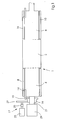
- Fig. 1 shows a simplified schematic view of a printing cylinder 1 having a central print image area 2, a first end 4 and a second end 6.
- a first sleeve 8 is arranged around the circumference of the first end 4, and a second sleeve 10 is around the Circumference of the second end 6 arranged around.
- the first sleeve 8 and the second sleeve 10 are rotatably attached to the first end 4 and the second end 6, for example by flanges 14.
- the first sleeve 8 and the second sleeve 10 are both axially displaceable relative to the central printed image area 2.
- the gear 19 is held by a thread on the drive shaft 21 in such a way that it moves axially with respect to the cylinder 2 and the drive shaft 21 with a rotation between the gear 19 and drive shaft 21 when a fan-out register adjustment device 17 for the first sleeve 8 is actuated.
- the Gear 19 is at an outer portion with a gear 27 in engagement, which is connected by a coupling 25 with a servomotor 23 of the device 17.
- the clutch 25 is engaged or closed and the motor 23 rotates the gear 27 to move the gear 19 axially with respect to the shaft 21.
- This movement pulls or pushes the flange 14, and thereby the sleeve 8, axially with respect to the central print image section 2.
- the coupling 25 is then disengaged so that the gear 19 and the shaft 21 rotate together again due to friction, for example.
- a further coupling may be provided to selectively lock the gear 19 and shaft 21 together or rotatably couple with each other.
- An overall register servo motor 29 may preferably move the entire cylinder 2 axially and circumferentially in a conventional manner. When the overall register is adjusted, the clutch 25 is disengaged and the gear 27 is axially displaceable with respect to the gear 19.
- the second sleeve 10 may include a device similar to the fan-out register adjustment device 17.
- first sleeve 8 and the second sleeve 10 can be moved axially by flanges, as described in U.S. Patent Application No. 09 / 627,639.
- the first sleeve 8 and the second sleeve 10 are rotated by the flanges 14 or by other support means which also stabilize the first sleeve 8 and the second sleeve 10 with respect to the impression cylinder 2.
- the first sleeve 8 and the second sleeve 10 each include a plurality of columns or channels 16 for inserting plates to allow pre-imaged plates to be mounted.
- the first sleeve 8 and the second sleeve 10 could also be directly laser-writable or coated with a laser-writable material.
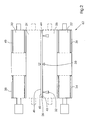
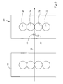
- Fig. 2 and Fig. 3 show a printing unit 60 of an offset printing machine, which has a first printing unit 58 in the same way.
- the printing unit 60 includes a first Printing cylinder 20 and a second pressure cylinder 22, which are each similar to the pressure cylinder 1 described in Fig. 1 are formed.
- a print image is transferred from the first impression cylinder 20 to a first blanket cylinder 24 to print on a first surface 41 of a web 28.
- Another print image is transferred from the second impression cylinder 22 to a second blanket cylinder 26 to print on a second surface 42 of the web 28.
- a plurality of first sensors 30 monitor the axial and circumferential registers for the web 28 by scanning marks on the web 28.
- a plurality of second sensors 32 scan additional marks indicative of the fan-out of the web 28 at the edge regions 43 and 44 enable the railway.
- the data obtained by the first sensors 30 and the second sensors 32 are used to axially move a first sleeve 34, a second sleeve 36, a third sleeve 38, and a fourth sleeve 40 for adjusting the pressure area to match the fanout of the Web 28 caused to minimize printing errors.
- the sensors 32 provide information regarding the fan-out caused by the first printing unit 58.
- the sleeves 38, 40, and 34, 36 may be moved outward by respective fan-out register setting devices with respect to the central print image areas to augment the fan-out minimize. For example, if the fan-out marks have shifted by 1 mm, the sleeves can be moved 0.5 mm outwards.
- the sensors 32 may provide automatic feedback to a controller that controls the fan-out register setting devices 17.
Landscapes
- Engineering & Computer Science (AREA)
- Mechanical Engineering (AREA)
- Inking, Control Or Cleaning Of Printing Machines (AREA)
- Folding Of Thin Sheet-Like Materials, Special Discharging Devices, And Others (AREA)
- Photosensitive Polymer And Photoresist Processing (AREA)
Applications Claiming Priority (2)
| Application Number | Priority Date | Filing Date | Title |
|---|---|---|---|
| US675494 | 2000-09-29 | ||
| US09/675,494 US6553908B1 (en) | 2000-09-29 | 2000-09-29 | Web fanout control system |
Publications (2)
| Publication Number | Publication Date |
|---|---|
| EP1193059A1 EP1193059A1 (de) | 2002-04-03 |
| EP1193059B1 true EP1193059B1 (de) | 2006-06-14 |
Family
ID=24710742
Family Applications (1)
| Application Number | Title | Priority Date | Filing Date |
|---|---|---|---|
| EP01121641A Expired - Lifetime EP1193059B1 (de) | 2000-09-29 | 2001-09-13 | Vorrichtung zur Regulierung des Breiterdruckens (Fan-Out) einer Bahn |
Country Status (5)
| Country | Link |
|---|---|
| US (1) | US6553908B1 (enExample) |
| EP (1) | EP1193059B1 (enExample) |
| JP (1) | JP2002160346A (enExample) |
| AT (1) | ATE329758T1 (enExample) |
| DE (2) | DE50110129D1 (enExample) |
Families Citing this family (16)
| Publication number | Priority date | Publication date | Assignee | Title |
|---|---|---|---|---|
| US6868783B2 (en) | 2001-09-07 | 2005-03-22 | Goss International Americas, Inc. | Printing press with multiple-image-carrying cylinder |
| US6851362B2 (en) * | 2002-03-22 | 2005-02-08 | Goss International Americas, Inc. | Printing cylinder with fanout compensation |
| DE10225199B4 (de) * | 2002-06-06 | 2004-05-06 | Maschinenfabrik Wifag | Fluidbeaufschlagter FanOut-Kompensator |
| DE10236865A1 (de) * | 2002-08-12 | 2004-02-26 | Koenig & Bauer Ag | Zylinder in einer Druckeinheit mit mindestens einem Kanal mit mindestens einer Haltevorrichtung |
| US6796233B2 (en) * | 2002-11-20 | 2004-09-28 | Heidelberger Druckmaschinen Ag | Plate cylinder with splined shell |
| DE10352619B4 (de) * | 2003-07-11 | 2012-09-27 | Koenig & Bauer Aktiengesellschaft | Verfahren und Vorrichtung zur Beeinflussung des Fan-Out-Effektes |
| DE10340569A1 (de) * | 2003-09-01 | 2005-04-07 | Koenig & Bauer Ag | Verfahren zur Reduktion von Passerfehlern auf einer in einer bahnverarbeitenden Vorrichtung und ein Druckwerk |
| WO2006104828A2 (en) * | 2005-03-30 | 2006-10-05 | Goss International Americas, Inc. | Cantilevered blanket cylinder lifting mechanism |
| EP1863641B1 (en) * | 2005-03-30 | 2015-10-14 | Goss International Americas, Inc. | Print unit having blanket cylinder throw-off bearer surfaces |
| EP1863639B1 (en) * | 2005-03-30 | 2012-05-02 | Goss International Americas, Inc. | Web offset printing press with autoplating |
| CN101111379B (zh) | 2005-03-30 | 2011-12-07 | 高斯国际美洲公司 | 带有枢接折页器的轮转胶版印刷机 |
| EP1868812A4 (en) * | 2005-04-11 | 2012-01-04 | Goss Int Americas Inc | PRINTING UNIT WITH AUTOPLATING OF ENHANCED ONE-MOTOR DRIVE |
| US8733249B2 (en) * | 2007-02-20 | 2014-05-27 | Goss International Americas, Inc. | Real-time print product status |
| US20110155006A1 (en) * | 2009-12-31 | 2011-06-30 | Bryce Corporation | Interlocking printing sleeves |
| DE202016102779U1 (de) * | 2016-05-25 | 2017-08-28 | Bobst Bielefeld Gmbh | Vorrichtung zur Betätigung einer hydraulischen Trägerstange einer Rotationsdruckmaschine |
| JP6934707B2 (ja) * | 2016-07-13 | 2021-09-15 | グローリー株式会社 | 有価証券の文字/番号検査装置及び文字/番号検査方法 |
Family Cites Families (8)
| Publication number | Priority date | Publication date | Assignee | Title |
|---|---|---|---|---|
| JPS5931467B2 (ja) | 1977-04-27 | 1984-08-02 | 株式会社東京機械製作所 | 輪転印刷機における版胴装置 |
| GB8729197D0 (en) | 1987-12-15 | 1988-01-27 | Ciba Geigy Ag | Preparation of polymeric colour couplers |
| JP2602488B2 (ja) * | 1989-05-30 | 1997-04-23 | 株式会社 東京機械製作所 | 両面多色印刷機 |
| JP2726716B2 (ja) | 1989-10-26 | 1998-03-11 | 三菱重工業株式会社 | 輪転印刷機の分割版胴 |
| JP2566897B2 (ja) | 1992-07-29 | 1996-12-25 | 株式会社東京機械製作所 | 多色刷平版印刷機 |
| JP3140245B2 (ja) | 1993-03-19 | 2001-03-05 | オリンパス光学工業株式会社 | レンズ鏡筒 |
| US5365847A (en) | 1993-09-22 | 1994-11-22 | Rockwell International Corporation | Control system for a printing press |
| WO1998018626A1 (de) * | 1996-10-25 | 1998-05-07 | Koenig & Bauer Aktiengesellschaft | Anordnung zur korrektur des fan-out-effektes an rollenrotationsdruckmaschinen |
-
2000
- 2000-09-29 US US09/675,494 patent/US6553908B1/en not_active Expired - Fee Related
-
2001
- 2001-09-13 DE DE50110129T patent/DE50110129D1/de not_active Expired - Lifetime
- 2001-09-13 DE DE10145016A patent/DE10145016A1/de not_active Withdrawn
- 2001-09-13 AT AT01121641T patent/ATE329758T1/de not_active IP Right Cessation
- 2001-09-13 EP EP01121641A patent/EP1193059B1/de not_active Expired - Lifetime
- 2001-09-27 JP JP2001297569A patent/JP2002160346A/ja active Pending
Also Published As
| Publication number | Publication date |
|---|---|
| DE50110129D1 (de) | 2006-07-27 |
| EP1193059A1 (de) | 2002-04-03 |
| DE10145016A1 (de) | 2002-07-25 |
| US6553908B1 (en) | 2003-04-29 |
| ATE329758T1 (de) | 2006-07-15 |
| JP2002160346A (ja) | 2002-06-04 |
Similar Documents
| Publication | Publication Date | Title |
|---|---|---|
| DE69809000T2 (de) | Druckmaschine mit auf einem Schlitten montierten austauschbaren Plattenzylindern | |
| EP1666252B1 (de) | Vorrichtung und Verfahren zur Einstellung des Druckbildes in einer Flexodruckmaschine | |
| EP0136972B1 (de) | Kombinierte Bogenrotationsdruckmaschine für Wertpapiere, insbesondere Banknoten | |
| DE3136703C1 (de) | Einrichtungen an Druckmaschinen mit Registerverstelleinrichtungen | |
| EP0422412B1 (de) | Vorrichtung und Verfahren zur Registerverstellung an einer Druckmaschine mit mehreren Druckwerken | |
| DE4327211B4 (de) | Vorrichtung zum Voreinstellen des Schnittregisters in dem Falzapparat einer Rollendruckmaschine | |
| EP1193059A1 (de) | Vorrichtung zur Regulierung des Breiterdruckens (Fan-Out) einer Bahn | |
| EP2014470B1 (de) | Verfahren zur automatischen Regelung des Registers zwischen Abdrucken in einer Mehrfarben-Rotationsdruckmaschine | |
| EP1620265A2 (de) | Systeme zur inspektion eines druckbildes | |
| EP0806294B1 (de) | Verfahren und Vorrichtung zum Einstellen des Umfangsregisters in einer Rollenrotationsdruckmaschine mit einem eine hülsenförmige Druckplatte tragenden Plattenzylinder | |
| EP0782919A1 (de) | Druckwerk für eine Rollenrotationsdruckmaschine | |
| EP1291175B1 (de) | Druckzylinder zur Aufnahme mehrerer Bilder | |
| EP1572457B1 (de) | Vorregistereinstellung | |
| DE29501373U1 (de) | Vorrichtung zur Korrektur des Fan-Out-Effekts an Rollenrotationsdruckmaschinen | |
| EP1843898B1 (de) | Registerverfahren | |
| DE29718968U1 (de) | Anordnung zur Korrektur des Fan-Out-Effektes an Rollenrotationsdruckmaschinen | |
| EP1050404B1 (de) | Offsetdruckmaschine zum Bedrucken von zwei Bahnen | |
| DE3112775C2 (de) | Rotationsdruckmaschine in Reihenbauweise | |
| DE4218761A1 (de) | Verfahren zum Voreinstellen von Registereinstellvorrichtungen an Rotationsdruckmaschinen | |
| WO2000034042A1 (de) | Verfahren zur regelung eines registers | |
| EP1457334A1 (de) | Vorrichtung und Verfahren zur Registersteuerung in einer Druckmaschine | |
| DE4410132C2 (de) | Flexodruckmaschine, insbesondere für Mehrfarbendruck | |
| EP0995596A1 (de) | Vorrichtung und Verfahren zur Durchführung eines fleigenden Plattenwechsels | |
| DE10232109A1 (de) | Offsetdruckwerk und Offsetdruckverfahren | |
| EP1773702A1 (de) | Verfahrenen und vorrichtungen zur positionierung von bahnbearbeitungswerkzeugen bzw. zur voreinstellung einer schnittbreite |
Legal Events
| Date | Code | Title | Description |
|---|---|---|---|
| PUAI | Public reference made under article 153(3) epc to a published international application that has entered the european phase |
Free format text: ORIGINAL CODE: 0009012 |
|
| AK | Designated contracting states |
Kind code of ref document: A1 Designated state(s): AT BE CH CY DE DK ES FI FR GB GR IE IT LI LU MC NL PT SE TR |
|
| AX | Request for extension of the european patent |
Free format text: AL;LT;LV;MK;RO;SI |
|
| 17P | Request for examination filed |
Effective date: 20020128 |
|
| AKX | Designation fees paid |
Free format text: AT BE CH CY DE DK ES FI FR GB GR IE IT LI LU MC NL PT SE TR |
|
| RAP1 | Party data changed (applicant data changed or rights of an application transferred) |
Owner name: GOSS INTERNATIONAL AMERICAS, INC. |
|
| GRAP | Despatch of communication of intention to grant a patent |
Free format text: ORIGINAL CODE: EPIDOSNIGR1 |
|
| GRAS | Grant fee paid |
Free format text: ORIGINAL CODE: EPIDOSNIGR3 |
|
| GRAA | (expected) grant |
Free format text: ORIGINAL CODE: 0009210 |
|
| AK | Designated contracting states |
Kind code of ref document: B1 Designated state(s): AT BE CH CY DE DK ES FI FR GB GR IE IT LI LU MC NL PT SE TR |
|
| PG25 | Lapsed in a contracting state [announced via postgrant information from national office to epo] |
Ref country code: NL Free format text: LAPSE BECAUSE OF FAILURE TO SUBMIT A TRANSLATION OF THE DESCRIPTION OR TO PAY THE FEE WITHIN THE PRESCRIBED TIME-LIMIT Effective date: 20060614 Ref country code: GB Free format text: LAPSE BECAUSE OF FAILURE TO SUBMIT A TRANSLATION OF THE DESCRIPTION OR TO PAY THE FEE WITHIN THE PRESCRIBED TIME-LIMIT Effective date: 20060614 Ref country code: IE Free format text: LAPSE BECAUSE OF FAILURE TO SUBMIT A TRANSLATION OF THE DESCRIPTION OR TO PAY THE FEE WITHIN THE PRESCRIBED TIME-LIMIT Effective date: 20060614 Ref country code: FI Free format text: LAPSE BECAUSE OF FAILURE TO SUBMIT A TRANSLATION OF THE DESCRIPTION OR TO PAY THE FEE WITHIN THE PRESCRIBED TIME-LIMIT Effective date: 20060614 Ref country code: IT Free format text: LAPSE BECAUSE OF FAILURE TO SUBMIT A TRANSLATION OF THE DESCRIPTION OR TO PAY THE FEE WITHIN THE PRESCRIBED TIME-LIMIT;WARNING: LAPSES OF ITALIAN PATENTS WITH EFFECTIVE DATE BEFORE 2007 MAY HAVE OCCURRED AT ANY TIME BEFORE 2007. THE CORRECT EFFECTIVE DATE MAY BE DIFFERENT FROM THE ONE RECORDED. Effective date: 20060614 |
|
| REG | Reference to a national code |
Ref country code: GB Ref legal event code: FG4D Free format text: NOT ENGLISH |
|
| REG | Reference to a national code |
Ref country code: CH Ref legal event code: EP |
|
| REG | Reference to a national code |
Ref country code: CH Ref legal event code: NV Representative=s name: KIRKER & CIE SA |
|
| REG | Reference to a national code |
Ref country code: IE Ref legal event code: FG4D Free format text: LANGUAGE OF EP DOCUMENT: GERMAN |
|
| REF | Corresponds to: |
Ref document number: 50110129 Country of ref document: DE Date of ref document: 20060727 Kind code of ref document: P |
|
| PG25 | Lapsed in a contracting state [announced via postgrant information from national office to epo] |
Ref country code: DK Free format text: LAPSE BECAUSE OF FAILURE TO SUBMIT A TRANSLATION OF THE DESCRIPTION OR TO PAY THE FEE WITHIN THE PRESCRIBED TIME-LIMIT Effective date: 20060914 Ref country code: SE Free format text: LAPSE BECAUSE OF FAILURE TO SUBMIT A TRANSLATION OF THE DESCRIPTION OR TO PAY THE FEE WITHIN THE PRESCRIBED TIME-LIMIT Effective date: 20060914 |
|
| PGFP | Annual fee paid to national office [announced via postgrant information from national office to epo] |
Ref country code: FR Payment date: 20060918 Year of fee payment: 6 |
|
| PG25 | Lapsed in a contracting state [announced via postgrant information from national office to epo] |
Ref country code: ES Free format text: LAPSE BECAUSE OF FAILURE TO SUBMIT A TRANSLATION OF THE DESCRIPTION OR TO PAY THE FEE WITHIN THE PRESCRIBED TIME-LIMIT Effective date: 20060925 |
|
| PGFP | Annual fee paid to national office [announced via postgrant information from national office to epo] |
Ref country code: GB Payment date: 20060925 Year of fee payment: 6 |
|
| PG25 | Lapsed in a contracting state [announced via postgrant information from national office to epo] |
Ref country code: MC Free format text: LAPSE BECAUSE OF NON-PAYMENT OF DUE FEES Effective date: 20060930 Ref country code: BE Free format text: LAPSE BECAUSE OF NON-PAYMENT OF DUE FEES Effective date: 20060930 |
|
| PG25 | Lapsed in a contracting state [announced via postgrant information from national office to epo] |
Ref country code: PT Free format text: LAPSE BECAUSE OF FAILURE TO SUBMIT A TRANSLATION OF THE DESCRIPTION OR TO PAY THE FEE WITHIN THE PRESCRIBED TIME-LIMIT Effective date: 20061114 |
|
| NLV1 | Nl: lapsed or annulled due to failure to fulfill the requirements of art. 29p and 29m of the patents act | ||
| GBV | Gb: ep patent (uk) treated as always having been void in accordance with gb section 77(7)/1977 [no translation filed] |
Effective date: 20060614 |
|
| REG | Reference to a national code |
Ref country code: IE Ref legal event code: FD4D |
|
| PLBE | No opposition filed within time limit |
Free format text: ORIGINAL CODE: 0009261 |
|
| STAA | Information on the status of an ep patent application or granted ep patent |
Free format text: STATUS: NO OPPOSITION FILED WITHIN TIME LIMIT |
|
| EN | Fr: translation not filed | ||
| 26N | No opposition filed |
Effective date: 20070315 |
|
| PG25 | Lapsed in a contracting state [announced via postgrant information from national office to epo] |
Ref country code: AT Free format text: LAPSE BECAUSE OF NON-PAYMENT OF DUE FEES Effective date: 20060913 |
|
| BERE | Be: lapsed |
Owner name: GOSS INTERNATIONAL AMERICAS, INC. Effective date: 20060930 |
|
| PG25 | Lapsed in a contracting state [announced via postgrant information from national office to epo] |
Ref country code: GR Free format text: LAPSE BECAUSE OF FAILURE TO SUBMIT A TRANSLATION OF THE DESCRIPTION OR TO PAY THE FEE WITHIN THE PRESCRIBED TIME-LIMIT Effective date: 20060915 Ref country code: FR Free format text: LAPSE BECAUSE OF FAILURE TO SUBMIT A TRANSLATION OF THE DESCRIPTION OR TO PAY THE FEE WITHIN THE PRESCRIBED TIME-LIMIT Effective date: 20070309 |
|
| PG25 | Lapsed in a contracting state [announced via postgrant information from national office to epo] |
Ref country code: TR Free format text: LAPSE BECAUSE OF FAILURE TO SUBMIT A TRANSLATION OF THE DESCRIPTION OR TO PAY THE FEE WITHIN THE PRESCRIBED TIME-LIMIT Effective date: 20060614 Ref country code: LU Free format text: LAPSE BECAUSE OF NON-PAYMENT OF DUE FEES Effective date: 20060913 |
|
| PG25 | Lapsed in a contracting state [announced via postgrant information from national office to epo] |
Ref country code: CY Free format text: LAPSE BECAUSE OF FAILURE TO SUBMIT A TRANSLATION OF THE DESCRIPTION OR TO PAY THE FEE WITHIN THE PRESCRIBED TIME-LIMIT Effective date: 20060614 |
|
| PGFP | Annual fee paid to national office [announced via postgrant information from national office to epo] |
Ref country code: CH Payment date: 20100930 Year of fee payment: 10 |
|
| PGFP | Annual fee paid to national office [announced via postgrant information from national office to epo] |
Ref country code: DE Payment date: 20100929 Year of fee payment: 10 |
|
| REG | Reference to a national code |
Ref country code: CH Ref legal event code: PL |
|
| PG25 | Lapsed in a contracting state [announced via postgrant information from national office to epo] |
Ref country code: LI Free format text: LAPSE BECAUSE OF NON-PAYMENT OF DUE FEES Effective date: 20110930 Ref country code: CH Free format text: LAPSE BECAUSE OF NON-PAYMENT OF DUE FEES Effective date: 20110930 |
|
| REG | Reference to a national code |
Ref country code: DE Ref legal event code: R119 Ref document number: 50110129 Country of ref document: DE Effective date: 20130403 |
|
| PG25 | Lapsed in a contracting state [announced via postgrant information from national office to epo] |
Ref country code: DE Free format text: LAPSE BECAUSE OF NON-PAYMENT OF DUE FEES Effective date: 20130403 |