EP1190782A2 - Vorrichtung zur Dämpfung von Schwingungen und zur Reduzierung axialer Durchbiegungen der Tragwellen von fliegend angeordneten Walzpaaren - Google Patents
Vorrichtung zur Dämpfung von Schwingungen und zur Reduzierung axialer Durchbiegungen der Tragwellen von fliegend angeordneten Walzpaaren Download PDFInfo
- Publication number
- EP1190782A2 EP1190782A2 EP01119494A EP01119494A EP1190782A2 EP 1190782 A2 EP1190782 A2 EP 1190782A2 EP 01119494 A EP01119494 A EP 01119494A EP 01119494 A EP01119494 A EP 01119494A EP 1190782 A2 EP1190782 A2 EP 1190782A2
- Authority
- EP
- European Patent Office
- Prior art keywords
- support shafts
- pressure
- damping vibrations
- bearings
- reducing axial
- Prior art date
- Legal status (The legal status is an assumption and is not a legal conclusion. Google has not performed a legal analysis and makes no representation as to the accuracy of the status listed.)
- Granted
Links
Images

Classifications
-
- B—PERFORMING OPERATIONS; TRANSPORTING
- B21—MECHANICAL METAL-WORKING WITHOUT ESSENTIALLY REMOVING MATERIAL; PUNCHING METAL
- B21B—ROLLING OF METAL
- B21B29/00—Counter-pressure devices acting on rolls to inhibit deflection of same under load, e.g. backing rolls ; Roll bending devices, e.g. hydraulic actuators acting on roll shaft ends
-
- B—PERFORMING OPERATIONS; TRANSPORTING
- B21—MECHANICAL METAL-WORKING WITHOUT ESSENTIALLY REMOVING MATERIAL; PUNCHING METAL
- B21B—ROLLING OF METAL
- B21B31/00—Rolling stand structures; Mounting, adjusting, or interchanging rolls, roll mountings, or stand frames
- B21B31/07—Adaptation of roll neck bearings
-
- B—PERFORMING OPERATIONS; TRANSPORTING
- B21—MECHANICAL METAL-WORKING WITHOUT ESSENTIALLY REMOVING MATERIAL; PUNCHING METAL
- B21B—ROLLING OF METAL
- B21B13/00—Metal-rolling stands, i.e. an assembly composed of a stand frame, rolls, and accessories
- B21B13/005—Cantilevered roll stands
-
- B—PERFORMING OPERATIONS; TRANSPORTING
- B21—MECHANICAL METAL-WORKING WITHOUT ESSENTIALLY REMOVING MATERIAL; PUNCHING METAL
- B21B—ROLLING OF METAL
- B21B2203/00—Auxiliary arrangements, devices or methods in combination with rolling mills or rolling methods
- B21B2203/44—Vibration dampers
-
- B—PERFORMING OPERATIONS; TRANSPORTING
- B21—MECHANICAL METAL-WORKING WITHOUT ESSENTIALLY REMOVING MATERIAL; PUNCHING METAL
- B21B—ROLLING OF METAL
- B21B31/00—Rolling stand structures; Mounting, adjusting, or interchanging rolls, roll mountings, or stand frames
- B21B31/07—Adaptation of roll neck bearings
- B21B31/074—Oil film bearings, e.g. "Morgoil" bearings
-
- B—PERFORMING OPERATIONS; TRANSPORTING
- B21—MECHANICAL METAL-WORKING WITHOUT ESSENTIALLY REMOVING MATERIAL; PUNCHING METAL
- B21B—ROLLING OF METAL
- B21B31/00—Rolling stand structures; Mounting, adjusting, or interchanging rolls, roll mountings, or stand frames
- B21B31/16—Adjusting or positioning rolls
- B21B31/20—Adjusting or positioning rolls by moving rolls perpendicularly to roll axis
- B21B31/22—Adjusting or positioning rolls by moving rolls perpendicularly to roll axis mechanically, e.g. by thrust blocks, inserts for removal
- B21B31/26—Adjusting eccentrically-mounted roll bearings
-
- B—PERFORMING OPERATIONS; TRANSPORTING
- B21—MECHANICAL METAL-WORKING WITHOUT ESSENTIALLY REMOVING MATERIAL; PUNCHING METAL
- B21B—ROLLING OF METAL
- B21B37/00—Control devices or methods specially adapted for metal-rolling mills or the work produced thereby
- B21B37/007—Control for preventing or reducing vibration, chatter or chatter marks
Definitions
- the invention relates to a device for damping vibrations and to reduce axial deflections of the support shafts from overhung ones Roller pairs in the finishing stand arrangements of, at high speeds operated wire rolling mills, where the supporting shafts each store on both sides in eccentrically rotatable bearing housings and have drive pinions between the bearings.
- the invention has for its object the bending of the roller shafts directly to influence and thus also the vibrations caused by these counteract.
- This pressure sleeve, the z. B. can be similar to a plain bearing, and where the play between the bushing and the support shaft is independent of the two Storage and is definable and adjustable regardless of their oil supply, allows to counteract the deflection of the supporting shafts and thus spring movements of the rollers of the pair of rollers, which the uniformity of the cross section of the nip formed by this and thus that of the cross section of the Impact rolling gap passing through, limit and thus also eliminate the causes of vibrations of the support rollers.
- two bearing housings LG1 and LG2 are parallel to one another lying around its longitudinal center axis with both ends LGE1 and LGE2 rotatably supported in the WG rolling mill.
- the two ends LGE1 and LGE2 are eccentric to the respective longitudinal center axis of the bearing housings LG1 and LG2 the main bearing HL1 or HL2 and the secondary bearing NL1 or NL2 of the pair of supporting shafts TW1, TW2 arranged.
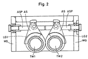
- the two bearing housings LG1 and LG2 have (see FIG. 2) radial support lugs AS, which are arranged in the rolling stand WG ASP lead screws are articulated.
- each a pressure bushing DB1 or DB2 set up On both support shafts TW1 and TW2 between the respective main bearings HL1, HL2 and auxiliary bearings NL1, NL2 with the roll stand WG each a pressure bushing DB1 or DB2 set up, which encompass their scope.
- Each of these pressure cans DB1 or DB2 is not connected to a separate pressure line DL1 or DL2 connected pressure control device, with the help of the pressure rooms DR1 or DR2 of the pressure bushes DB1 or DB2 are pressurized with the pressure medium become.
- the curve line labeled BLN indicates the bending line that the support shaft, here takes TB2 during rolling operation without inserting the pressure sleeve DB2 and the curve line labeled BLD, the one with the insertion of the pressure sleeve DB2 achievable, substantially flat bending line of the support shaft TB2.
Landscapes
- Engineering & Computer Science (AREA)
- Mechanical Engineering (AREA)
- Support Of The Bearing (AREA)
- Rolls And Other Rotary Bodies (AREA)
- Rolling Contact Bearings (AREA)
- Reduction Rolling/Reduction Stand/Operation Of Reduction Machine (AREA)
- Metal Rolling (AREA)
- Paper (AREA)
- Vibration Prevention Devices (AREA)
- Rollers For Roller Conveyors For Transfer (AREA)
Abstract
Description
- Figur 1
- die teilweise geschnittene Draufsicht auf die Vorrichtung und
- Figur 2
- einen Radialschnitt durch Figur 1.
- LG1
- Lagergehäuse
- LG2
- Lagergehäuse
- LGE1
- Lagergehäuseende
- LGE2
- Lagergehäuseende
- WG
- Walzgerüst
- HL1
- Hauptlager
- HL2
- Hauptlager
- NL1
- Nebenlager
- NL2
- Nebenlager
- TW1
- Tragwelle
- TW2
- Tragwelle
- AS
- Tragansätze
- ASP
- Anstellspindel
- WZ1
- Walzenzapfen
- WZ2
- Walzenzapfen
- W1
- Walze
- W2
- Walze
- AR1
- Antriebsritzel
- AR2
- Antriebsritzel
- DB1
- Druckbüchse
- DB2
- Druckbüchse
- DL1
- Druckleitung
- DL2
- Druckleitung
- DR1
- Druckraum
- DR2
- Druckraum
- BLN
- Kurve
- BLD
- Kruve
Claims (2)
- Vorrichtung zur Dämpfung von Schwingungen und zur Reduzierung axsialer Durchbiegungen der Tragwellen (TW) von fliegend angeordneten Walzenpaaren (W) in den Fertiggerüstanordnungen von, mit hoher Geschwindigkeit betriebenen Drahtwalzstraßen, bei der die Tragwellen (TW) jeweils zweiseitig in exentrisch gegeneinander verstellbaren Lagergehäusen (LG) lagern und zwischen den Lagern (HL; NL) Antriebsritzel (AR) tragen,
dadurch gekennzeichnet, dass auf jeder der Tragwellen (TW1; TW2) zwischen deren beiden Lagern (HL1; HL2) eine, fest mit dem exentrisch verstellbaren Lagergehäuse (LG1; LG2) verbundene, mit einer druck- und volumeneinstellbaren Druckflüssigkeit beaufschlagbare an sich bekannte Druckbüchse (DB1; DB2) angeordnet ist. - Vorrichtung nach Anspruch 1,
dadurch gekennzeichnet, dass die Druckbüchse (DB1; DB2) in der Längsachsrichtung der Tragwelle (TB1; TB2) verschieb- und und/oder gegenüber dieser schwenkbar ausgebildet ist.
Applications Claiming Priority (2)
| Application Number | Priority Date | Filing Date | Title |
|---|---|---|---|
| DE10046428 | 2000-09-20 | ||
| DE10046428A DE10046428A1 (de) | 2000-09-20 | 2000-09-20 | Vorrichtung zur Dämpfung von Schwingungen und zur Reduzierung achsialer Durchbiegungen der Tragwellen von fliegend angeordneten Walzenpaaren |
Publications (3)
| Publication Number | Publication Date |
|---|---|
| EP1190782A2 true EP1190782A2 (de) | 2002-03-27 |
| EP1190782A3 EP1190782A3 (de) | 2004-03-17 |
| EP1190782B1 EP1190782B1 (de) | 2005-10-26 |
Family
ID=7656851
Family Applications (1)
| Application Number | Title | Priority Date | Filing Date |
|---|---|---|---|
| EP01119494A Expired - Lifetime EP1190782B1 (de) | 2000-09-20 | 2001-08-14 | Vorrichtung zur Dämpfung von Schwingungen und zur Reduzierung axialer Durchbiegungen der Tragwellen von fliegend angeordneten Walzpaaren |
Country Status (4)
| Country | Link |
|---|---|
| US (1) | US6561003B2 (de) |
| EP (1) | EP1190782B1 (de) |
| AT (1) | ATE307688T1 (de) |
| DE (2) | DE10046428A1 (de) |
Families Citing this family (7)
| Publication number | Priority date | Publication date | Assignee | Title |
|---|---|---|---|---|
| US6959579B2 (en) * | 2003-05-08 | 2005-11-01 | Morgan Construction Company | Triple bearing arrangement for cantilevered roll shafts |
| CN1301809C (zh) * | 2004-04-21 | 2007-02-28 | 摩根建设公司 | 悬臂辊轴的三轴承结构 |
| US9421602B2 (en) | 2013-12-18 | 2016-08-23 | United Technologies Corporation | Machine for deep rolling tool positioning |
| US9566638B2 (en) * | 2013-12-18 | 2017-02-14 | United Technologies Corporation | Deep rolling tool with force adjustment |
| US9573175B2 (en) | 2013-12-18 | 2017-02-21 | United Technologies Corporation | Deep rolling tool for blade fatigue life enhancement |
| US9573184B2 (en) | 2013-12-18 | 2017-02-21 | United Technologies Corporation | Deep rolling tool for processing blade root |
| US9937641B1 (en) * | 2015-12-31 | 2018-04-10 | Bryce Corporation | Quick release sleeve chill roll |
Family Cites Families (6)
| Publication number | Priority date | Publication date | Assignee | Title |
|---|---|---|---|---|
| DE1255449B (de) * | 1958-07-26 | 1967-11-30 | Robert Ohrnberger Dipl Ing | Vorrichtung zur Lagerung und Klemmung der Arbeitsspindeln von Werkzeugmaschinen, insbesondere Bohr- und Fraeswerken |
| US4036030A (en) * | 1973-09-18 | 1977-07-19 | Hermann Ernst Robert Papst | Assembly for the damping of flexural and torsional vibration in the shafts of machines |
| DE3509613A1 (de) * | 1985-03-16 | 1986-09-18 | Kocks Technik Gmbh & Co, 4010 Hilden | Lagerung fuer eine umlaufende welle |
| JPS6384707A (ja) * | 1986-09-26 | 1988-04-15 | Kobe Steel Ltd | 圧延機の軸受装置 |
| US4772137A (en) | 1987-03-30 | 1988-09-20 | Morgan Construction Company | Oil film bearing and bushing |
| DE19628956A1 (de) * | 1996-07-18 | 1998-01-22 | Schloemann Siemag Ag | Exzenter-Lagerhülse für Walzentragwellen |
-
2000
- 2000-09-20 DE DE10046428A patent/DE10046428A1/de not_active Withdrawn
-
2001
- 2001-08-14 EP EP01119494A patent/EP1190782B1/de not_active Expired - Lifetime
- 2001-08-14 AT AT01119494T patent/ATE307688T1/de not_active IP Right Cessation
- 2001-08-14 DE DE50107805T patent/DE50107805D1/de not_active Expired - Fee Related
- 2001-09-19 US US09/955,914 patent/US6561003B2/en not_active Expired - Fee Related
Also Published As
| Publication number | Publication date |
|---|---|
| EP1190782B1 (de) | 2005-10-26 |
| DE50107805D1 (de) | 2005-12-01 |
| EP1190782A3 (de) | 2004-03-17 |
| DE10046428A1 (de) | 2002-03-28 |
| US20020033037A1 (en) | 2002-03-21 |
| US6561003B2 (en) | 2003-05-13 |
| ATE307688T1 (de) | 2005-11-15 |
Similar Documents
| Publication | Publication Date | Title |
|---|---|---|
| DE69502550T2 (de) | Profilanpassung für Vielwalzengerüste | |
| EP1190782B1 (de) | Vorrichtung zur Dämpfung von Schwingungen und zur Reduzierung axialer Durchbiegungen der Tragwellen von fliegend angeordneten Walzpaaren | |
| DE102009037274A1 (de) | Walze und ein Walzgerüst zum Walzen von Walzgut | |
| EP2032866B1 (de) | Lager für walzwerkswalzen | |
| DE19807601C1 (de) | Walzwerk mit Arbeitswalzen und mehrteiligen Stützwalzen | |
| EP0154249B1 (de) | Walzgerüst mit auf ein Walzentragwellenpaar einseitig (fliegend) aufgesestzten Walzringen | |
| EP0768125B1 (de) | Führungsvorrichtung für Vier- oder Mehrwalzengerüste | |
| DE10393228C5 (de) | Pressvorrichtung | |
| EP1256399B1 (de) | Querwalzmaschine | |
| EP0734794B1 (de) | Walzgerüst mit Stütz- und Arbeitswalzen zum Walzen von Blechen und Bändern | |
| DE3736683C3 (de) | Mehrrollen-Walzgerüst | |
| EP1506839A1 (de) | Werkzeug zur Feinstbearbeitung | |
| DE3514464C2 (de) | ||
| EP0829314A1 (de) | Lagerung für biegesteife Mantelwalzen auf einer Tragachse oder Tragwelle | |
| EP1256398B1 (de) | Querwalzmaschine | |
| WO2024028156A1 (de) | Walzwerksanordnung zur übertragung hoher drehmomente | |
| AT403034B (de) | Walze für maschinen zur führung von bahnenförmigem flächigen material | |
| DE1936769A1 (de) | Vorrichtung zur Balligkeitssteuerung der Arbeitswalzen in einem Duo-Metallwalzwerk | |
| DE3107858A1 (de) | Walzgeruest fuer stangen und walzdraht | |
| DE3407207A1 (de) | Walzgeruest mit auf ein walzentragwellenpaar einseitig (fliegend) aufgesetzten walzringen | |
| DE8425635U1 (de) | Flanschen-Stauchgerüst für Universal-Profilwalzstrassen | |
| DE1427943A1 (de) | Stauchwalzenpaar mit frei zugaenglichem Walzspalt fuer Zwei-Walzenstuehle | |
| EP0042124A1 (de) | Walze für ein Doppel-Duo-Reversier-Walzgerüst mit gegenläufigen Walzenpaaren | |
| DE4302819C2 (de) | Lagerausbildung für Walzwerkswalzen | |
| EP0824045A2 (de) | Exzenter-Lagerhülse für Walzentragwellen |
Legal Events
| Date | Code | Title | Description |
|---|---|---|---|
| PUAI | Public reference made under article 153(3) epc to a published international application that has entered the european phase |
Free format text: ORIGINAL CODE: 0009012 |
|
| 17P | Request for examination filed |
Effective date: 20010814 |
|
| AK | Designated contracting states |
Kind code of ref document: A2 Designated state(s): AT BE CH CY DE DK ES FI FR GB GR IE IT LI LU MC NL PT SE TR |
|
| AX | Request for extension of the european patent |
Free format text: AL;LT;LV;MK;RO;SI |
|
| PUAL | Search report despatched |
Free format text: ORIGINAL CODE: 0009013 |
|
| AK | Designated contracting states |
Kind code of ref document: A3 Designated state(s): AT BE CH CY DE DK ES FI FR GB GR IE IT LI LU MC NL PT SE TR |
|
| AX | Request for extension of the european patent |
Extension state: AL LT LV MK RO SI |
|
| AKX | Designation fees paid |
Designated state(s): AT BE CH CY DE DK ES FI FR GB GR IE IT LI LU MC NL PT SE TR |
|
| 17Q | First examination report despatched |
Effective date: 20041115 |
|
| GRAP | Despatch of communication of intention to grant a patent |
Free format text: ORIGINAL CODE: EPIDOSNIGR1 |
|
| GRAS | Grant fee paid |
Free format text: ORIGINAL CODE: EPIDOSNIGR3 |
|
| GRAL | Information related to payment of fee for publishing/printing deleted |
Free format text: ORIGINAL CODE: EPIDOSDIGR3 |
|
| GRAS | Grant fee paid |
Free format text: ORIGINAL CODE: EPIDOSNIGR3 |
|
| GRAA | (expected) grant |
Free format text: ORIGINAL CODE: 0009210 |
|
| AK | Designated contracting states |
Kind code of ref document: B1 Designated state(s): AT BE CH CY DE DK ES FI FR GB GR IE IT LI LU MC NL PT SE TR |
|
| PG25 | Lapsed in a contracting state [announced via postgrant information from national office to epo] |
Ref country code: FI Free format text: LAPSE BECAUSE OF FAILURE TO SUBMIT A TRANSLATION OF THE DESCRIPTION OR TO PAY THE FEE WITHIN THE PRESCRIBED TIME-LIMIT Effective date: 20051026 Ref country code: IE Free format text: LAPSE BECAUSE OF FAILURE TO SUBMIT A TRANSLATION OF THE DESCRIPTION OR TO PAY THE FEE WITHIN THE PRESCRIBED TIME-LIMIT Effective date: 20051026 Ref country code: NL Free format text: LAPSE BECAUSE OF FAILURE TO SUBMIT A TRANSLATION OF THE DESCRIPTION OR TO PAY THE FEE WITHIN THE PRESCRIBED TIME-LIMIT Effective date: 20051026 |
|
| REG | Reference to a national code |
Ref country code: GB Ref legal event code: FG4D Free format text: NOT ENGLISH |
|
| REG | Reference to a national code |
Ref country code: CH Ref legal event code: EP |
|
| REG | Reference to a national code |
Ref country code: IE Ref legal event code: FG4D Free format text: LANGUAGE OF EP DOCUMENT: GERMAN |
|
| REF | Corresponds to: |
Ref document number: 50107805 Country of ref document: DE Date of ref document: 20051201 Kind code of ref document: P |
|
| REG | Reference to a national code |
Ref country code: SE Ref legal event code: TRGR |
|
| PG25 | Lapsed in a contracting state [announced via postgrant information from national office to epo] |
Ref country code: DK Free format text: LAPSE BECAUSE OF FAILURE TO SUBMIT A TRANSLATION OF THE DESCRIPTION OR TO PAY THE FEE WITHIN THE PRESCRIBED TIME-LIMIT Effective date: 20060126 Ref country code: GR Free format text: LAPSE BECAUSE OF FAILURE TO SUBMIT A TRANSLATION OF THE DESCRIPTION OR TO PAY THE FEE WITHIN THE PRESCRIBED TIME-LIMIT Effective date: 20060126 |
|
| PG25 | Lapsed in a contracting state [announced via postgrant information from national office to epo] |
Ref country code: ES Free format text: LAPSE BECAUSE OF FAILURE TO SUBMIT A TRANSLATION OF THE DESCRIPTION OR TO PAY THE FEE WITHIN THE PRESCRIBED TIME-LIMIT Effective date: 20060206 |
|
| GBT | Gb: translation of ep patent filed (gb section 77(6)(a)/1977) |
Effective date: 20060215 |
|
| PG25 | Lapsed in a contracting state [announced via postgrant information from national office to epo] |
Ref country code: PT Free format text: LAPSE BECAUSE OF FAILURE TO SUBMIT A TRANSLATION OF THE DESCRIPTION OR TO PAY THE FEE WITHIN THE PRESCRIBED TIME-LIMIT Effective date: 20060327 |
|
| NLV1 | Nl: lapsed or annulled due to failure to fulfill the requirements of art. 29p and 29m of the patents act | ||
| REG | Reference to a national code |
Ref country code: IE Ref legal event code: FD4D |
|
| PGFP | Annual fee paid to national office [announced via postgrant information from national office to epo] |
Ref country code: AT Payment date: 20060816 Year of fee payment: 6 Ref country code: DE Payment date: 20060816 Year of fee payment: 6 |
|
| PGFP | Annual fee paid to national office [announced via postgrant information from national office to epo] |
Ref country code: GB Payment date: 20060824 Year of fee payment: 6 |
|
| PG25 | Lapsed in a contracting state [announced via postgrant information from national office to epo] |
Ref country code: LI Free format text: LAPSE BECAUSE OF NON-PAYMENT OF DUE FEES Effective date: 20060831 Ref country code: CH Free format text: LAPSE BECAUSE OF NON-PAYMENT OF DUE FEES Effective date: 20060831 Ref country code: MC Free format text: LAPSE BECAUSE OF NON-PAYMENT OF DUE FEES Effective date: 20060831 Ref country code: BE Free format text: LAPSE BECAUSE OF NON-PAYMENT OF DUE FEES Effective date: 20060831 |
|
| PGFP | Annual fee paid to national office [announced via postgrant information from national office to epo] |
Ref country code: IT Payment date: 20060831 Year of fee payment: 6 |
|
| PLBE | No opposition filed within time limit |
Free format text: ORIGINAL CODE: 0009261 |
|
| STAA | Information on the status of an ep patent application or granted ep patent |
Free format text: STATUS: NO OPPOSITION FILED WITHIN TIME LIMIT |
|
| 26N | No opposition filed |
Effective date: 20060727 |
|
| EN | Fr: translation not filed | ||
| PG25 | Lapsed in a contracting state [announced via postgrant information from national office to epo] |
Ref country code: FR Free format text: LAPSE BECAUSE OF FAILURE TO SUBMIT A TRANSLATION OF THE DESCRIPTION OR TO PAY THE FEE WITHIN THE PRESCRIBED TIME-LIMIT Effective date: 20061215 |
|
| REG | Reference to a national code |
Ref country code: CH Ref legal event code: PL |
|
| BERE | Be: lapsed |
Owner name: SMS DEMAG AG Effective date: 20060831 |
|
| PGFP | Annual fee paid to national office [announced via postgrant information from national office to epo] |
Ref country code: SE Payment date: 20060814 Year of fee payment: 6 |
|
| EUG | Se: european patent has lapsed | ||
| GBPC | Gb: european patent ceased through non-payment of renewal fee |
Effective date: 20070814 |
|
| PG25 | Lapsed in a contracting state [announced via postgrant information from national office to epo] |
Ref country code: SE Free format text: LAPSE BECAUSE OF NON-PAYMENT OF DUE FEES Effective date: 20070815 |
|
| PG25 | Lapsed in a contracting state [announced via postgrant information from national office to epo] |
Ref country code: AT Free format text: LAPSE BECAUSE OF NON-PAYMENT OF DUE FEES Effective date: 20070814 |
|
| PG25 | Lapsed in a contracting state [announced via postgrant information from national office to epo] |
Ref country code: DE Free format text: LAPSE BECAUSE OF NON-PAYMENT OF DUE FEES Effective date: 20080301 Ref country code: LU Free format text: LAPSE BECAUSE OF NON-PAYMENT OF DUE FEES Effective date: 20060814 Ref country code: TR Free format text: LAPSE BECAUSE OF FAILURE TO SUBMIT A TRANSLATION OF THE DESCRIPTION OR TO PAY THE FEE WITHIN THE PRESCRIBED TIME-LIMIT Effective date: 20051026 |
|
| PG25 | Lapsed in a contracting state [announced via postgrant information from national office to epo] |
Ref country code: CY Free format text: LAPSE BECAUSE OF FAILURE TO SUBMIT A TRANSLATION OF THE DESCRIPTION OR TO PAY THE FEE WITHIN THE PRESCRIBED TIME-LIMIT Effective date: 20051026 Ref country code: FR Free format text: LAPSE BECAUSE OF FAILURE TO SUBMIT A TRANSLATION OF THE DESCRIPTION OR TO PAY THE FEE WITHIN THE PRESCRIBED TIME-LIMIT Effective date: 20051026 Ref country code: GB Free format text: LAPSE BECAUSE OF NON-PAYMENT OF DUE FEES Effective date: 20070814 |
|
| PG25 | Lapsed in a contracting state [announced via postgrant information from national office to epo] |
Ref country code: IT Free format text: LAPSE BECAUSE OF NON-PAYMENT OF DUE FEES Effective date: 20070814 |