EP1189247A2 - Breitbandige Mikrowellendrossel und oberflächenmontierter Träger - Google Patents
Breitbandige Mikrowellendrossel und oberflächenmontierter Träger Download PDFInfo
- Publication number
- EP1189247A2 EP1189247A2 EP01307197A EP01307197A EP1189247A2 EP 1189247 A2 EP1189247 A2 EP 1189247A2 EP 01307197 A EP01307197 A EP 01307197A EP 01307197 A EP01307197 A EP 01307197A EP 1189247 A2 EP1189247 A2 EP 1189247A2
- Authority
- EP
- European Patent Office
- Prior art keywords
- coil
- lead
- leads
- carrier
- circuit board
- Prior art date
- Legal status (The legal status is an assumption and is not a legal conclusion. Google has not performed a legal analysis and makes no representation as to the accuracy of the status listed.)
- Withdrawn
Links
Images


Classifications
-
- H—ELECTRICITY
- H01—ELECTRIC ELEMENTS
- H01F—MAGNETS; INDUCTANCES; TRANSFORMERS; SELECTION OF MATERIALS FOR THEIR MAGNETIC PROPERTIES
- H01F27/00—Details of transformers or inductances, in general
- H01F27/02—Casings
- H01F27/027—Casings specially adapted for combination of signal type inductors or transformers with electronic circuits, e.g. mounting on printed circuit boards
-
- H—ELECTRICITY
- H01—ELECTRIC ELEMENTS
- H01F—MAGNETS; INDUCTANCES; TRANSFORMERS; SELECTION OF MATERIALS FOR THEIR MAGNETIC PROPERTIES
- H01F17/00—Fixed inductances of the signal type
- H01F17/04—Fixed inductances of the signal type with magnetic core
-
- H—ELECTRICITY
- H05—ELECTRIC TECHNIQUES NOT OTHERWISE PROVIDED FOR
- H05K—PRINTED CIRCUITS; CASINGS OR CONSTRUCTIONAL DETAILS OF ELECTRIC APPARATUS; MANUFACTURE OF ASSEMBLAGES OF ELECTRICAL COMPONENTS
- H05K3/00—Apparatus or processes for manufacturing printed circuits
- H05K3/30—Assembling printed circuits with electric components, e.g. with resistors
- H05K3/301—Assembling printed circuits with electric components, e.g. with resistors by means of a mounting structure
-
- H—ELECTRICITY
- H01—ELECTRIC ELEMENTS
- H01F—MAGNETS; INDUCTANCES; TRANSFORMERS; SELECTION OF MATERIALS FOR THEIR MAGNETIC PROPERTIES
- H01F5/00—Coils
- H01F2005/006—Coils with conical spiral form
-
- H—ELECTRICITY
- H01—ELECTRIC ELEMENTS
- H01F—MAGNETS; INDUCTANCES; TRANSFORMERS; SELECTION OF MATERIALS FOR THEIR MAGNETIC PROPERTIES
- H01F27/00—Details of transformers or inductances, in general
- H01F27/02—Casings
- H01F27/022—Encapsulation
-
- H—ELECTRICITY
- H01—ELECTRIC ELEMENTS
- H01F—MAGNETS; INDUCTANCES; TRANSFORMERS; SELECTION OF MATERIALS FOR THEIR MAGNETIC PROPERTIES
- H01F27/00—Details of transformers or inductances, in general
- H01F27/28—Coils; Windings; Conductive connections
- H01F27/29—Terminals; Tapping arrangements for signal inductances
- H01F27/292—Surface mounted devices
Definitions
- the present invention relates to electronic circuit components and automated assembly thereof, and relates particularly, but not exclusively, to the design and assembly of microwave chokes for power supplies in electronic amplifiers, signal generators, and filters.
- Microwave chokes are used to block microwave energy from power supplies in amplifiers, signal generators, and filters. Laser drivers for fiber optic cables also require chokes between their power sources and the lasers. Broadband active filters require broadband chokes. If microwave energy leaks into a power supply, the powered device will not function properly. Microwave chokes typically operate within a narrow band of operating frequencies. However, the fiber optic cables now used in cable television and internet communication typically have extremely large band widths and require amplifiers which will amplify signals for all of the frequencies being transmitted over these cables.
- Prior leadless carriers for broadband chokes used a ceramic substrate material with wraparound connections.
- such a carrier design introduces the dielectric properties of the carrier into the performance of the choke.
- the prior carriers have metallic pads for connection of the leads, and these pads add substantial capacitance and dielectric losses.
- This prior carrier design is marginally useable up to 8 Ghz with the new broadband conic inductor described herein.
- high frequency performance requires a different approach to the leadless carrier.
- Preferred embodiments of the present invention seek to overcome the above disadvantages of the prior art.
- a microwave choke comprising:
- the objectives of preferred embodiments of the present invention are provision of a wideband microwave choke that attenuates electrical signals in frequencies from 300 Khz to 60 Ghz with a substantially flat frequency response in this range, or in a band chosen by design within this range, has a protective, totally non-conductive carrier that assists in precise positioning and bonding of the choke to a miniature conductor strip on a circuit board, takes minimal space along the conductor strip, enables fully automated positioning and mounting of the choke on a circuit board by machine, and provides frequency response equal to the choke without a carrier, in a more convenient and easily mountable leadless carrier.
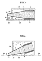
- the objectives of the present invention are achieved by a thin, electrically conductive wire 2 wound into a single-layered hollow conic coil 1, having a small end 4 and a large end 5.
- the coil is mounted in a thin-walled carrier 21 of insulating material such as plastic, with no metallic parts.
- the carrier holds the coil at an optimum orientation relative to the mounting surface of a circuit board to minimize electromagnetic reflections and resonance that would degrade microwave performance.
- the small end of the coil 4 is positioned adjacent a contact strip 17 on the circuit board.
- the wire lead 2 exits tangentially from the small end of the coil and is bonded directly to the contact strip without intermediate metallic pads.
- An optional cylindrical extension 6 on the large end of the coil provides increased low frequency inductance.
- the wide range of small to large diameters of coil windings, and careful elimination of sources of electromagnetic interference, reflections, and resonance provides an inductor that blocks a broad band of radio frequency energy while providing a direct current to pass through the coil unattenuated.
- Mounting plane of carrier This is the plane of the electrical contact surfaces on which the carrier is mounted.
- the mounting plane of the carrier is not necessarily enclosed by the carrier, but may be defined by a common cut-off plane along the bottom of the wall or walls of the carrier.
- the small end of the coil is the high-frequency, or "hot", end of the coil.
- the "hot" lead is the first lead, or the lead from the small end of the coil.
- the "cold” or grounded end is the large end of the coil.
- a microwave choke is a coil of electrically conductive wire that prevents radio frequency energy from passing through it over a range of frequencies.
- the invention is a microwave choke with flat performance to less than 0.15 DB maximum insertion loss and over 20 DB of return loss from 300 khz to 60 Ghz. It utilizes a plastic enclosure or carrier that does not substantially degrade its electrical performance. It is easily handled and positioned with automatic equipment for accurate placement, resulting in optimum performance.
- the device uses specially prepared insulated wire with the insulation removed at the ends.
- the lead 2 at the small end 4 of the coil should be free of insulation to within a distance from the first winding of the coil of no greater than twice the inner diameter of the small end of the coil. Alternately, the lead 2 should be free of insulation to within a distance from the first winding of the coil of no greater than 0.020".
- Minimal lead lengths greatly improve high frequency operation.
- Only the uninsulated ends or leads 2 and 3 of the wire are plated with tin, solder, or preferably gold.
- Gold plating has a nickel under-plate to prevent copper migration through the gold. Gold plating permits the leads to be either gap welded or thermosonically wire bonded to gold pads in addition to other bonding methods, such as reflow soldering and conductive epoxy bonding.
- the carriers shown herein permit the choke to be fully automatically positioned with extreme accuracy onto a micro-strip line.
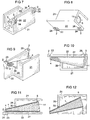
- the embodiment of FIGs 7-12 allows installation by reflow soldering or by the use of conductive epoxy on both leads 2 and 3, but this design has a somewhat reduced frequency response. The reduced response is caused by excessive material present on the small end and an extension of the hot lead along a plane perpendicular to the mounting plane.
- the carrier of FIG 13 holds both leads 2 and 3 in an unobstructed span adjacent the coil for direct bonding of both leads to respective contacts on a circuit board without intermediate metallic pads.
- the unobstructed span of each lead is insulation free.
- FIGs 1-6 allow installation of the low potential end 3 by reflow soldering or conductive epoxy but permits the high potential end 2 to be attached by gap welding or ultrasonic bonding. All excess material applied to the high potential end is eliminated when this end is bonded without the use of solder or epoxy.
- the carrier 21 is preferably made of high-temperature thermoplastic with low radio frequency loss that is resistant to solder heat.
- the presently preferred material is liquid crystal polymer (LCP) with a melting point of about 750 degrees Fahrenheit.
- LCP liquid crystal polymer
- the coil 1 is attached inside the enclosure by a stripe of epoxy 27, or may be suspended by the leads as in FIG 13.
- the epoxy stripe does not extend to the small end 4 of a conical inductor, which is electrically sensitive.
- the epoxy stripe should not approach the first winding of a conical coil to within a distance of three inner diameters of the small end of the coil, preferably greater. This end of the coil is free of excess material of any type, since any excess material near this end will degrade performance.
- the leads 2 and 3 are precisely positioned on the carrier by grooves in lead-holding areas 23 and 26 on the carrier, and are then plastic-welded into position.
- the carrier plastic is deformed and surrounds the leads by a heated spot welding tip that locks the lead within the plastic 24. This eliminates the need for any metallic parts on the carrier.
- the carrier preferably has an asymmetric shape with a flat top. This enables orientation by a vibratory feed mechanism that presents a properly oriented choke to a vacuum pickup for positioning.
- the vacuum pickup places the choke in its exact final location on a circuit. This process is referenced in the electronic industry as "pick and place”.
- the carrier dimensions preferably are repeatable to better than 0.0005 inch by fabrication in a high precision mold. High carrier accuracy allows the chokes to be positioned to plus or minus 0.001", which is often necessary for repeatable performance.
- the carrier walls are preferably about 0.007 inch thick, which is about twice as thick as a sheet of paper. Alternately, the carrier preferably has a typical wall thickness no greater than the interior diameter of the small end of the coil.
- the carrier supports the inductor, and preferably positions it at an oblique angle to the mounting plane 28 of the carrier, and thus to the micro-strip line 17 when installed. This angle should be such that the circumference of the small end 4 of the coil is nearly tangent to the mounting plane 28 of the carrier.
- the small end of the coil should preferably be separated from the mounting plane of the carrier by less than 1/2 of the inner radius of the small end of the coil.
- the first lead 2 should preferably reach the mounting plane of the carrier within a distance from the first winding of less than one radius of the small end of the coil.
- the large end of the coil 5 should preferably be separated from the mounting plane by a distance D of at least half the radius of the large end of the coil.
- the carrier preferably provides an unobstructed span of at least the hot lead 2 adjacent to the coil along the mounting plane, so this lead can be electrically bonded directly to a contact on a circuit board.
- the leads are placed so they are underneath the outside edges of the enclosure and are secured by plastic welding, either to an outside wall of the enclosure or to a bottom edge of the enclosure.
- This unique geometry minimizes the dielectric loss effect of the enclosure material on the electrical characteristics of the coil.
- Conventional components have a metallic pad on a top surface of a carrier or enclosure, and leads are attached to this pad. This causes dielectric properties of the carrier to reduce the performance of the component, and causes excessive stray capacitance inherent in the large area geometry of a conventional contact pad.
- a lead is attached to a bottom surface of a pad, but the pad is generally large and introduces considerable stray capacitance and dielectric loss.
- the ultra thin walls of the present carrier have negligible mass and negligible stray effects.
- the total absence of a conventional metal bonding pad eliminates stray effects associated with conventional designs. Since the ends of the leads in the present design are plastic-welded into the walls of the carrier, no conductive material is added to make a large bonding pad. The wire is thus bonded to the micro strip with less than one tenth of the area of the smallest conventional bonding pad.
- the first lead 2 is preferably bonded to the micro strip at a distance from the first winding of the coil no greater than twice the inner diameter of the small end of the coil. Alternately, the first lead 2 is preferably bonded to the micro strip at no more than .020 inch from the small end of the coil. Closer bonding distance is better for high frequency response.
- the carrier is preferably made of thermoplastic with a melting point above 600 degrees Fahrenheit, which is higher than the melting point of solder. Tiny solder balls mixed with flux are commonly known as "solder paste". Drops of solder paste can be automatically deposited on contact points on a circuit board where the choke leads are to be bonded. The carrier is then placed on the circuit board with the choke leads in the respective drops. A carrier with a flat top allows vacuum pickup and precise placement on a circuit board by automated equipment. The contacts on the circuit board are then heated to the melting point of solder to bond the leads directly to the contacts on the circuit board close to the coil.
- Each of the following features individually improves the usable frequency range of a microwave choke. These features can be beneficially used in various combinations, some of which extend the useable frequency range by several orders of magnitude over existing chokes.
- the wire lead 2 is preferably bonded to the micro-strip 17 by gap welding, which adds no extra material to cause abrupt geometry changes that result in standing waves. Gap welding fuses the gold plated wire lead 2 into the metal of the micro-strip 17 without additional bonding material, thus providing reduced bond size and a smoother transition. Additionally, it provides a gold-to-gold bond, which is more reliable and withstands higher temperatures than other bonds.
- the micro-strip 17 typically has a 0.010" wide trace on top of a dielectric substrate 15 with a conductive ground plate 16 on the bottom of the substrate. Conventional components contain metallic bonding pads that are typically at least 0.010" square and do not align perfectly with the micro-strip. This results in reflections of energy and reduced performance over the frequency range.
- the carrier is secured to the circuit board with non-conductive epoxy 32 in areas away from the leads.
- Low frequency response of a hollow conic coil is improved by inserting a core of magnetic material, such as ferrite. However, this can reduce the high-frequency response. High-frequency response is best maintained if the magnetic material is fine-grained and not easily permanently magnetized.
- the grain size is preferably 1 micron or smaller. This small grain size can currently be produced in both powdered iron and ferrite. Powdered iron is preferred because ferrite tends to retain permanent magnetism. So-called "soft" ferrites retain less magnetism than "hard” ferrites. Soft ferrites are preferred if ferrite is used.
- the low frequency range of the choke can be extended by providing a cylindrical extension 6 integrally formed on the large end of the conic inductor.
- This extension is filled with a ferrite rod.
- Plural layers of wire are wound directly over the ferrite portion of the core.
- the cylindrical extension does not require fine-grained material, a less expensive ferrite with a grain size such as 5 microns can be used.
- the conic portion of the coil can have a different core material than the cylindrical extension. This provides design options to maximize bandwidth and minimize cost, depending on the available production cost of a different core for each section of the choke versus a single core for both sections from fine-grained magnetic material.
- a difficulty with fabricating and handling microwave chokes is that they use very fine wire.
- the wire can be finer than a human hair, or from about 0.0008 to 0.0015 inch in diameter. This makes them extremely fragile. It is difficult to place the device accurately in a circuit. However, placement is critical to optimum performance. A placement error of 0.001 inch will cause a measurable degradation in performance. Automatic precise placement is enabled with the carrier design as previously described.
- the main design considerations for which geometry of the choke should be selected are 1) the physical size limitations of the choke; and 2) the current carrying capacity requirements. There are tradeoffs in construction. Current carrying capacity is determined by the wire diameter, but larger wire makes the device physically larger and reduces its high frequency range. Reducing the diameter of the small end of the coil causes the choke to block higher frequencies. Raising inductance at the large end of the coil by including a cylindrical portion improves blocking of lower frequencies.
- a choke made with #36 gauge (AWG) wire provides about 600 ma current capacity. If the small end of the coil is 0.016" I.D., the choke will operate up to about 12 Ghz. This choke can be mounted flat against a circuit board without significant performance loss.
- a choke with #47 gauge (AWG) wire provides about 100 ma current capacity. If the small end of the coil is 0.005" I.D., the choke operates up to about 40 Ghz if the first lead is directly bonded to the respective contact on the circuit board within 0.005" of the first winding of the small end of the coil. If the bonding distance is 0.010", the choke operates up to about 35 Ghz. If the bonding distance is 0.020", the choke operates up to about 31 Ghz. The large end of the coil should be separated by a distance D from the mounting plane of the circuit board as described below.
- the large end of the coil should be separated by a distance D from the mounting plane of the circuit board as described below.
- the angle of the coil relative to the surface of the circuit board effects the high frequency performance of the choke. Up to 12 Ghz the coil can rest on the circuit board with little effect. Above 12 Ghz the high frequency response improves if the coil is set at an angle to the circuit board. This is accomplished by mounting the large end of the coil above the mounting plane 28 of the carrier by a distance D of at least half the inner radius of the large end of the coil or more, depending on physical space available and bandwidth desired.
- the cylindrical part of the coil preferably has 3 layers. This provides high inductance in a shorter cylindrical coil length as compared to a single layer.
- the cylindrical extension is approximately half the length of the conic coil. The use of two layers in the cylindrical extension is not recommended, because it lowers the self-resonant frequency of the coil. Any odd number of layers from 3 and up are best. Use of multiple layers on the small end of the coil is not recommended because it reduces the high frequency response.
- the outrigger 25 can be snapped off. If the conductive weld 7 of the first lead 2 to the micro-strip is made properly, the wire breaks just beyond the weld (FIGs 5 and 6), leaving the weld intact. Removing the outrigger eliminates stray electromagnetic effects caused by it and the extension of the wire beyond the weld to the outrigger. The outrigger can be snapped off with tweezers using a twisting motion, and the wire will break off just beyond the weld.
- microelectronic component assembly it is a customary procedure to pull off the "pigtail" (wire extending beyond a weld) since pulling of the pigtail is the most common test for a good weld.
- the integrity of the weld is tested while simultaneously improving the microwave performance of the device. Additionally, the valuable space occupied by the outrigger can then be used for mounting other components on the micro-strip.
- the carrier is shown as box-like, but it can optionally be other shapes, including smoothly curved shapes. It can have flat sides angled to follow the conic sides of the coil, appearing trapezoidal in a top view. In any case, it preferably has at least a flat top and an asymmetric shape to enable automatic handling.
- the microwave choke technology described herein has applicability for blocking broadband microwave energy in electronic circuits, such as in power supplies in amplifiers, signal generators, filters, and laser drivers.
- the carrier technology described herein for microwave chokes can also be used for mounting other electronics components onto circuits.
- Any small electronics component with leads such as a resistor, capacitor, or switch, can be assembled in a totally electrically non-conductive carrier, with each lead from the component having an end attached to the carrier by non-metallic means. At least one of the leads from the component has an unobstructed length between the end of the lead and the component for direct attachment to a contact in an electronics circuit as previously described.
- FIG 13 shows an example of this configuration. This figure can be seen as either a choke or a resistor.
- the carrier technology described herein not only increases the frequency response of electronic devices, but also substantially reduces costs of electronic devices designed for automatic circuit assembly.
Landscapes
- Engineering & Computer Science (AREA)
- Power Engineering (AREA)
- Microelectronics & Electronic Packaging (AREA)
- Manufacturing & Machinery (AREA)
- Coils Or Transformers For Communication (AREA)
- Structures For Mounting Electric Components On Printed Circuit Boards (AREA)
Applications Claiming Priority (4)
| Application Number | Priority Date | Filing Date | Title |
|---|---|---|---|
| US660339 | 2000-09-14 | ||
| US09/660,339 US6236289B1 (en) | 2000-09-14 | 2000-09-14 | Broadband microwave choke with a hollow conic coil filled with powdered iron in a leadless carrier |
| US09/834,526 US6344781B1 (en) | 2000-09-14 | 2001-04-14 | Broadband microwave choke and a non-conductive carrier therefor |
| US834526 | 2001-04-14 |
Publications (2)
| Publication Number | Publication Date |
|---|---|
| EP1189247A2 true EP1189247A2 (de) | 2002-03-20 |
| EP1189247A3 EP1189247A3 (de) | 2002-07-24 |
Family
ID=27098058
Family Applications (1)
| Application Number | Title | Priority Date | Filing Date |
|---|---|---|---|
| EP01307197A Withdrawn EP1189247A3 (de) | 2000-09-14 | 2001-08-23 | Breitbandige Mikrowellendrossel und oberflächenmontierter Träger |
Country Status (3)
| Country | Link |
|---|---|
| US (1) | US6344781B1 (de) |
| EP (1) | EP1189247A3 (de) |
| WO (1) | WO2002023559A1 (de) |
Cited By (2)
| Publication number | Priority date | Publication date | Assignee | Title |
|---|---|---|---|---|
| US7259651B2 (en) | 2005-02-19 | 2007-08-21 | Tyco Electronics Uk Ltd. | Energy storage coil |
| US8072773B2 (en) | 2008-04-04 | 2011-12-06 | John Mruz | Ultra-wideband assembly system and method |
Families Citing this family (15)
| Publication number | Priority date | Publication date | Assignee | Title |
|---|---|---|---|---|
| US7259688B2 (en) * | 2000-01-24 | 2007-08-21 | Shell Oil Company | Wireless reservoir production control |
| US6633236B2 (en) * | 2000-01-24 | 2003-10-14 | Shell Oil Company | Permanent downhole, wireless, two-way telemetry backbone using redundant repeaters |
| US7322410B2 (en) * | 2001-03-02 | 2008-01-29 | Shell Oil Company | Controllable production well packer |
| US7132919B2 (en) * | 2003-10-30 | 2006-11-07 | Agilent Technologies, Inc. | High-frequency inductor with integrated contact |
| US7518463B2 (en) * | 2004-12-23 | 2009-04-14 | Agilent Technologies, Inc. | Circuit assembly with conical inductor |
| JP4498258B2 (ja) * | 2005-10-13 | 2010-07-07 | 富士通オプティカルコンポーネンツ株式会社 | コイルパッケージ |
| NO326643B1 (no) * | 2006-12-08 | 2009-01-26 | Roxar Flow Measurement As | Kraftforsyningssystem for nedihullsnettverk. |
| JP4591572B2 (ja) * | 2008-08-05 | 2010-12-01 | セイコーエプソン株式会社 | コイルアセンブリおよびスイッチング型電源装置 |
| CN103839661B (zh) * | 2014-03-12 | 2017-06-20 | 华为技术有限公司 | 一种锥形电感、印刷电路板以及光模块 |
| CN106054412B (zh) * | 2016-05-10 | 2018-10-09 | 中国科学院半导体研究所 | 表贴式无自激的偏置网络 |
| US10080289B2 (en) * | 2016-07-20 | 2018-09-18 | Macom Technology Solutions Holdings, Inc. | Method and apparatus for electrical device placement using a pedestal |
| US20210067196A1 (en) * | 2019-08-27 | 2021-03-04 | Atx Networks (Toronto) Corp. | Low Insertion Loss Network Device Having an Extended RF Spectrum |
| JP7297655B2 (ja) * | 2019-12-13 | 2023-06-26 | 株式会社東芝 | スキャニングコイル、スキャニング磁石およびスキャニングコイルの製造方法 |
| JP2023018770A (ja) * | 2021-07-28 | 2023-02-09 | Tdk株式会社 | コイル部品 |
| US12300610B2 (en) | 2021-12-15 | 2025-05-13 | Macom Technology Solutions Holdings, Inc. | Method and apparatus for electromigration reduction |
Family Cites Families (18)
| Publication number | Priority date | Publication date | Assignee | Title |
|---|---|---|---|---|
| US2351604A (en) * | 1941-01-18 | 1944-06-20 | Nat Company Inc | Inductance coil |
| US2442776A (en) * | 1944-11-08 | 1948-06-08 | Thomas A Newkirk | Radio-frequency choke coil |
| US2547412A (en) * | 1945-05-23 | 1951-04-03 | Winfield W Salisbury | High-frequency mixer |
| US3076947A (en) * | 1960-11-01 | 1963-02-05 | Hughes Aircraft Co | Low pass filter |
| US3601728A (en) * | 1969-10-03 | 1971-08-24 | Navcor Inc | Printed circuit key improvement |
| US3713037A (en) * | 1970-10-07 | 1973-01-23 | Gen Microwave Corp | Variable microwave attenuator |
| US4236127A (en) * | 1977-04-13 | 1980-11-25 | Pyrohm, Inc. | Electrical frequency responsive structure |
| JPS6189610A (ja) * | 1984-10-09 | 1986-05-07 | Matsushita Electric Ind Co Ltd | インダクタ |
| DE3602759C2 (de) * | 1986-01-30 | 1995-11-09 | Vogt Electronic Ag | Induktives SMD-Bauelement |
| DE3615307C2 (de) * | 1986-05-06 | 1994-07-07 | Johann Leonhard Huettlinger | Spule für automatische SMD-Bestückung |
| US5253145A (en) * | 1992-01-24 | 1993-10-12 | Pulse Engineering, Inc. | Compliant cantilever surface mount lead |
| JPH05299252A (ja) * | 1992-04-22 | 1993-11-12 | Tokin Corp | 面実装形チョークコイル |
| JP2799687B2 (ja) * | 1995-04-19 | 1998-09-21 | 東邦亜鉛株式会社 | 表面実装型チョークコイル |
| JPH0955320A (ja) * | 1995-08-10 | 1997-02-25 | Tokin Corp | コモンモードチョークコイル |
| US5805431A (en) * | 1996-01-17 | 1998-09-08 | Synergy Microwave Corporation | Surface Mountable transformer |
| US5838215A (en) * | 1996-02-05 | 1998-11-17 | Motorola, Inc. | RF choke with a low Q core formed by sintering ferrous and ferric oxides |
| US6094110A (en) * | 1998-11-18 | 2000-07-25 | National Electronic Devices, Inc. | RF choke with windings located at two different core diameters |
| US6236289B1 (en) * | 2000-09-14 | 2001-05-22 | Stephen Amram Slenker | Broadband microwave choke with a hollow conic coil filled with powdered iron in a leadless carrier |
-
2001
- 2001-04-14 US US09/834,526 patent/US6344781B1/en not_active Expired - Lifetime
- 2001-06-26 WO PCT/US2001/020397 patent/WO2002023559A1/en not_active Ceased
- 2001-08-23 EP EP01307197A patent/EP1189247A3/de not_active Withdrawn
Non-Patent Citations (1)
| Title |
|---|
| None * |
Cited By (5)
| Publication number | Priority date | Publication date | Assignee | Title |
|---|---|---|---|---|
| US7259651B2 (en) | 2005-02-19 | 2007-08-21 | Tyco Electronics Uk Ltd. | Energy storage coil |
| US8072773B2 (en) | 2008-04-04 | 2011-12-06 | John Mruz | Ultra-wideband assembly system and method |
| US8797761B2 (en) | 2008-04-04 | 2014-08-05 | John Mruz | Ultra-wideband assembly system and method |
| US9854665B2 (en) | 2008-04-04 | 2017-12-26 | American Technical Ceramics Corp. | Ultra-wideband assembly system and method |
| US10165675B2 (en) | 2008-04-04 | 2018-12-25 | American Technical Ceramics Corp. | Ultra-wideband assembly system and method |
Also Published As
| Publication number | Publication date |
|---|---|
| WO2002023559A1 (en) | 2002-03-21 |
| US6344781B1 (en) | 2002-02-05 |
| EP1189247A3 (de) | 2002-07-24 |
Similar Documents
| Publication | Publication Date | Title |
|---|---|---|
| US6344781B1 (en) | Broadband microwave choke and a non-conductive carrier therefor | |
| EP1403887B1 (de) | Spulenfilter und verfahren zu seiner herstellung | |
| US7612641B2 (en) | Simplified surface-mount devices and methods | |
| JP4532167B2 (ja) | チップコイルおよびチップコイルを実装した基板 | |
| GB2083952A (en) | Microcoil Assembly | |
| JPH11238634A (ja) | 面実装型コイル部品 | |
| JP2002110428A (ja) | 巻線型コモンモードチョークコイル | |
| US6236289B1 (en) | Broadband microwave choke with a hollow conic coil filled with powdered iron in a leadless carrier | |
| JP2018533326A (ja) | Hf及びlf動作のためのアンテナ装置 | |
| CN112466597B (zh) | 电感器部件 | |
| US20240428985A1 (en) | Circuit device and filter circuit | |
| KR101892689B1 (ko) | 칩 전자부품 및 칩 전자부품의 실장 기판 | |
| US7132919B2 (en) | High-frequency inductor with integrated contact | |
| EP0696878A2 (de) | Mikrowellenvorrichtung | |
| JPH09326317A (ja) | マイクロ波インダクタコイル | |
| US11869704B2 (en) | Coil device | |
| JP2001509954A (ja) | インダクタンス素子のフェライト鉄心に規定された電位を設定する及び/又は磁界によって誘導される損失によるインダクタンス素子の減衰を少なくする装置 | |
| JPH0636930A (ja) | 電気デバイス | |
| CN113744975B (zh) | 线圈组件 | |
| KR20230143842A (ko) | 코일 부품 | |
| US20210296046A1 (en) | Coil component and electronic device | |
| US20180286553A1 (en) | Coil device | |
| JP3241102B2 (ja) | ノイズフィルタ | |
| KR102004240B1 (ko) | 칩 전자부품 및 칩 전자부품의 실장 기판 | |
| KR102130679B1 (ko) | 칩 전자부품 |
Legal Events
| Date | Code | Title | Description |
|---|---|---|---|
| PUAI | Public reference made under article 153(3) epc to a published international application that has entered the european phase |
Free format text: ORIGINAL CODE: 0009012 |
|
| AK | Designated contracting states |
Kind code of ref document: A2 Designated state(s): AT BE CH CY DE DK ES FI FR GB GR IE IT LI LU MC NL PT SE TR |
|
| AX | Request for extension of the european patent |
Free format text: AL;LT;LV;MK;RO;SI |
|
| PUAL | Search report despatched |
Free format text: ORIGINAL CODE: 0009013 |
|
| RIC1 | Information provided on ipc code assigned before grant |
Free format text: 7H 01F 17/04 A, 7H 01F 27/29 B, 7H 05K 3/34 B |
|
| AK | Designated contracting states |
Kind code of ref document: A3 Designated state(s): AT BE CH CY DE DK ES FI FR GB GR IE IT LI LU MC NL PT SE TR |
|
| AX | Request for extension of the european patent |
Free format text: AL;LT;LV;MK;RO;SI |
|
| 17P | Request for examination filed |
Effective date: 20020911 |
|
| AKX | Designation fees paid |
Designated state(s): AT BE CH CY DE DK ES FI FR GB GR IE IT LI LU MC NL PT SE TR |
|
| 17Q | First examination report despatched |
Effective date: 20050617 |
|
| GRAP | Despatch of communication of intention to grant a patent |
Free format text: ORIGINAL CODE: EPIDOSNIGR1 |
|
| STAA | Information on the status of an ep patent application or granted ep patent |
Free format text: STATUS: THE APPLICATION IS DEEMED TO BE WITHDRAWN |
|
| 18D | Application deemed to be withdrawn |
Effective date: 20070905 |