EP1189015B1 - Procédé et appareil pour mesurer l'extension axiale d'un arbre tournant - Google Patents
Procédé et appareil pour mesurer l'extension axiale d'un arbre tournant Download PDFInfo
- Publication number
- EP1189015B1 EP1189015B1 EP01119223A EP01119223A EP1189015B1 EP 1189015 B1 EP1189015 B1 EP 1189015B1 EP 01119223 A EP01119223 A EP 01119223A EP 01119223 A EP01119223 A EP 01119223A EP 1189015 B1 EP1189015 B1 EP 1189015B1
- Authority
- EP
- European Patent Office
- Prior art keywords
- rotary shaft
- sensor
- measuring
- axial elongation
- mark
- Prior art date
- Legal status (The legal status is an assumption and is not a legal conclusion. Google has not performed a legal analysis and makes no representation as to the accuracy of the status listed.)
- Expired - Lifetime
Links
Images
Classifications
-
- G—PHYSICS
- G01—MEASURING; TESTING
- G01B—MEASURING LENGTH, THICKNESS OR SIMILAR LINEAR DIMENSIONS; MEASURING ANGLES; MEASURING AREAS; MEASURING IRREGULARITIES OF SURFACES OR CONTOURS
- G01B7/00—Measuring arrangements characterised by the use of electric or magnetic techniques
- G01B7/16—Measuring arrangements characterised by the use of electric or magnetic techniques for measuring the deformation in a solid, e.g. by resistance strain gauge
- G01B7/24—Measuring arrangements characterised by the use of electric or magnetic techniques for measuring the deformation in a solid, e.g. by resistance strain gauge using change in magnetic properties
-
- G—PHYSICS
- G01—MEASURING; TESTING
- G01B—MEASURING LENGTH, THICKNESS OR SIMILAR LINEAR DIMENSIONS; MEASURING ANGLES; MEASURING AREAS; MEASURING IRREGULARITIES OF SURFACES OR CONTOURS
- G01B11/00—Measuring arrangements characterised by the use of optical techniques
- G01B11/16—Measuring arrangements characterised by the use of optical techniques for measuring the deformation in a solid, e.g. optical strain gauge
-
- G—PHYSICS
- G01—MEASURING; TESTING
- G01B—MEASURING LENGTH, THICKNESS OR SIMILAR LINEAR DIMENSIONS; MEASURING ANGLES; MEASURING AREAS; MEASURING IRREGULARITIES OF SURFACES OR CONTOURS
- G01B21/00—Measuring arrangements or details thereof, where the measuring technique is not covered by the other groups of this subclass, unspecified or not relevant
- G01B21/32—Measuring arrangements or details thereof, where the measuring technique is not covered by the other groups of this subclass, unspecified or not relevant for measuring the deformation in a solid
-
- G—PHYSICS
- G01—MEASURING; TESTING
- G01B—MEASURING LENGTH, THICKNESS OR SIMILAR LINEAR DIMENSIONS; MEASURING ANGLES; MEASURING AREAS; MEASURING IRREGULARITIES OF SURFACES OR CONTOURS
- G01B7/00—Measuring arrangements characterised by the use of electric or magnetic techniques
- G01B7/003—Measuring arrangements characterised by the use of electric or magnetic techniques for measuring position, not involving coordinate determination
-
- G—PHYSICS
- G01—MEASURING; TESTING
- G01B—MEASURING LENGTH, THICKNESS OR SIMILAR LINEAR DIMENSIONS; MEASURING ANGLES; MEASURING AREAS; MEASURING IRREGULARITIES OF SURFACES OR CONTOURS
- G01B7/00—Measuring arrangements characterised by the use of electric or magnetic techniques
- G01B7/16—Measuring arrangements characterised by the use of electric or magnetic techniques for measuring the deformation in a solid, e.g. by resistance strain gauge
- G01B7/22—Measuring arrangements characterised by the use of electric or magnetic techniques for measuring the deformation in a solid, e.g. by resistance strain gauge using change in capacitance
Definitions
- the present invention relates to a rotary shaft axial elongation measuring method and a device therefor, such as for a gas turbine or steam turbine rotor shaft, that elongates in the axial direction.
- a rotor shaft of a gas turbine or steam turbine causes an axial elongation according to temperature change
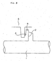
- One example of the prior art to measure the axial elongation of a rotary shaft with such an object is to use a gap sensor to detect a gap caused by the axial elongation, as shown in Fig. 5.
- numeral 1 designates a rotary shaft and this rotary shaft 1 is provided with a target face 2 for measuring the axial elongation.
- a gap sensor 4 is arranged so as to oppose the target face 2.
- the gap sensor 4 is fitted to a stationary part 6.
- the gap sensor 4 measures a gap 8 between the target face 2 and the sensor 4 and, by the change of this gap 8, the axial elongation of the rotary shaft 1 is measured.
- the elongation of the rotary shaft 1 is directly measured by the gap sensor 4 relative to the stationary part 6. Therefore, in case the axial elongation of the rotary shaft 1 is large, it is necessary to measure the gap 8 over a wide range, but to measure the gap 8 by the gap sensor 4 over the wide range often results in the less accuracy.
- the gap sensor 4 is provided in the axial directional space around the rotary shaft 1 where the gap 8 to be measured exists, a certain space is required in the axial direction of the rotary shaft 1 for installing the gap sensor 4.
- DE 39 08 248 A discloses a method and device for measuring an axial elongation of a rotary shaft in which a first mark is provided at the outer peripheral surface of the rotary shaft so as to extend parallel to the rotational axis and a second mark is arranged in an inclined angle thereto.
- a sensor is provided opposed to the surface of the rotary shaft so as to detect the passing of the marks upon rotation of the shaft.
- the detection signals are used as start and stop signals for a time measuring device in order to detect the interval between the signals representing the passing of the first and second marks.
- a ratio of the interval between two consecutive detections of the same mark and the interval between the detections of consecutive marks are used.
- JP 63313007 A discloses another method and device for measuring the axial elongation of a rotary shaft in which similar marks are used on the outer peripheral surface of the rotary shaft.
- two sensors are provided to respectively detect the passing of one of the marks and the elongation quantity of the shaft is calculated from the time difference from a measurement time interval determined by the signal from the sensor sensing the reference mark extending in the axial direction and the measurement time interval determined by the signal from the second sensor sensing the inclined mark.
- the present invention provides a rotary shaft axial elongation measuring method for measuring an axial elongation of a rotary shaft as defined in claim 1 and a corresponding measuring device as defined in claim 2.
- the circumferential directional position of the measuring mark line relative to the position of the reference mark line changes according to the axial directional position thereof.
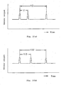
- the sensor generates the pulses when the reference mark and the measuring mark pass by the sensor following the rotation of the rotary shaft and hence, if the axial directional position of the rotary shaft opposing the sensor changes due to the axial elongation of the rotary shaft, then the interval of the pulses generated by the sensor differs. Consequently, by measuring the change in the interval of the pulses generated by the sensor, the axial elongation of the rotary shaft can be measured.
- the steps are simplified such that the reference mark, and the measuring mark arranged inclinedly relative to the axial direction of the rotary shaft, are provided on the rotational surface of the rotary shaft, the axial elongation of which is to be measured, and the sensor is arranged fixedly so as to oppose the rotational surface of the rotary shaft for generating pulses upon passing by of the mentioned marks following the rotation of the rotary shaft.
- the gap between the sensor and the rotational surface of the rotary shaft opposing the sensor does not change substantially by the axial elongation of the rotary shaft and the accuracy of measuring the axial elongation by the sensor is in no case reduced by the sizes of the axial elongation.
- such a device is provided as is able to measure the axial elongation of the rotary shaft based on the axial elongation measuring method of the present invention as mentioned above.
- the gap between the sensor and the rotational surface is constant regardless of sizes of the axial elongation of the rotary shaft and measuring of the axial elongation with a high accuracy can be performed.
- the axial elongation measuring device of the present invention as the sensor may be arranged with a predetermined gap being maintained between itself and the rotational surface of the rotary shaft, only a narrow space is required for measuring the axial elongation regardless of sizes of the axial elongation.
- the reference mark and the measuring mark provided on the rotational surface of the rotary shaft in the axial elongation measuring device of the present invention may be two marks provided such that an interval between them in the circumferential direction of the rotary shaft differs according to the axial directional position of the rotary shaft. These two marks may be two grooves or two wire members both provided in a turned V shape.
- the measuring mark used in the axial elongation measuring device of the present invention may be a groove or a wire member both provided in a spiral shape on the rotational surface of the rotary shaft.
- the axial elongation measuring device of the present invention may be of a simple construction that is made easily and less costly.
- the sensor used in the axial elongation measuring method and device of the present invention may be an ordinary gap sensor, such as a capacitance type gap sensor or eddy current gap sensor, or may be a photoelectric sensor that generates a pulse signal upon passing of a mark provided on the rotational surface.
- the measuring device that can be easily installed for enabling the measuring of the axial elongation is provided.
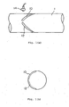
- numerals 10 and 12 designate grooves, that are provided in a rotational outer circumferential surface of a rotary shaft 1 so as to oppose one another inclinedly in a turned V shape.
- the grooves 10, 12, opposing one another extend inclinedly in an axial direction of the rotary shaft 1 and an interval between the grooves 10, 12 changes according to the axial directional position thereof, so that a construction is made such that one of the grooves 10, 12 constitutes a reference mark as hereinafter referred to and the other constitutes a measuring mark as hereinafter referred to.
- Numeral 14 designates a sensor, that is arranged so as to oppose the rotational outer circumferential surface of the rotary shaft 1.
- This sensor 14 may be a sensor, such as a capacitance type gap sensor, eddy current gap sensor or photoelectric sensor, that generates a pulse or pulse signal according to a change in a capacitance, eddy current or reflection of light following a change in a gap between the sensor 14 and the rotational outer circumferential surface of the rotary shaft 1 when the grooves 10, 12 pass by the sensor 14 by the rotation of the rotary shaft 1.
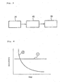
- Fig. 3 is a block diagram showing an entire construction of the axial elongation measuring device, wherein the pulse interval ratio of the pulses detected by the sensor 14 is sent to a data processing part 16 and the axial elongation obtained at the data processing part 16 is displayed at a display part 18.
- the grooves 10, 12 of the rotary shaft 1 may be provided in the outer circumferential surface of the rotary shaft 1 within the range of 1/2 or less of the entire outer circumference as shown in Fig. 1(b) and then, if the ratio t1/t2 is more than 0.5 (t1/t2>0.5), the axial elongation and the ratio t1/t2 can be decided correspondingly as (1-t1/t2) and thereby the data processing can be simplified.
- Fig. 4 shows the accuracy of the present invention and 2 shows the state where the measuring accuracy becomes lower as the gap between the sensor and the object to be measured becomes larger by the axial elongation as in the case shown in Fig. 5.
- a wire member such as a wire made of aluminum or stainless steel, may be fitted instead as a mark by spot welding or the like so as to form a projection on the rotational surface.
Landscapes
- Physics & Mathematics (AREA)
- General Physics & Mathematics (AREA)
- Measurement Of Length, Angles, Or The Like Using Electric Or Magnetic Means (AREA)
- Length Measuring Devices With Unspecified Measuring Means (AREA)
- Length Measuring Devices By Optical Means (AREA)
Claims (5)
- Procédé de mesure de l'allongement axial d'un arbre tournant comprenant les stades dans lesquels:on ménage un repère (10) de référence et un repère (12) de mesure sur une surface de rotation de l'arbre (1) tournant de façon à ce que le repère (10) de référence et le repère (12) de mesure soient opposés l'un à l'autre, s'étendent de manière inclinée dans une direction axiale de l'arbre (1) tournant, etde manière à ce qu'un intervalle entre les repères (10,12) change en fonction de leur position en direction axiale;on dispose un capteur (14) de manière fixe de manière à ce qu'il soit en opposition à la surface de rotation de l'arbre (1) tournant, le capteur (14) engendrant des impulsions lors du passage sur les repères (10,12), faisant suite à une rotation de l'arbre (1) tournant;on mesure l'allongement axial de l'arbre (1) tournant à partir d'une variation du rapport entre un intervalle (t1, t12)des impulsions engendrées par le capteur (14) après avoir passé sur le repère (10) de référence et le repère (12) de mesure etun intervalle (t2, t22) des impulsions représentant une rotation de l'arbre (1) tournant.
- Dispositif de mesure de l'allongement axial de l'arbre tournant, comprenant:l'arbre (1)ayant un repère (10) de référence et un repère (12) de mesure prévus sur une surface de rotation de l'arbre (1) tournant, le repère (10) de référence et le repère (12) de mesure étant disposés de manière à ce que le repère (10) de référence et le repère (12) de mesure soient en opposition l'un à l'autre, s'étendent de manière inclinée et de manière à ce que l'intervalle entre les repères (10, 12) change en fonction de leur position en direction axiale,un capteur (14) disposé de manière fixe de manière à ce qu'il soit en opposition à la surface de rotation de l'arbre (1) tournant, le capteur (14) engendrant des impulsions lors du passage sur les repères (10,12), faisant suite à une rotation de l'arbre (1) tournant; etune partie (16) de traitement de données, conçue pour mesurer l'allongement axial de l'arbre(1) tournant à partir d'une variation du rapport entre un intervalle (t1, t12) des impulsions engendrées par le capteur (14) après avoir passé sur le repère (10) de référence et le repère (12) de mesure etun intervalle (t2, t22) des impulsions représentant une rotation de l'arbre (1) tournant.
- Dispositif de mesure de l'allongement axial d'un arbre tournant, tel que revendiqué à la revendication 2, dans lequel les deux repères sont deux rainures (10, 12).
- Dispositif tel que revendiqué à la revendication 2, dans lequel les deux repères sont deux éléments filaires.
- Dispositif tel que revendiqué aux revendications 2 à 4, dans lequel le capteur (14) est l'un quelconque des capteurs d'intervalle du type capacitif, d'un capteur d'intervalle du type à courant de Foucault et d'un capteur photoélectrique.
Applications Claiming Priority (2)
| Application Number | Priority Date | Filing Date | Title |
|---|---|---|---|
| JP2000281826 | 2000-09-18 | ||
| JP2000281826A JP2002090138A (ja) | 2000-09-18 | 2000-09-18 | 回転軸の軸伸び量計測方法及び計測装置 |
Publications (2)
| Publication Number | Publication Date |
|---|---|
| EP1189015A1 EP1189015A1 (fr) | 2002-03-20 |
| EP1189015B1 true EP1189015B1 (fr) | 2006-10-18 |
Family
ID=18766428
Family Applications (1)
| Application Number | Title | Priority Date | Filing Date |
|---|---|---|---|
| EP01119223A Expired - Lifetime EP1189015B1 (fr) | 2000-09-18 | 2001-08-09 | Procédé et appareil pour mesurer l'extension axiale d'un arbre tournant |
Country Status (5)
| Country | Link |
|---|---|
| US (1) | US6807870B2 (fr) |
| EP (1) | EP1189015B1 (fr) |
| JP (1) | JP2002090138A (fr) |
| CA (1) | CA2355496C (fr) |
| DE (1) | DE60123899D1 (fr) |
Families Citing this family (16)
| Publication number | Priority date | Publication date | Assignee | Title |
|---|---|---|---|---|
| US7121012B2 (en) * | 1999-12-14 | 2006-10-17 | Voecks Larry A | Apparatus and method for measuring and controlling pendulum motion |
| US7845087B2 (en) * | 1999-12-14 | 2010-12-07 | Voecks Larry A | Apparatus and method for measuring and controlling pendulum motion |
| DE102006059439B4 (de) * | 2006-12-15 | 2018-01-25 | Prüftechnik Dieter Busch AG | Verfahren und Vorrichtung zur dynamischen Messung der axialen Deformation einer rotierenden Hohlwelle |
| WO2009048970A1 (fr) * | 2007-10-09 | 2009-04-16 | Schweitzer Engineering Laboratories, Inc. | Dispositif de surveillance d'un angle de puissance |
| US8042412B2 (en) * | 2008-06-25 | 2011-10-25 | General Electric Company | Turbomachinery system fiberoptic multi-parameter sensing system and method |
| FR2994262B1 (fr) * | 2012-08-02 | 2014-08-29 | Turbomeca | Mesure du fluage d'une pale de turbine |
| US8912792B2 (en) | 2012-08-24 | 2014-12-16 | Schweitzer Engineering Laboratories, Inc. | Systems and methods for rotor angle measurement in an electrical generator |
| WO2014134129A1 (fr) | 2013-02-26 | 2014-09-04 | Fuller Kenneth A | Procédés et appareil de mesure de décalage axial d'arbre à l'intérieur de moteurs à turbine à gaz |
| DE102014205291A1 (de) * | 2014-03-21 | 2015-09-24 | Siemens Aktiengesellschaft | Verfahren zum Ermitteln der axialen Position des Sensorkopfes eines magnetoelastischen Sensors in Bezug auf eine rotierende Welle |
| US10317467B2 (en) | 2014-05-19 | 2019-06-11 | Schweitzer Engineering Laboratories, Inc. | Synchronous machine monitoring and determination of a loss-of-field event using time stamped electrical and mechanical data |
| US10063124B2 (en) | 2015-12-10 | 2018-08-28 | Schweitzer Engineering Laboratories, Inc. | Shaft mounted monitor for rotating machinery |
| US9835440B2 (en) | 2015-12-17 | 2017-12-05 | General Electric Company | Methods for monitoring turbine components |
| US10024760B2 (en) | 2015-12-17 | 2018-07-17 | General Electric Company | Methods for monitoring turbine components |
| US9800055B2 (en) | 2016-01-21 | 2017-10-24 | Schweitzer Engineering Laboratories, Inc. | Synchronization of generators using a common time reference |
| US10523150B2 (en) | 2016-09-15 | 2019-12-31 | Schweitzer Engineering Laboratories, Inc. | Systems and methods for motor slip calculation using shaft-mounted sensors |
| CN113154016B (zh) * | 2020-01-07 | 2022-10-14 | 黄国轩 | 轴转设备的冷却系统 |
Family Cites Families (13)
| Publication number | Priority date | Publication date | Assignee | Title |
|---|---|---|---|---|
| US4112746A (en) * | 1976-04-02 | 1978-09-12 | The Yokohama Rubber Co., Ltd. | Opto-electronic tensile testing system |
| US4166383A (en) * | 1978-03-20 | 1979-09-04 | The Laitram Corporation | Optical shaft torque meter |
| JPS5913906A (ja) * | 1982-07-14 | 1984-01-24 | Mitsui Toatsu Chem Inc | 回転体の回転軸方向変位測定装置 |
| US4712432A (en) * | 1984-11-30 | 1987-12-15 | Al Sin Seiki Kabushiki Kaisha | Torque sensor |
| JPS61181904A (ja) * | 1985-02-08 | 1986-08-14 | Hitachi Ltd | 回転体の軸方向変位を非接触で測定ないし監視するための装置 |
| JPH0697161B2 (ja) * | 1985-08-23 | 1994-11-30 | 株式会社エスジ− | アブソリユ−ト直線位置検出装置 |
| JPS63313007A (ja) * | 1987-06-16 | 1988-12-21 | Natl Aerospace Lab | 回転体の軸方向延び量計測装置 |
| DE3908248A1 (de) * | 1989-03-14 | 1990-09-20 | Schenck Ag Carl | Verfahren und einrichtung zur messung von axialen verlagerungen zwischen einem drehbaren oder rotierenden koerper und einem drehfest zum koerper angeordneten bauteil |
| US5201964A (en) * | 1989-06-21 | 1993-04-13 | The United States Of America As Represented By The Secretary Of The Navy | Magnetostrictive torque sensor |
| JPH05133201A (ja) | 1991-11-07 | 1993-05-28 | Mitsubishi Heavy Ind Ltd | 回転機械の伸び差調整装置 |
| TW227601B (fr) * | 1993-01-25 | 1994-08-01 | Gen Electric | |
| US5723794A (en) * | 1995-09-29 | 1998-03-03 | Reliance Electric Industrial Company | Photoelastic neural torque sensor |
| DE19609320A1 (de) * | 1996-03-09 | 1997-09-11 | Norbert Guenther | Verfahren und System zur Messung des Drehmoments an rotierenden Wellen, insbesondere zur gleichzeitigen Messung des Drehmoments und des Schubs an Wellen mit einem Strömungslaufrad |
-
2000
- 2000-09-18 JP JP2000281826A patent/JP2002090138A/ja active Pending
-
2001
- 2001-08-09 EP EP01119223A patent/EP1189015B1/fr not_active Expired - Lifetime
- 2001-08-09 DE DE60123899T patent/DE60123899D1/de not_active Expired - Lifetime
- 2001-08-14 US US09/928,449 patent/US6807870B2/en not_active Expired - Lifetime
- 2001-08-17 CA CA002355496A patent/CA2355496C/fr not_active Expired - Fee Related
Also Published As
| Publication number | Publication date |
|---|---|
| DE60123899D1 (de) | 2006-11-30 |
| JP2002090138A (ja) | 2002-03-27 |
| EP1189015A1 (fr) | 2002-03-20 |
| US6807870B2 (en) | 2004-10-26 |
| CA2355496C (fr) | 2006-05-30 |
| CA2355496A1 (fr) | 2002-03-18 |
| US20020033052A1 (en) | 2002-03-21 |
Similar Documents
| Publication | Publication Date | Title |
|---|---|---|
| EP1189015B1 (fr) | Procédé et appareil pour mesurer l'extension axiale d'un arbre tournant | |
| US4876505A (en) | Apparatus and method for monitoring steam turbine shroud clearance | |
| US8687206B2 (en) | Optical detection of airfoil axial position with NSMS | |
| US6732713B1 (en) | Crank angle detection apparatus | |
| JP4667186B2 (ja) | 回転精度測定方法 | |
| US6782766B2 (en) | Apparatus for detecting torque, axial position and axial alignment of a rotating shaft | |
| US9823145B2 (en) | Bearing nut for measuring the rotational speed of a shaft connected to a turbomachine and associated measuring device | |
| CN111380468A (zh) | 一种汽轮发电机组转子偏心及其相位测量装置及方法 | |
| WO2009157436A1 (fr) | Dispositif et procédé de surveillance de conditions de glissement d'un segment de piston | |
| JP2000321122A (ja) | 回転動翼振動計測装置 | |
| US10627256B2 (en) | Rotation angle detecting device | |
| CN109282927B (zh) | 一种轴扭矩测量系统及测量方法 | |
| CN110672059B (zh) | 一种滑动测微计的检定装置及检定方法 | |
| CN212109904U (zh) | 一种汽轮发电机组转子偏心及其相位测量装置 | |
| JPH1151608A (ja) | 角度位置検出装置 | |
| US20220128096A1 (en) | Rolling bearing assembly | |
| JP2009041704A (ja) | 転がり軸受装置 | |
| JPS59123615A (ja) | 回転カツタ−の異常早期検知システム | |
| CN113464377B (zh) | 风力发电机组的叶轮检测系统和方法 | |
| JPS61124815A (ja) | 隙間測定装置 | |
| CN216695033U (zh) | 风标式迎角传感器零位误差测量系统及测量工装 | |
| JP2585953B2 (ja) | 回転機械の開放型羽根の厚さ監視装置 | |
| JPH10252749A (ja) | 転がり軸受装置 | |
| US20160319695A1 (en) | System and methods for determining blade clearance for asymmertic rotors | |
| JP2877474B2 (ja) | 走査式温度監視装置 |
Legal Events
| Date | Code | Title | Description |
|---|---|---|---|
| PUAI | Public reference made under article 153(3) epc to a published international application that has entered the european phase |
Free format text: ORIGINAL CODE: 0009012 |
|
| 17P | Request for examination filed |
Effective date: 20010809 |
|
| AK | Designated contracting states |
Kind code of ref document: A1 Designated state(s): AT BE CH CY DE DK ES FI FR GB GR IE IT LI LU MC NL PT SE TR Kind code of ref document: A1 Designated state(s): CH DE FR GB IT LI |
|
| AX | Request for extension of the european patent |
Free format text: AL;LT;LV;MK;RO;SI |
|
| AKX | Designation fees paid |
Free format text: CH DE FR GB IT LI |
|
| 17Q | First examination report despatched |
Effective date: 20040513 |
|
| GRAP | Despatch of communication of intention to grant a patent |
Free format text: ORIGINAL CODE: EPIDOSNIGR1 |
|
| GRAS | Grant fee paid |
Free format text: ORIGINAL CODE: EPIDOSNIGR3 |
|
| GRAA | (expected) grant |
Free format text: ORIGINAL CODE: 0009210 |
|
| AK | Designated contracting states |
Kind code of ref document: B1 Designated state(s): CH DE FR GB IT LI |
|
| PG25 | Lapsed in a contracting state [announced via postgrant information from national office to epo] |
Ref country code: CH Free format text: LAPSE BECAUSE OF FAILURE TO SUBMIT A TRANSLATION OF THE DESCRIPTION OR TO PAY THE FEE WITHIN THE PRESCRIBED TIME-LIMIT Effective date: 20061018 Ref country code: LI Free format text: LAPSE BECAUSE OF FAILURE TO SUBMIT A TRANSLATION OF THE DESCRIPTION OR TO PAY THE FEE WITHIN THE PRESCRIBED TIME-LIMIT Effective date: 20061018 |
|
| REG | Reference to a national code |
Ref country code: GB Ref legal event code: FG4D |
|
| REG | Reference to a national code |
Ref country code: CH Ref legal event code: EP |
|
| REF | Corresponds to: |
Ref document number: 60123899 Country of ref document: DE Date of ref document: 20061130 Kind code of ref document: P |
|
| PG25 | Lapsed in a contracting state [announced via postgrant information from national office to epo] |
Ref country code: DE Free format text: LAPSE BECAUSE OF FAILURE TO SUBMIT A TRANSLATION OF THE DESCRIPTION OR TO PAY THE FEE WITHIN THE PRESCRIBED TIME-LIMIT Effective date: 20070119 |
|
| REG | Reference to a national code |
Ref country code: CH Ref legal event code: PL |
|
| EN | Fr: translation not filed | ||
| PLBE | No opposition filed within time limit |
Free format text: ORIGINAL CODE: 0009261 |
|
| STAA | Information on the status of an ep patent application or granted ep patent |
Free format text: STATUS: NO OPPOSITION FILED WITHIN TIME LIMIT |
|
| 26N | No opposition filed |
Effective date: 20070719 |
|
| PG25 | Lapsed in a contracting state [announced via postgrant information from national office to epo] |
Ref country code: FR Free format text: LAPSE BECAUSE OF FAILURE TO SUBMIT A TRANSLATION OF THE DESCRIPTION OR TO PAY THE FEE WITHIN THE PRESCRIBED TIME-LIMIT Effective date: 20070601 |
|
| PG25 | Lapsed in a contracting state [announced via postgrant information from national office to epo] |
Ref country code: FR Free format text: LAPSE BECAUSE OF FAILURE TO SUBMIT A TRANSLATION OF THE DESCRIPTION OR TO PAY THE FEE WITHIN THE PRESCRIBED TIME-LIMIT Effective date: 20061018 |
|
| PGFP | Annual fee paid to national office [announced via postgrant information from national office to epo] |
Ref country code: GB Payment date: 20160803 Year of fee payment: 16 Ref country code: IT Payment date: 20160822 Year of fee payment: 16 |
|
| GBPC | Gb: european patent ceased through non-payment of renewal fee |
Effective date: 20170809 |
|
| PG25 | Lapsed in a contracting state [announced via postgrant information from national office to epo] |
Ref country code: GB Free format text: LAPSE BECAUSE OF NON-PAYMENT OF DUE FEES Effective date: 20170809 |
|
| PG25 | Lapsed in a contracting state [announced via postgrant information from national office to epo] |
Ref country code: IT Free format text: LAPSE BECAUSE OF NON-PAYMENT OF DUE FEES Effective date: 20170809 |