EP1189015B1 - Rotary shaft axial elongation measuring method and device - Google Patents
Rotary shaft axial elongation measuring method and device Download PDFInfo
- Publication number
- EP1189015B1 EP1189015B1 EP01119223A EP01119223A EP1189015B1 EP 1189015 B1 EP1189015 B1 EP 1189015B1 EP 01119223 A EP01119223 A EP 01119223A EP 01119223 A EP01119223 A EP 01119223A EP 1189015 B1 EP1189015 B1 EP 1189015B1
- Authority
- EP
- European Patent Office
- Prior art keywords
- rotary shaft
- sensor
- measuring
- axial elongation
- mark
- Prior art date
- Legal status (The legal status is an assumption and is not a legal conclusion. Google has not performed a legal analysis and makes no representation as to the accuracy of the status listed.)
- Expired - Lifetime
Links
Images
Classifications
-
- G—PHYSICS
- G01—MEASURING; TESTING
- G01B—MEASURING LENGTH, THICKNESS OR SIMILAR LINEAR DIMENSIONS; MEASURING ANGLES; MEASURING AREAS; MEASURING IRREGULARITIES OF SURFACES OR CONTOURS
- G01B7/00—Measuring arrangements characterised by the use of electric or magnetic techniques
- G01B7/16—Measuring arrangements characterised by the use of electric or magnetic techniques for measuring the deformation in a solid, e.g. by resistance strain gauge
- G01B7/24—Measuring arrangements characterised by the use of electric or magnetic techniques for measuring the deformation in a solid, e.g. by resistance strain gauge using change in magnetic properties
-
- G—PHYSICS
- G01—MEASURING; TESTING
- G01B—MEASURING LENGTH, THICKNESS OR SIMILAR LINEAR DIMENSIONS; MEASURING ANGLES; MEASURING AREAS; MEASURING IRREGULARITIES OF SURFACES OR CONTOURS
- G01B11/00—Measuring arrangements characterised by the use of optical techniques
- G01B11/16—Measuring arrangements characterised by the use of optical techniques for measuring the deformation in a solid, e.g. optical strain gauge
-
- G—PHYSICS
- G01—MEASURING; TESTING
- G01B—MEASURING LENGTH, THICKNESS OR SIMILAR LINEAR DIMENSIONS; MEASURING ANGLES; MEASURING AREAS; MEASURING IRREGULARITIES OF SURFACES OR CONTOURS
- G01B21/00—Measuring arrangements or details thereof, where the measuring technique is not covered by the other groups of this subclass, unspecified or not relevant
- G01B21/32—Measuring arrangements or details thereof, where the measuring technique is not covered by the other groups of this subclass, unspecified or not relevant for measuring the deformation in a solid
-
- G—PHYSICS
- G01—MEASURING; TESTING
- G01B—MEASURING LENGTH, THICKNESS OR SIMILAR LINEAR DIMENSIONS; MEASURING ANGLES; MEASURING AREAS; MEASURING IRREGULARITIES OF SURFACES OR CONTOURS
- G01B7/00—Measuring arrangements characterised by the use of electric or magnetic techniques
- G01B7/003—Measuring arrangements characterised by the use of electric or magnetic techniques for measuring position, not involving coordinate determination
-
- G—PHYSICS
- G01—MEASURING; TESTING
- G01B—MEASURING LENGTH, THICKNESS OR SIMILAR LINEAR DIMENSIONS; MEASURING ANGLES; MEASURING AREAS; MEASURING IRREGULARITIES OF SURFACES OR CONTOURS
- G01B7/00—Measuring arrangements characterised by the use of electric or magnetic techniques
- G01B7/16—Measuring arrangements characterised by the use of electric or magnetic techniques for measuring the deformation in a solid, e.g. by resistance strain gauge
- G01B7/22—Measuring arrangements characterised by the use of electric or magnetic techniques for measuring the deformation in a solid, e.g. by resistance strain gauge using change in capacitance
Definitions
- the present invention relates to a rotary shaft axial elongation measuring method and a device therefor, such as for a gas turbine or steam turbine rotor shaft, that elongates in the axial direction.
- a rotor shaft of a gas turbine or steam turbine causes an axial elongation according to temperature change
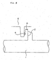
- One example of the prior art to measure the axial elongation of a rotary shaft with such an object is to use a gap sensor to detect a gap caused by the axial elongation, as shown in Fig. 5.
- numeral 1 designates a rotary shaft and this rotary shaft 1 is provided with a target face 2 for measuring the axial elongation.
- a gap sensor 4 is arranged so as to oppose the target face 2.
- the gap sensor 4 is fitted to a stationary part 6.
- the gap sensor 4 measures a gap 8 between the target face 2 and the sensor 4 and, by the change of this gap 8, the axial elongation of the rotary shaft 1 is measured.
- the elongation of the rotary shaft 1 is directly measured by the gap sensor 4 relative to the stationary part 6. Therefore, in case the axial elongation of the rotary shaft 1 is large, it is necessary to measure the gap 8 over a wide range, but to measure the gap 8 by the gap sensor 4 over the wide range often results in the less accuracy.
- the gap sensor 4 is provided in the axial directional space around the rotary shaft 1 where the gap 8 to be measured exists, a certain space is required in the axial direction of the rotary shaft 1 for installing the gap sensor 4.
- DE 39 08 248 A discloses a method and device for measuring an axial elongation of a rotary shaft in which a first mark is provided at the outer peripheral surface of the rotary shaft so as to extend parallel to the rotational axis and a second mark is arranged in an inclined angle thereto.
- a sensor is provided opposed to the surface of the rotary shaft so as to detect the passing of the marks upon rotation of the shaft.
- the detection signals are used as start and stop signals for a time measuring device in order to detect the interval between the signals representing the passing of the first and second marks.
- a ratio of the interval between two consecutive detections of the same mark and the interval between the detections of consecutive marks are used.
- JP 63313007 A discloses another method and device for measuring the axial elongation of a rotary shaft in which similar marks are used on the outer peripheral surface of the rotary shaft.
- two sensors are provided to respectively detect the passing of one of the marks and the elongation quantity of the shaft is calculated from the time difference from a measurement time interval determined by the signal from the sensor sensing the reference mark extending in the axial direction and the measurement time interval determined by the signal from the second sensor sensing the inclined mark.
- the present invention provides a rotary shaft axial elongation measuring method for measuring an axial elongation of a rotary shaft as defined in claim 1 and a corresponding measuring device as defined in claim 2.
- the circumferential directional position of the measuring mark line relative to the position of the reference mark line changes according to the axial directional position thereof.
- the sensor generates the pulses when the reference mark and the measuring mark pass by the sensor following the rotation of the rotary shaft and hence, if the axial directional position of the rotary shaft opposing the sensor changes due to the axial elongation of the rotary shaft, then the interval of the pulses generated by the sensor differs. Consequently, by measuring the change in the interval of the pulses generated by the sensor, the axial elongation of the rotary shaft can be measured.
- the steps are simplified such that the reference mark, and the measuring mark arranged inclinedly relative to the axial direction of the rotary shaft, are provided on the rotational surface of the rotary shaft, the axial elongation of which is to be measured, and the sensor is arranged fixedly so as to oppose the rotational surface of the rotary shaft for generating pulses upon passing by of the mentioned marks following the rotation of the rotary shaft.
- the gap between the sensor and the rotational surface of the rotary shaft opposing the sensor does not change substantially by the axial elongation of the rotary shaft and the accuracy of measuring the axial elongation by the sensor is in no case reduced by the sizes of the axial elongation.
- such a device is provided as is able to measure the axial elongation of the rotary shaft based on the axial elongation measuring method of the present invention as mentioned above.
- the gap between the sensor and the rotational surface is constant regardless of sizes of the axial elongation of the rotary shaft and measuring of the axial elongation with a high accuracy can be performed.
- the axial elongation measuring device of the present invention as the sensor may be arranged with a predetermined gap being maintained between itself and the rotational surface of the rotary shaft, only a narrow space is required for measuring the axial elongation regardless of sizes of the axial elongation.
- the reference mark and the measuring mark provided on the rotational surface of the rotary shaft in the axial elongation measuring device of the present invention may be two marks provided such that an interval between them in the circumferential direction of the rotary shaft differs according to the axial directional position of the rotary shaft. These two marks may be two grooves or two wire members both provided in a turned V shape.
- the measuring mark used in the axial elongation measuring device of the present invention may be a groove or a wire member both provided in a spiral shape on the rotational surface of the rotary shaft.
- the axial elongation measuring device of the present invention may be of a simple construction that is made easily and less costly.
- the sensor used in the axial elongation measuring method and device of the present invention may be an ordinary gap sensor, such as a capacitance type gap sensor or eddy current gap sensor, or may be a photoelectric sensor that generates a pulse signal upon passing of a mark provided on the rotational surface.
- the measuring device that can be easily installed for enabling the measuring of the axial elongation is provided.
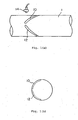
- numerals 10 and 12 designate grooves, that are provided in a rotational outer circumferential surface of a rotary shaft 1 so as to oppose one another inclinedly in a turned V shape.
- the grooves 10, 12, opposing one another extend inclinedly in an axial direction of the rotary shaft 1 and an interval between the grooves 10, 12 changes according to the axial directional position thereof, so that a construction is made such that one of the grooves 10, 12 constitutes a reference mark as hereinafter referred to and the other constitutes a measuring mark as hereinafter referred to.
- Numeral 14 designates a sensor, that is arranged so as to oppose the rotational outer circumferential surface of the rotary shaft 1.
- This sensor 14 may be a sensor, such as a capacitance type gap sensor, eddy current gap sensor or photoelectric sensor, that generates a pulse or pulse signal according to a change in a capacitance, eddy current or reflection of light following a change in a gap between the sensor 14 and the rotational outer circumferential surface of the rotary shaft 1 when the grooves 10, 12 pass by the sensor 14 by the rotation of the rotary shaft 1.
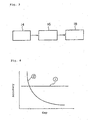
- Fig. 3 is a block diagram showing an entire construction of the axial elongation measuring device, wherein the pulse interval ratio of the pulses detected by the sensor 14 is sent to a data processing part 16 and the axial elongation obtained at the data processing part 16 is displayed at a display part 18.
- the grooves 10, 12 of the rotary shaft 1 may be provided in the outer circumferential surface of the rotary shaft 1 within the range of 1/2 or less of the entire outer circumference as shown in Fig. 1(b) and then, if the ratio t1/t2 is more than 0.5 (t1/t2>0.5), the axial elongation and the ratio t1/t2 can be decided correspondingly as (1-t1/t2) and thereby the data processing can be simplified.
- Fig. 4 shows the accuracy of the present invention and 2 shows the state where the measuring accuracy becomes lower as the gap between the sensor and the object to be measured becomes larger by the axial elongation as in the case shown in Fig. 5.
- a wire member such as a wire made of aluminum or stainless steel, may be fitted instead as a mark by spot welding or the like so as to form a projection on the rotational surface.
Landscapes
- Physics & Mathematics (AREA)
- General Physics & Mathematics (AREA)
- Measurement Of Length, Angles, Or The Like Using Electric Or Magnetic Means (AREA)
- Length Measuring Devices With Unspecified Measuring Means (AREA)
- Length Measuring Devices By Optical Means (AREA)
Description
- The present invention relates to a rotary shaft axial elongation measuring method and a device therefor, such as for a gas turbine or steam turbine rotor shaft, that elongates in the axial direction.
- As a rotor shaft of a gas turbine or steam turbine causes an axial elongation according to temperature change, it is necessary to accurately monitor whether the elongation is within a predetermined range or not so that no mutual contact of a moving blade and a stationary blade may be caused. One example of the prior art to measure the axial elongation of a rotary shaft with such an object is to use a gap sensor to detect a gap caused by the axial elongation, as shown in Fig. 5.
- In Fig. 5, numeral 1 designates a rotary shaft and this rotary shaft 1 is provided with a
target face 2 for measuring the axial elongation. Agap sensor 4 is arranged so as to oppose thetarget face 2. Thegap sensor 4 is fitted to astationary part 6. Thegap sensor 4 measures agap 8 between thetarget face 2 and thesensor 4 and, by the change of thisgap 8, the axial elongation of the rotary shaft 1 is measured. - In the prior art axial elongation measuring device as mentioned above, the elongation of the rotary shaft 1 is directly measured by the
gap sensor 4 relative to thestationary part 6. Therefore, in case the axial elongation of the rotary shaft 1 is large, it is necessary to measure thegap 8 over a wide range, but to measure thegap 8 by thegap sensor 4 over the wide range often results in the less accuracy. - Also, as the
gap sensor 4 is provided in the axial directional space around the rotary shaft 1 where thegap 8 to be measured exists, a certain space is required in the axial direction of the rotary shaft 1 for installing thegap sensor 4. - DE 39 08 248 A discloses a method and device for measuring an axial elongation of a rotary shaft in which a first mark is provided at the outer peripheral surface of the rotary shaft so as to extend parallel to the rotational axis and a second mark is arranged in an inclined angle thereto. A sensor is provided opposed to the surface of the rotary shaft so as to detect the passing of the marks upon rotation of the shaft. The detection signals are used as start and stop signals for a time measuring device in order to detect the interval between the signals representing the passing of the first and second marks. In order to determine the axial elongation of the shaft a ratio of the interval between two consecutive detections of the same mark and the interval between the detections of consecutive marks are used.
- JP 63313007 A (Abstract) discloses another method and device for measuring the axial elongation of a rotary shaft in which similar marks are used on the outer peripheral surface of the rotary shaft. In addition, two sensors are provided to respectively detect the passing of one of the marks and the elongation quantity of the shaft is calculated from the time difference from a measurement time interval determined by the signal from the sensor sensing the reference mark extending in the axial direction and the measurement time interval determined by the signal from the second sensor sensing the inclined mark.
- In view of the mentioned problems in the prior art rotary shaft axial elongation measuring device, it is an object of the present invention to provide a rotary shaft axial elongation measuring method and a device therefor that are free from such problems as mentioned above and are able to measure an axial elongation of a rotary shaft with a high accuracy regardless of sizes of the axial elongation.
- As a rotary shaft axial elongation measuring method for solving the mentioned problems, the present invention provides a rotary shaft axial elongation measuring method for measuring an axial elongation of a rotary shaft as defined in claim 1 and a corresponding measuring device as defined in
claim 2. - According to the axial elongation measuring method of the present invention, as the reference and measuring marks are provided inclinedly relative to the axial direction of the rotary shaft, the circumferential directional position of the measuring mark line relative to the position of the reference mark line changes according to the axial directional position thereof. On the other hand, the sensor generates the pulses when the reference mark and the measuring mark pass by the sensor following the rotation of the rotary shaft and hence, if the axial directional position of the rotary shaft opposing the sensor changes due to the axial elongation of the rotary shaft, then the interval of the pulses generated by the sensor differs. Consequently, by measuring the change in the interval of the pulses generated by the sensor, the axial elongation of the rotary shaft can be measured.
- In the mentioned axial elongation measuring method of the present invention, the steps are simplified such that the reference mark, and the measuring mark arranged inclinedly relative to the axial direction of the rotary shaft, are provided on the rotational surface of the rotary shaft, the axial elongation of which is to be measured, and the sensor is arranged fixedly so as to oppose the rotational surface of the rotary shaft for generating pulses upon passing by of the mentioned marks following the rotation of the rotary shaft. Hence, the gap between the sensor and the rotational surface of the rotary shaft opposing the sensor does not change substantially by the axial elongation of the rotary shaft and the accuracy of measuring the axial elongation by the sensor is in no case reduced by the sizes of the axial elongation. Also, according to the method of the present invention, there is no need to install such a sensor and a target face as in the prior art case in the axial directional space around the rotary shaft and thus there occurs no case where the measuring becomes impossible due to a limitation in the axial directional space of the rotary shaft.
- According to the rotary shaft axial elongation measuring device of the present invention, such a device is provided as is able to measure the axial elongation of the rotary shaft based on the axial elongation measuring method of the present invention as mentioned above.
- In the axial elongation measuring device of the present invention, as the construction is made such that the axial elongation data is obtained by the sensor arranged fixedly so as to oppose the rotational surface of the rotary shaft, the gap between the sensor and the rotational surface is constant regardless of sizes of the axial elongation of the rotary shaft and measuring of the axial elongation with a high accuracy can be performed.
- Also, in the axial elongation measuring device of the present invention, as the sensor may be arranged with a predetermined gap being maintained between itself and the rotational surface of the rotary shaft, only a narrow space is required for measuring the axial elongation regardless of sizes of the axial elongation.
- The reference mark and the measuring mark provided on the rotational surface of the rotary shaft in the axial elongation measuring device of the present invention may be two marks provided such that an interval between them in the circumferential direction of the rotary shaft differs according to the axial directional position of the rotary shaft. These two marks may be two grooves or two wire members both provided in a turned V shape.
- Also, the measuring mark used in the axial elongation measuring device of the present invention may be a groove or a wire member both provided in a spiral shape on the rotational surface of the rotary shaft.
- As mentioned above, the axial elongation measuring device of the present invention may be of a simple construction that is made easily and less costly.
- The sensor used in the axial elongation measuring method and device of the present invention may be an ordinary gap sensor, such as a capacitance type gap sensor or eddy current gap sensor, or may be a photoelectric sensor that generates a pulse signal upon passing of a mark provided on the rotational surface.
- According to the present invention as described above, even in the case where the rotary shaft affords no space for measuring by the conventional art to thereby make the measuring of the axial elongation impossible, the measuring device that can be easily installed for enabling the measuring of the axial elongation is provided.
-
- Figs. 1(a) and 1(b) show a rotary shaft used in an embodiment according to the present invention, wherein Fig. 1(a) is a side view and Fig. 1(b) is a front view.
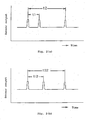
- Figs. 2(a) and 2(b) are explanatory views showing the state where pulses generated by a sensor upon rotation of the rotary shaft of Figs. 1(a) and 1(b) change from Fig. 2(a) to Fig. 2(b) by an axial elongation.
- Fig. 3 is a block diagram showing an entire construction of an axial elongation measuring device of the embodiment according to the present invention.
- Fig. 4 is an explanatory view showing the relation between an accuracy of the axial elongation measuring by the present invention and that by the prior art.
- Fig. 5 is a side view showing a construction of a prior art axial elongation measuring device.
- Herebelow, a rotary shaft axial elongation measuring device of the present invention will be concretely described based on an embodiment as illustrated.
- An embodiment according to the present invention will be described with reference to Figs. 1 to 4. In Figs. 1(a) and 1(b),
numerals grooves grooves grooves - Numeral 14 designates a sensor, that is arranged so as to oppose the rotational outer circumferential surface of the rotary shaft 1. This
sensor 14 may be a sensor, such as a capacitance type gap sensor, eddy current gap sensor or photoelectric sensor, that generates a pulse or pulse signal according to a change in a capacitance, eddy current or reflection of light following a change in a gap between thesensor 14 and the rotational outer circumferential surface of the rotary shaft 1 when thegrooves sensor 14 by the rotation of the rotary shaft 1. - In the measuring device of Figs. 1(a) and 1(b) constructed as above, if the rotary shaft 1 rotates, the
grooves sensor 14 and thesensor 14 puts out pulses, as shown in Figs. 2(a) and 2(b), corresponding to time t1 that is a time from passing by thesensor 14 of thegroove 10 to that of thegroove 12 and time t2 that is a time of one rotation of the rotary shaft 1. - As the position of the
sensor 14 is fixed, if the rotary shaft 1 elongates in the axial direction and the axial directional position of thegrooves grooves sensor 14 changes. Hence, by the axial elongation of the rotary shaft 1, the pulses generated by thesensor 14 change as shown in Fig. 2(b), so that the pulses change from those having a pulse interval ratio of t1/t2 in Fig. 2(a) to those having a different pulse interval ratio of t12/t22 in Fig. 2(b). - Thus, by measuring the change in the pulse interval ratio t1/t2 obtained by the
sensor 14, the axial elongation of the rotary shaft 1 can be measured. - Fig. 3 is a block diagram showing an entire construction of the axial elongation measuring device, wherein the pulse interval ratio of the pulses detected by the
sensor 14 is sent to adata processing part 16 and the axial elongation obtained at thedata processing part 16 is displayed at adisplay part 18. - The
grooves - According to the means to measure the interval changes of the marks provided in the rotational outer circumferential surface of the rotary shaft 1 by the
sensor 14 arranged oppositely to this rotational surface as described above, as the gap between thesensor 14 and the rotational surface as the object to be measured is constant regardless of the axial elongation, the measuring accuracy can be maintained constant. This is shown by Fig. 4, wherein ① shows the accuracy of the present invention and ② shows the state where the measuring accuracy becomes lower as the gap between the sensor and the object to be measured becomes larger by the axial elongation as in the case shown in Fig. 5. - It is to be noted that, while the present invention has been concretely described based on the embodiment as illustrated, the present invention is not limited to this embodiment but, needless to mention, may be added with various modifications in the concrete structure and construction thereof as come within the scope of the claims as appended.
- For example, while in the above embodiment, the grooves are formed as the reference mark and the measuring mark provided on the rotational surface of the rotary shaft 1, a wire member, such as a wire made of aluminum or stainless steel, may be fitted instead as a mark by spot welding or the like so as to form a projection on the rotational surface.
Claims (5)
- A rotary shaft axial elongation measuring method for measuring an axial elongation of a rotary shaft, comprising the steps of:providing a reference mark (10) and a measuring mark (12) on a rotational surface of said rotary shaft (1) such that said reference mark (10) and said measuring mark (12) oppose each other, extend inclinedly in an axial direction of said rotary shaft (1), and such that an interval between said marks (10,12) changes according to the axial directional position thereof;arranging a sensor (14) fixedly so as to oppose the rotational surface of said rotary shaft (1), said sensor (14) generating pulses upon passing of said marks (10,12) following a rotation of said rotary shaft (1); andmeasuring the axial elongation of said rotary shaft (1) from a change in ratio between an interval (t1, t12) of the pulses generated by said sensor (14) upon passing of said reference mark (10) and measuring mark (10) and an interval (t2,t22) of the pulses representing one rotation of the rotary shaft (1).
- A rotary shaft axial elongation measuring device for measuring an axial elongation of a rotary shaft, comprising:said shaft (1) having a reference mark (10) and a measuring mark (12) provided on a rotational surface of said rotary shaft (1), said reference mark (10) and said measuring mark (12) being arranged such that said reference mark (10) and said measuring mark (12) oppose each other, extend inclinedly in an axial direction of said rotary shaft (1)and such that an interval between said marks (10,12) changes according to the axial directional position thereof;a sensor (14) arranged fixedly so as to oppose the rotational surface of said rotary shaft (1), said sensor (14) generating pulses upon passing of said marks (10,12) following a rotation of said rotary shaft (1); anda data processing part (16) arranged for measuring the axial elongation of said rotary shaft (1) from a change in ratio between an interval (t1, t12) of the pulses generated by said sensor (14) upon passing of said reference mark (10) and measuring mark (10) and an interval (t2,t22) of the pulses representing one rotation of the rotary shaft (1).
- A rotary shaft axial elongation measuring device as claimed in claim 2, wherein said two marks are two grooves (10,12).
- A rotary shaft axial elongation measuring device as claimed in claim 2, wherein said two marks are two wire members.
- A rotary shaft axial elongation measuring device as claimed in anyone of claims 2 to 4, wherein said sensor (14) is anyone of a capacitance type gap sensor, an eddy current gap sensor and a photoelectric sensor.
Applications Claiming Priority (2)
| Application Number | Priority Date | Filing Date | Title |
|---|---|---|---|
| JP2000281826 | 2000-09-18 | ||
| JP2000281826A JP2002090138A (en) | 2000-09-18 | 2000-09-18 | Measuring method and measuring device for axial elongation of rotating shaft |
Publications (2)
| Publication Number | Publication Date |
|---|---|
| EP1189015A1 EP1189015A1 (en) | 2002-03-20 |
| EP1189015B1 true EP1189015B1 (en) | 2006-10-18 |
Family
ID=18766428
Family Applications (1)
| Application Number | Title | Priority Date | Filing Date |
|---|---|---|---|
| EP01119223A Expired - Lifetime EP1189015B1 (en) | 2000-09-18 | 2001-08-09 | Rotary shaft axial elongation measuring method and device |
Country Status (5)
| Country | Link |
|---|---|
| US (1) | US6807870B2 (en) |
| EP (1) | EP1189015B1 (en) |
| JP (1) | JP2002090138A (en) |
| CA (1) | CA2355496C (en) |
| DE (1) | DE60123899D1 (en) |
Families Citing this family (16)
| Publication number | Priority date | Publication date | Assignee | Title |
|---|---|---|---|---|
| US7121012B2 (en) * | 1999-12-14 | 2006-10-17 | Voecks Larry A | Apparatus and method for measuring and controlling pendulum motion |
| US7845087B2 (en) * | 1999-12-14 | 2010-12-07 | Voecks Larry A | Apparatus and method for measuring and controlling pendulum motion |
| DE102006059439B4 (en) * | 2006-12-15 | 2018-01-25 | Prüftechnik Dieter Busch AG | Method and device for dynamically measuring the axial deformation of a rotating hollow shaft |
| WO2009048970A1 (en) * | 2007-10-09 | 2009-04-16 | Schweitzer Engineering Laboratories, Inc. | Power angle monitor |
| US8042412B2 (en) * | 2008-06-25 | 2011-10-25 | General Electric Company | Turbomachinery system fiberoptic multi-parameter sensing system and method |
| FR2994262B1 (en) * | 2012-08-02 | 2014-08-29 | Turbomeca | MEASURING FLOWING OF A TURBINE BLADE |
| US8912792B2 (en) | 2012-08-24 | 2014-12-16 | Schweitzer Engineering Laboratories, Inc. | Systems and methods for rotor angle measurement in an electrical generator |
| WO2014134129A1 (en) | 2013-02-26 | 2014-09-04 | Fuller Kenneth A | Methods and apparatus for measuring axial shaft displacement within gas turbine engines |
| DE102014205291A1 (en) * | 2014-03-21 | 2015-09-24 | Siemens Aktiengesellschaft | A method for determining the axial position of the sensor head of a magnetoelastic sensor with respect to a rotating shaft |
| US10317467B2 (en) | 2014-05-19 | 2019-06-11 | Schweitzer Engineering Laboratories, Inc. | Synchronous machine monitoring and determination of a loss-of-field event using time stamped electrical and mechanical data |
| US10063124B2 (en) | 2015-12-10 | 2018-08-28 | Schweitzer Engineering Laboratories, Inc. | Shaft mounted monitor for rotating machinery |
| US9835440B2 (en) | 2015-12-17 | 2017-12-05 | General Electric Company | Methods for monitoring turbine components |
| US10024760B2 (en) | 2015-12-17 | 2018-07-17 | General Electric Company | Methods for monitoring turbine components |
| US9800055B2 (en) | 2016-01-21 | 2017-10-24 | Schweitzer Engineering Laboratories, Inc. | Synchronization of generators using a common time reference |
| US10523150B2 (en) | 2016-09-15 | 2019-12-31 | Schweitzer Engineering Laboratories, Inc. | Systems and methods for motor slip calculation using shaft-mounted sensors |
| CN113154016B (en) * | 2020-01-07 | 2022-10-14 | 黄国轩 | Cooling system of shaft rotating equipment |
Family Cites Families (13)
| Publication number | Priority date | Publication date | Assignee | Title |
|---|---|---|---|---|
| US4112746A (en) * | 1976-04-02 | 1978-09-12 | The Yokohama Rubber Co., Ltd. | Opto-electronic tensile testing system |
| US4166383A (en) * | 1978-03-20 | 1979-09-04 | The Laitram Corporation | Optical shaft torque meter |
| JPS5913906A (en) * | 1982-07-14 | 1984-01-24 | Mitsui Toatsu Chem Inc | Measuring device of direction and displacement of rotating body in rotating shaft direction |
| US4712432A (en) * | 1984-11-30 | 1987-12-15 | Al Sin Seiki Kabushiki Kaisha | Torque sensor |
| JPS61181904A (en) * | 1985-02-08 | 1986-08-14 | Hitachi Ltd | Measuring or monitoring axial displacement of rotating body without contacting |
| JPH0697161B2 (en) * | 1985-08-23 | 1994-11-30 | 株式会社エスジ− | Absolute linear position detector |
| JPS63313007A (en) * | 1987-06-16 | 1988-12-21 | Natl Aerospace Lab | Measuring instrument for axial elongation quantity of rotary body |
| DE3908248A1 (en) * | 1989-03-14 | 1990-09-20 | Schenck Ag Carl | Method and device for measuring axial displacements between a rotatable or rotating body and a component arranged in a rotationally fixed fashion relative to the body |
| US5201964A (en) * | 1989-06-21 | 1993-04-13 | The United States Of America As Represented By The Secretary Of The Navy | Magnetostrictive torque sensor |
| JPH05133201A (en) | 1991-11-07 | 1993-05-28 | Mitsubishi Heavy Ind Ltd | Expansion difference adjustor for rotary machine |
| TW227601B (en) * | 1993-01-25 | 1994-08-01 | Gen Electric | |
| US5723794A (en) * | 1995-09-29 | 1998-03-03 | Reliance Electric Industrial Company | Photoelastic neural torque sensor |
| DE19609320A1 (en) * | 1996-03-09 | 1997-09-11 | Norbert Guenther | Method and system of measuring rotary torque and axial push of rotating shafts of machines and installations |
-
2000
- 2000-09-18 JP JP2000281826A patent/JP2002090138A/en active Pending
-
2001
- 2001-08-09 EP EP01119223A patent/EP1189015B1/en not_active Expired - Lifetime
- 2001-08-09 DE DE60123899T patent/DE60123899D1/en not_active Expired - Lifetime
- 2001-08-14 US US09/928,449 patent/US6807870B2/en not_active Expired - Lifetime
- 2001-08-17 CA CA002355496A patent/CA2355496C/en not_active Expired - Fee Related
Also Published As
| Publication number | Publication date |
|---|---|
| DE60123899D1 (en) | 2006-11-30 |
| JP2002090138A (en) | 2002-03-27 |
| EP1189015A1 (en) | 2002-03-20 |
| US6807870B2 (en) | 2004-10-26 |
| CA2355496C (en) | 2006-05-30 |
| CA2355496A1 (en) | 2002-03-18 |
| US20020033052A1 (en) | 2002-03-21 |
Similar Documents
| Publication | Publication Date | Title |
|---|---|---|
| EP1189015B1 (en) | Rotary shaft axial elongation measuring method and device | |
| US4876505A (en) | Apparatus and method for monitoring steam turbine shroud clearance | |
| US8687206B2 (en) | Optical detection of airfoil axial position with NSMS | |
| US6732713B1 (en) | Crank angle detection apparatus | |
| JP4667186B2 (en) | Rotational accuracy measurement method | |
| US6782766B2 (en) | Apparatus for detecting torque, axial position and axial alignment of a rotating shaft | |
| US9823145B2 (en) | Bearing nut for measuring the rotational speed of a shaft connected to a turbomachine and associated measuring device | |
| CN111380468A (en) | Device and method for measuring rotor eccentricity and phase of steam turbine generator unit | |
| WO2009157436A1 (en) | Device and method of monitoring sliding conditions of piston ring | |
| JP2000321122A (en) | Vibration measuring apparatus for rotor blade | |
| US10627256B2 (en) | Rotation angle detecting device | |
| CN109282927B (en) | Shaft torque measurement system and measurement method | |
| CN110672059B (en) | Calibrating device and calibrating method for slide micrometer | |
| CN212109904U (en) | Turbine generator set rotor eccentricity and phase measuring device thereof | |
| JPH1151608A (en) | Angular position detector | |
| US20220128096A1 (en) | Rolling bearing assembly | |
| JP2009041704A (en) | Rolling bearing device | |
| JPS59123615A (en) | System for detecting abnormality of rotating cutter in early stage | |
| CN113464377B (en) | Impeller detection system and method of wind generating set | |
| JPS61124815A (en) | Clearance measuring device | |
| CN216695033U (en) | Wind vane type zero error measuring system and measuring tool for angle of attack sensor | |
| JP2585953B2 (en) | Open blade thickness monitor for rotating machinery | |
| JPH10252749A (en) | Rolling bearing device | |
| US20160319695A1 (en) | System and methods for determining blade clearance for asymmertic rotors | |
| JP2877474B2 (en) | Scanning temperature monitor |
Legal Events
| Date | Code | Title | Description |
|---|---|---|---|
| PUAI | Public reference made under article 153(3) epc to a published international application that has entered the european phase |
Free format text: ORIGINAL CODE: 0009012 |
|
| 17P | Request for examination filed |
Effective date: 20010809 |
|
| AK | Designated contracting states |
Kind code of ref document: A1 Designated state(s): AT BE CH CY DE DK ES FI FR GB GR IE IT LI LU MC NL PT SE TR Kind code of ref document: A1 Designated state(s): CH DE FR GB IT LI |
|
| AX | Request for extension of the european patent |
Free format text: AL;LT;LV;MK;RO;SI |
|
| AKX | Designation fees paid |
Free format text: CH DE FR GB IT LI |
|
| 17Q | First examination report despatched |
Effective date: 20040513 |
|
| GRAP | Despatch of communication of intention to grant a patent |
Free format text: ORIGINAL CODE: EPIDOSNIGR1 |
|
| GRAS | Grant fee paid |
Free format text: ORIGINAL CODE: EPIDOSNIGR3 |
|
| GRAA | (expected) grant |
Free format text: ORIGINAL CODE: 0009210 |
|
| AK | Designated contracting states |
Kind code of ref document: B1 Designated state(s): CH DE FR GB IT LI |
|
| PG25 | Lapsed in a contracting state [announced via postgrant information from national office to epo] |
Ref country code: CH Free format text: LAPSE BECAUSE OF FAILURE TO SUBMIT A TRANSLATION OF THE DESCRIPTION OR TO PAY THE FEE WITHIN THE PRESCRIBED TIME-LIMIT Effective date: 20061018 Ref country code: LI Free format text: LAPSE BECAUSE OF FAILURE TO SUBMIT A TRANSLATION OF THE DESCRIPTION OR TO PAY THE FEE WITHIN THE PRESCRIBED TIME-LIMIT Effective date: 20061018 |
|
| REG | Reference to a national code |
Ref country code: GB Ref legal event code: FG4D |
|
| REG | Reference to a national code |
Ref country code: CH Ref legal event code: EP |
|
| REF | Corresponds to: |
Ref document number: 60123899 Country of ref document: DE Date of ref document: 20061130 Kind code of ref document: P |
|
| PG25 | Lapsed in a contracting state [announced via postgrant information from national office to epo] |
Ref country code: DE Free format text: LAPSE BECAUSE OF FAILURE TO SUBMIT A TRANSLATION OF THE DESCRIPTION OR TO PAY THE FEE WITHIN THE PRESCRIBED TIME-LIMIT Effective date: 20070119 |
|
| REG | Reference to a national code |
Ref country code: CH Ref legal event code: PL |
|
| EN | Fr: translation not filed | ||
| PLBE | No opposition filed within time limit |
Free format text: ORIGINAL CODE: 0009261 |
|
| STAA | Information on the status of an ep patent application or granted ep patent |
Free format text: STATUS: NO OPPOSITION FILED WITHIN TIME LIMIT |
|
| 26N | No opposition filed |
Effective date: 20070719 |
|
| PG25 | Lapsed in a contracting state [announced via postgrant information from national office to epo] |
Ref country code: FR Free format text: LAPSE BECAUSE OF FAILURE TO SUBMIT A TRANSLATION OF THE DESCRIPTION OR TO PAY THE FEE WITHIN THE PRESCRIBED TIME-LIMIT Effective date: 20070601 |
|
| PG25 | Lapsed in a contracting state [announced via postgrant information from national office to epo] |
Ref country code: FR Free format text: LAPSE BECAUSE OF FAILURE TO SUBMIT A TRANSLATION OF THE DESCRIPTION OR TO PAY THE FEE WITHIN THE PRESCRIBED TIME-LIMIT Effective date: 20061018 |
|
| PGFP | Annual fee paid to national office [announced via postgrant information from national office to epo] |
Ref country code: GB Payment date: 20160803 Year of fee payment: 16 Ref country code: IT Payment date: 20160822 Year of fee payment: 16 |
|
| GBPC | Gb: european patent ceased through non-payment of renewal fee |
Effective date: 20170809 |
|
| PG25 | Lapsed in a contracting state [announced via postgrant information from national office to epo] |
Ref country code: GB Free format text: LAPSE BECAUSE OF NON-PAYMENT OF DUE FEES Effective date: 20170809 |
|
| PG25 | Lapsed in a contracting state [announced via postgrant information from national office to epo] |
Ref country code: IT Free format text: LAPSE BECAUSE OF NON-PAYMENT OF DUE FEES Effective date: 20170809 |