EP1188495A1 - Vorrichtung zum hydromechanischen Umformen von Platinen, sowie eine Verbindungseinrichtung für eine solche Vorrichtung - Google Patents
Vorrichtung zum hydromechanischen Umformen von Platinen, sowie eine Verbindungseinrichtung für eine solche Vorrichtung Download PDFInfo
- Publication number
- EP1188495A1 EP1188495A1 EP01121429A EP01121429A EP1188495A1 EP 1188495 A1 EP1188495 A1 EP 1188495A1 EP 01121429 A EP01121429 A EP 01121429A EP 01121429 A EP01121429 A EP 01121429A EP 1188495 A1 EP1188495 A1 EP 1188495A1
- Authority
- EP
- European Patent Office
- Prior art keywords
- active medium
- table part
- forming tool
- medium container
- bore
- Prior art date
- Legal status (The legal status is an assumption and is not a legal conclusion. Google has not performed a legal analysis and makes no representation as to the accuracy of the status listed.)
- Granted
Links
Images

Classifications
-
- B—PERFORMING OPERATIONS; TRANSPORTING
- B21—MECHANICAL METAL-WORKING WITHOUT ESSENTIALLY REMOVING MATERIAL; PUNCHING METAL
- B21D—WORKING OR PROCESSING OF SHEET METAL OR METAL TUBES, RODS OR PROFILES WITHOUT ESSENTIALLY REMOVING MATERIAL; PUNCHING METAL
- B21D22/00—Shaping without cutting, by stamping, spinning, or deep-drawing
- B21D22/20—Deep-drawing
- B21D22/205—Hydro-mechanical deep-drawing
Definitions
- the invention relates to a device for hydromechanical Forming of boards with a table part above which a forming tool containing an active medium container, is provided, the active medium container at least one Supply and / or discharge for one adjustable one Has pressurizable active medium.
- Such devices are known. With these is instead of a molding die in the lower tool, an active medium container with liquid active medium, for example one Emulsion or solution.
- an active medium container with liquid active medium for example one Emulsion or solution.
- the intended stamp forms between a hold-down device and a pull ring clamped liquid-tight Circuit board, i.e. the sheet to be formed, against that with pressure acted active medium.
- the active medium While the active medium initially is subjected to a relatively low pressure, is removed from the mold after sinking the die into the circuit board has an active medium pressure of e.g. 300 bar or more built up.
- the pressure build-up in the active medium container takes place regulated in or before the inlets and / or outlets of the Active medium container provided valves that the active medium convey from a storage container to the active medium container or derive from it.
- the invention is therefore based on the object of a device according to the preamble of claim 1 to further that the above disadvantage of poor accessibility to the device due to the possibly numerous supply and discharge hoses is fixed, which in particular also leads to a larger one Safety for people working on the device leads because there is a large number of pressure hoses must always be laid in such a way that no risk or no risk Danger to the bystanders by this occur can.
- the task is performed by a device according to the preamble of claim 1 solved in that the at least one feed line and / or derivation at least partially in the table part integrated and via a connection device with the Active medium container is connectable.
- the pressurized supply lines and / or derivatives can also advantageously in a such a direction away from the device that a danger to people working on the device can largely be avoided by this.
- At least one feed line and / or discharge line is preferred provided like a gang in the table part.
- Particularly preferred are several supply lines and / or within the table part Derivatives as aisles and / or as a passage from one or a plurality of supply lines and / or discharge lines through a corridor integrated.
- the device is advantageously an additional Pressure casing created by the table part, which also has this security aspect.
- the feed lines and / or discharge lines are preferably in mechanically incorporated the table part, in particular by Drilling, milling or another mechanical separation process.
- the feed lines and / or Subsequent derivations also in existing table parts be incorporated.
- the Pipes and / or drains poured into the table section his. This method is preferred when manufacturing new used by table parts of the device which the table parts are produced in the casting process.
- the Pouring the leads and / or leads, that is Providing voids in the table part during casting the table part advantageously allows any Diameter of feed lines and / or discharge lines, i.e. passages, getting produced. This is the mechanical Incorporation into an existing table part very much more complicated possible.
- the diameter and the other dimensions of the leads and / or leads is essentially by the material thickness of the table part and the required stability when pressurized is limited. It is also possible to use the integrated in the table part Inlets and / or outlets with different Provide diameters so that different flow rates achieved in the transmitted active medium can be. This can change during feeding and removal of active medium prove to be advantageous.
- the supply lines integrated in the table part are preferably and / or derivatives and / or the table part designed so in particular, they have dimensions such that it for the flow with an active medium under one low and / or high pressure are suitable.
- leads and / or leads different diameters are provided in the table part be, each for the application of low or high pressures are formed.
- When applied with a high pressure can then, for example, only which a supply and / or derivations are used and at Applying a low pressure to both or only the other supply lines and / or derivatives. Also this can increase security for the device working people are increased.
- a Part of the at least one supply line and / or discharge line the table part, especially between table cylinders, for Adjusting the height of the table part can be arranged.
- This Arrangement proves to be advantageous if between the table cylinders have enough space to hold the Lead and / or discharge lead through there.
- the table part is advantageous towards its thickness with a hole or provided with a through opening.
- a corridor that extends both in the longitudinal direction and also extends in the direction of the thickness of the table part, or in the transverse direction of the table part and in its thickness - less manufacturing effort is required. Indeed the allocations and / or derivations remain outside or below the table section as pressure hoses intended.
- the advantage of better accessibility of the device from the side also remains in this embodiment get advantageous.
- the table part and / or the Provide the active media container with the connection device Preferably the table part and / or the Provide the active media container with the connection device.
- the connecting device preferably contains one itself unilaterally tapered bore and at least partially tapered connector, the sealing are mergable.
- the tapered bore is particularly preferred in the table part and that Connector on the forming tool and / or the Active medium container and / or the tapered bore in the forming tool and / or the active medium container and the connector is provided on the table part.
- Through the interlocking bore, in particular via cone shapes and the connector becomes one particularly well by pressure actionable connection created. Moreover is a centering of the bore and connector this makes it easier.
- the bore preferably opens Outer surface of the table part.
- This can be a partially tapered connector in this hole intervention. Only an O-ring or is used for sealing the like inserted into the bore and the connector even in the forming tool or active medium container through a corresponding sealing ring, in particular an O-ring, sealed.
- the connector in the Forming tool or screwed into the active medium container become. This creates a back pressure-proof connection form created.
- the end portion of the through the table part through hole or the passage of the supply lines and / or derivatives preferably cylindrical in shape and in particular provided with a thread into which the connecting piece can be screwed in.
- the bottom area of the Forming tool or active medium container one after outside opening to the table part or through opening which is otherwise tapered.
- This one too Embodiment is preferably in the bore and in the mounting area of the connecting piece each have a sealing ring intended.
- the forming tool having the active medium container is preferred can be lowered precisely on the table part, in particular before a forming process that the at least one Bore and the at least one connector sealing mesh. It is particularly advantageous here if tapering towards the bore Connectors are provided as these can be self-centering or at least one Support centering.
- the centering of the forming tool and table part can also be by bolts and / or pins are supported, which is also used as a connector can be used.
- the active medium container is usually filled, controlled by a control device or regulated by a control device, the valves between the reservoir for active medium and active medium container opens.
- at least one sensor means can preferably be triggered an independent filling of the active medium container after lowering the forming tool on the table part and sealing engagement of holes and Connectors are provided.
- the sensor means will for example at the outer end of the connector like that Hole arranged and act on an inlet or Exhaust valve between the reservoir and Active medium container is arranged, especially in Area of the connecting device or Connector can be arranged.
- Sensor means prove to be advantageous if between each forming process the forming tool, containing the Active medium container from which the table part is separated, that is is lifted from this. Unless the forming tool just added once to the table part and not is lifted off after each forming process, is preferably a filling of the active medium container over conventional valves between the reservoir and the Supply lines and / or discharge lines to the active medium container intended.
- the connecting piece preferably has fastening devices for fastening in the table part and / or the forming tool and / or the active medium container and is in particular provided with a thread.
- Fastening devices can be screws, for example be provided, which the connector in the area of a provided collar or a flange plate with the Forming tool or active medium container or the table part connect.
- the connector preferably an external thread, by means of which it is in a corresponding hole or opening in the table part and / or the forming tool or active medium container is attached.
- This is particularly preferably at least one connecting piece controllable from the table part and / or the forming tool or controllably extendable and into at least one hole insertable, especially via an electrically operated thread and / or hydraulically, mechanically or pneumatically operated, especially after centering holes beforehand and connectors to each other.
- the forming tool is first placed on the support brought the table part and only then the connecting pieces inserted into the corresponding holes, which in particular on electrical, hydraulic, mechanical or pneumatic way can happen.
- the at least one is preferably in or under the table part provided supply line and / or derivation on the by the Connecting device pioneering end with a connector for connection to an active medium line and / or a control or regulating device for controlling or regulating the supplied and / or derived amount of active medium.
- the Connector can either be an external thread or an internal thread have on which a conventional pressure hose can be connected. Alternatively, a latch lock can also be used with a retractable cap to loosen the connection can be provided.
- the connector can both in a first supply line manufactured as a passage and / or Derivation inserted in the table part or connected to it be, as well as one by the thickness of the Walking part of the table, provided with a connecting piece Bore inserted in particular with the provision of an elbow become.
- a connecting piece Bore inserted in particular with the provision of an elbow become.
- connection device for Use in a device for hydromechanical Forming of blanks according to the preamble of claim 18
- the connecting device has at least one at least partially tapered connector that can be engaged in a bore tapering on one side and with a fastening device for fastening to the Active medium container and / or the forming tool and / or the Active medium supply and / or derivative is provided.
- the special advantage of the device is also that that the number of connections or supply lines and / or derivatives can be chosen arbitrarily. So for example several courses can be provided in the table part. There are also several holes in both the forming tool as well as in the table part. Even the arrangement of the individual Supply lines and / or discharge lines or from their connecting devices for connection to the active medium container or the forming tool can be selected as desired.
- the single ones Inlets and / or outlets in the form of aisles or holes within the table part can be shaped as desired be, especially a round, angular, square or polygonal or arbitrarily shaped cross section exhibit.
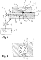
- Figure 1 shows a cross section of a first embodiment a table part 1 and a forming tool 2 with a Active medium container 3 for receiving an active medium 4 as Part of a device for hydromechanical forming of Boards 5.
- the board 5 is on the forming tool, which in the device is in particular a lower tool, so that an upper tool, not shown, with a Stamp reshaping the board against that in the active medium buildable pressure.
- This is the circuit board of hold-down devices, also not shown, on the Surface of the forming tool 2 held.
- the active medium 4 is the active medium container 3 by a Lead 6 supplied. This can also be used as a derivative be used to close the active medium container again Drain. Both for filling and for emptying the Active medium container is a reservoir 7 and a pump or a valve 8 is provided.
- the lines 6 comprise lines 9, which is outside the table part 1 between the storage container 7 and the pump / valve 8 and between Pump / valve 8 and the table part 1 are arranged.
- the lines 6 also include a feed / discharge line 10 which is inside the table part 1 is provided.
- the in the table part 1 provided supply / discharge line 10 is integrated in this way, either by a mechanical separation process, Drilling or milling, worked into the table part or already during the casting process of the table part Cavity is provided in this.
- the inlet / outlet 10 is made in the longitudinal direction of the Table part 1 extending portion 11 and from one perpendicular to it, i.e. essentially in the direction of the Thickness of the table part 1 extending part 12 is built.
- the second part 12 is via a connecting device 13 connected to the active medium container, the Connection device a connector 14 and a bore in the forming tool 2 comprises.
- the supply / discharge line 10 for the active medium 4 can between the active medium container 3 and the storage container 7 are pumped back and forth or in the active medium container put yourself under the necessary pressure. This is also preferably done via the valve outlined or the pump 8 and a regulating device for regulating the pressure required for hydromechanical forming in the active medium.
- the supply / discharge lines 10th also be provided below the table part 1 so that only the first part 11 led below the table part becomes, whereas the second part 12 continues to cross extends through the table part 1.
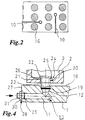
- Figure 2 in a cross-sectional view, wherein the cross section transverse to the table part 1 moving Table cylinders 16 is pulled.
- the supply / discharge lines 10 are in two different directions between the table cylinders arranged to adjust the height of the table part. It can also in any other direction and other Position and elsewhere a respective feed / discharge for the active medium between the table cylinders 16 be performed.
- FIG. 3 The cross section sketched in FIG. 3 through the table part 1, which is taken along the line A-A according to FIG. 1, as shown there, a feed / discharge 10.
- the active medium becomes the embodiment according to FIG. 1 not led directly through this inlet / outlet 10, but by additional supply / discharge lines 17 arranged therein.
- the supply / discharge lines 17 are preferably formed as hoses. Alternatively, you can also replace the one course or a feed / discharge line 10 with those provided therein Hoses several supply / discharge lines 17 directly into the table part 1 formed by drilling or pouring cavities his.
- the number of individual supply / discharge lines 17 is included any and should depend on the material thickness of the table part 1 as well as the required amount of active medium to be pumped back and forth and the pressure acting in the active medium be made.
- Figures 4 and 5 show different embodiments of connecting devices 13 for connecting the supply / discharge lines 10 or supply / discharge lines 17 with the active medium container 3.
- Connection device 13 is a feed / discharge in the table part 1 17 integrated.
- the second part 12 of the Inlet / outlet 10 is a tapered bore executed, the bore to the surface 18 of the Cantilevered part of the table.
- a sealing ring 19 is arranged in the hole or the second Part 12 arranged. This is preferred an o-ring.
- a connector 20 as a connector for connecting to the second part 12 of the feed / discharge 10 inserted.
- the connector has a cylindrical part 21, a flange part 22 and a conical part 23.
- the conical part 23 engages in the second part 12 of the Inlet / outlet 10, the conical part 23 in essential from the dimensions and shape Shapes and dimensions of the second part 12 of the inlet / outlet 10 corresponds.
- the connector 20 is here on the part of the active medium container by means of Flange part 22 on its inner surface 24 via a additional sealing ring 25 sealed.
- the cylindrical part 21 of the connector 20 is with provided with an external thread 26, whereas the bore 15 is provided with an internal thread, so that the connecting piece 20 can be screwed into the bore. This takes place from the direction of the active medium container, i.e. the away from the table part 1 side of the forming tool.
- a connector 28 For connecting the supply / discharge line 10 to the external line 9 for connection to the pump / valve 8 is at one end 27 of the table part 1, a connector 28 is provided.
- the connector consists of one in the first part 11 the inlet / outlet 10 inserted, in particular screwed, Section 29, a flange 30 and one with a External thread provided connecting part 31.
- the connecting part 31 an internal thread can also be used to connect the line 9 have, as in the embodiment according to FIG. 5 is shown.
- the feed / discharge is 10 according to the embodiment of Figure 2 in part led under the table part 1 along. Only the second Part 12 is a bore through the table part 1 educated.
- a connector 32 is the Connection device for connecting supply / discharge and Active medium container inserted.
- the connector is for this purpose with a cylindrical section 33 and a Provided flange part 34.
- the cylindrical section 33 is screwed into the second part 12. It partly sticks out beyond the underside of the table part 1, being on this End of the cylindrical section 33, a connector 39 for connection to an external line 9 can be added.
- the connector 39 is formed as an elbow to the Active medium line at least initially essentially in parallel to be able to arrange to the table part.
- the flange part 34 is via a sealing ring 35 and fastening devices 36 in the area of the top 18 of the table part arranged embedded in this.
- the fasteners are only hinted at here. You are special executed in the form of screws.
- On the flange part 34 is followed by a conical section 37.
- the conical section 37 can, just like the conical Part 23 of the connector 20, with an external thread be provided with a corresponding internal thread a hole can interact.
- the bore 15 in the forming tool can for this purpose like the second Part of the supply / discharge line 10 according to FIG. 4 with an internal thread be provided.
- a sealing ring 38 is additionally inserted into the bore 15.
- the pitch of the thread of the conical sections or Parts or holes is preferably chosen so that a good centering of the bore and connector to each other is possible and on the other hand an adequate one Stability and a sufficient flow cross section for the active medium is retained.
- the connectors in particular the connector according to Figure 4, on its cylindrical Part as well as the thread over which they fit into the respective Hole are inserted, adjusted, which makes it possible is that in particular the conical part of the Only then connectors over the surface of the Table part or the forming tool is extended when this actually above the corresponding hole, in that it should intervene in. For this you can Sensor means are provided which extend the Only start connecting pieces at this moment.
- connection device with the active medium container is connectable.
- connecting devices can for example, appropriately trained pipes be provided if the forming tool and the table part are not must be differentiated from each other.
Landscapes
- Engineering & Computer Science (AREA)
- Mechanical Engineering (AREA)
- Filling Or Discharging Of Gas Storage Vessels (AREA)
- Containers And Packaging Bodies Having A Special Means To Remove Contents (AREA)
Abstract
Description
- Figur 1
- eine Prinzipskizze einer erfindungsgemäßen Vorrichtung in Form von Gängen als in einem Tischteil integrierter Zuleitung,
- Figur 2
- eine Draufsicht auf eine zweite Ausführungsform einer erfindungsgemäßen Vorrichtung, bei der Zuleitungen bzw. Ableitungen zwischen Tischzylindern unterhalb des Tischteils angeordnet sind,
- Figur 3
- eine Querschnittsansicht durch das Tischteil gemäß Figur 1 mit in einem Gang angeordneten zusätzlichen Zuleitungen bzw. Ableitungen,
- Figur 4
- eine Querschnittsansicht einer ersten Ausführungsform einer Verbindungseinrichtung zum Verbinden von Umformwerkzeug und Tischteil der Vorrichtung gemäß Figur 1, und
- Figur 5
- eine Querschnittsansicht einer zweiten Ausführungsform einer Verbindungseinrichtung zwischen Umformwerkzeug und Tischteil für die Vorrichtung gemäß Figur 2.
Claims (19)
- Vorrichtung zum hydromechanischen Umformen von Platinen (5) mit einem Tischteil (1), über dem ein Umformwerkzeug (2), enthaltend einen Wirkmediumbehälter (3), vorgesehen ist, wobei der Wirkmediumbehälter (3) zumindest eine Zuleitung und/oder Ableitung (6, 10, 17) für ein unter einen regelbaren Druck setzbares Wirkmedium (4) aufweist,
dadurch gekennzeichnet, daß
die zumindest eine Zuleitung und/oder Ableitung (10, 17) zumindest teilweise in den Tischteil (1) integriert und über eine Verbindungseinrichtung (13) mit dem Wirkmediumbehälter (3) verbindbar ist. - Vorrichtung nach Anspruch 1,
dadurch gekennzeichnet, daß
die zumindest eine Zuleitung und/oder Ableitung (10) gangartig in dem Tischteil (1) vorgesehen ist. - Vorrichtung nach Anspruch 1 oder 2,
dadurch gekennzeichnet, daß
die Zuleitungen und/oder Ableitungen (10) in den Tischteil (1) mechanisch eingearbeitet sind, insbesondere durch Bohren, Fräsen oder ein anderes mechanisches Trennverfahren. - Vorrichtung nach einem der vorstehenden Ansprüche,
dadurch gekennzeichnet, daß
die Zuleitungen und/oder Ableitungen (10) in den Tischteil (1) eingegossen sind. - Vorrichtung nach einem der vorstehenden Ansprüche,
dadurch gekennzeichnet, daß
innerhalb des Tischteils (1) mehrere Zuleitungen und/oder Ableitungen (10) als Gänge und/oder als ein von einer oder mehreren Zuleitungen und/oder Ableitungen (17) durchzogener Gang (10) integriert sind. - Vorrichtung nach einem der vorstehenden Ansprüche,
dadurch gekennzeichnet, daß
die in den Tischteil (1) integrierten Zuleitungen und/oder Ableitungen (10) und/oder der Tischteil (1) so ausgebildet sind, insbesondere solche Abmessungen aufweisen, daß sie für das Durchströmen mit einem unter einem niedrigen und/oder hohen Druck stehenden Wirkmedium (4) geeignet sind. - Vorrichtung nach einem der vorstehenden Ansprüche,
dadurch gekennzeichnet, daß
ein Teil der zumindest einen Zuleitung und/oder Ableitung (10) unter dem Tischteil (1), insbesondere zwischen Tischzylindern (16) zum Verstellen der Höhe des Tischteils (1) angeordnet ist. - Vorrichtung nach einem der vorstehenden Ansprüche,
dadurch gekennzeichnet, daß
der Tischteil (1) und/oder der Wirkmediumbehälter (3) mit der Verbindungseinrichtung (13) versehen ist. - Vorrichtung nach Anspruch 8,
dadurch gekennzeichnet, daß
die Verbindungseinrichtung (13) eine sich einseitig verjüngende Bohrung (12,15) und ein sich zumindest teilweise verjüngendes Verbindungsstück (14, 20, 32) enthält, die dichtend ineinanderfügbar sind. - Vorrichtung nach Anspruch 8 oder 9,
dadurch gekennzeichnet, daß
die sich verjüngende Bohrung (12) in dem Tischteil (1) und das Verbindungsstück (20) an dem Umformwerkzeug (2) und/oder dem Wirkmediumbehälter (3) und/oder die sich verjüngende Bohrung (15) in dem Umformwerkzeug (2) und/oder dem Wirkmediumbehälter (3) und das Verbindungsstück (32) an dem Tischteil (1) vorgesehen ist. - Vorrichtung nach einem der Ansprüche 1 bis 9,
dadurch gekennzeichnet, daß
eine feste oder lösbare Verbindung eines zweiten Teils (12) der Zuleitung und/oder Ableitung (10) in dem Tischteil (1) und des Wirkmediumbehälters (3) und/oder des Umformwerkzeugs (2), insbesondere der Bohrung (15) in dem Umformwerkzeug (2), vorgesehen ist. - Vorrichtung nach einem der Ansprüche 8 bis 11,
dadurch gekennzeichnet, daß
die sich verjüngende Bohrung (12, 15) und/oder das Verbindungsstück (20, 32) mit Dichtmittel, insbesondere einem Dichtring (19, 38) versehen ist. - Vorrichtung nach einem der vorstehenden Ansprüche,
dadurch gekennzeichnet, daß
das den Wirkmediumbehälter (3) aufweisende Umformwerkzeug (2) so positionsgenau auf den Tischteil (1) absenkbar ist, insbesondere vor einem Umformvorgang, daß die zumindest eine Bohrung (12, 15) und das zumindest eine Verbindungsstück (14, 20, 32) dichtend ineinandergreifen. - Vorrichtung nach einem der vorstehenden Ansprüche,
dadurch gekennzeichnet, daß
Sensormittel (40) zum Auslösen eines selbständigen Befüllens des Wirkmediumbehälters (3) nach Absenken des Umformwerkzeugs (2) auf den Tischteil (1) und dichtendem Ineinandergreifen von Bohrungen (12, 15) und Verbindungsstücken (14, 20, 32) vorgesehen sind. - Vorrichtung nach einem der vorstehenden Ansprüche,
dadurch gekennzeichnet, daß
das Verbindungsstück (20 ,32) Befestigungseinrichtungen (36) zum Befestigen in dem Tischteil (1) und/oder dem Umformwerkzeug (2) und/oder dem Wirkmediumbehälter (3) aufweist, insbesondere mit einem Gewinde versehen ist. - Vorrichtung nach Anspruch 15,
dadurch gekennzeichnet, daß
das zumindest eine Verbindungsstück (14, 20, 32) aus dem Tischteil (1) und/oder dem Umformwerkzeug (2) steuerbar oder regelbar herausfahrbar und in die zumindest eine Bohrung einfügbar ist, insbesondere über ein elektrisch betätigtes Gewinde und/oder hydraulisch, mechanisch oder pneumatisch betätigt, insbesondere nach vorheriger Zentrierung von Bohrungen (12, 15) und Verbindungsstücken (14, 20, 32) zueinander. - Vorrichtung nach Anspruch 15 oder 16,
dadurch gekennzeichnet, daß
Bolzen und/oder Stifte zur Zentrierung von Umformwerkzeug (2) und Tischteil (1) und/oder als Verbindungsstück vorgesehen sind. - Vorrichtung nach einem der vorstehenden Ansprüche,
dadurch gekennzeichnet, daß
die zumindest eine in oder unter dem Tischteil (1) vorgesehene Zuleitung und/oder Ableitung (10) an dem von der Verbindungseinrichtung (13) wegweisenden Ende mit einem Anschlußstück (28, 39) zum Anschließen an eine Wirkmediumleitung (9) und/oder eine Steuer- oder Regeleinrichtung zum Steuern oder Regeln der zu- und/oder abgeleiteten Wirkmediummenge versehen ist. - Verbindungseinrichtung (13) zur Verwendung bei einer Vorrichtung zum hydromechanischen Umformen von Platinen (5), insbesondere nach einem der vorstehenden Ansprüche, zum Verbinden einer Wirkmediumzuleitung und/oder -ableitung (10, 17) mit einem Wirkmediumbehälter (3), der insbesondere in einem Umformwerkzeug (2) angeordnet ist,
dadurch gekennzeichnet, daß
die Verbindungseinrichtung (13) zumindest ein sich zumindest teilweise verjüngendes Verbindungsstück (20, 32) aufweist, das in eine sich einseitig verjüngende Bohrung (12, 15) eingreifbar und mit einer Befestigungseinrichtung (36) zum Befestigen an dem Wirkmediumbehälter (3) und/oder dem Umformwerkzeug (2) und/oder der Wirkmediumzuleitung und/oder -ableitung (10) versehen ist.
Applications Claiming Priority (2)
| Application Number | Priority Date | Filing Date | Title |
|---|---|---|---|
| DE10045635 | 2000-09-15 | ||
| DE10045635A DE10045635A1 (de) | 2000-09-15 | 2000-09-15 | Vorrichtung zum Hydromechanischen Umformen von Platinen |
Publications (2)
| Publication Number | Publication Date |
|---|---|
| EP1188495A1 true EP1188495A1 (de) | 2002-03-20 |
| EP1188495B1 EP1188495B1 (de) | 2003-11-12 |
Family
ID=7656295
Family Applications (1)
| Application Number | Title | Priority Date | Filing Date |
|---|---|---|---|
| EP01121429A Expired - Lifetime EP1188495B1 (de) | 2000-09-15 | 2001-09-07 | Vorrichtung zum hydromechanischen Umformen von Platinen, sowie eine Verbindungseinrichtung für eine solche Vorrichtung |
Country Status (2)
| Country | Link |
|---|---|
| EP (1) | EP1188495B1 (de) |
| DE (2) | DE10045635A1 (de) |
Cited By (1)
| Publication number | Priority date | Publication date | Assignee | Title |
|---|---|---|---|---|
| US8701453B2 (en) | 2010-12-23 | 2014-04-22 | Ford Global Technologies, Llc | Method of reducing cycle time in a hydro-mechanical forming process and a tool for hydro-mechanically forming a part |
Citations (5)
| Publication number | Priority date | Publication date | Assignee | Title |
|---|---|---|---|---|
| US4472955A (en) * | 1982-04-20 | 1984-09-25 | Amino Iron Works Co., Ltd. | Metal sheet forming process with hydraulic counterpressure |
| JPS60116994A (ja) * | 1983-11-29 | 1985-06-24 | 川崎製鉄株式会社 | 管用テ−パねじのカツプリング構造 |
| US4568114A (en) * | 1983-03-11 | 1986-02-04 | Jean Walterscheid Gmbh | Threaded pipe connector |
| DE19717953A1 (de) * | 1997-04-28 | 1998-10-29 | Bayerische Motoren Werke Ag | Verfahren zum hydromechanischen Stülpziehen von Metallblechen |
| DE19858971A1 (de) * | 1998-12-19 | 2000-07-06 | Audi Ag | Verfahren zum Umformen eines Bauteiles unter Mitwirkung eines Fluids |
Family Cites Families (1)
| Publication number | Priority date | Publication date | Assignee | Title |
|---|---|---|---|---|
| DE19732413B4 (de) * | 1997-07-28 | 2005-03-24 | Forschungsgesellschaft Umformtechnik Mbh | Verfahren und Vorrichtung zum kombinierten Hydro-Umformen von Metallblech |
-
2000
- 2000-09-15 DE DE10045635A patent/DE10045635A1/de not_active Withdrawn
-
2001
- 2001-09-07 DE DE50100946T patent/DE50100946D1/de not_active Expired - Lifetime
- 2001-09-07 EP EP01121429A patent/EP1188495B1/de not_active Expired - Lifetime
Patent Citations (5)
| Publication number | Priority date | Publication date | Assignee | Title |
|---|---|---|---|---|
| US4472955A (en) * | 1982-04-20 | 1984-09-25 | Amino Iron Works Co., Ltd. | Metal sheet forming process with hydraulic counterpressure |
| US4568114A (en) * | 1983-03-11 | 1986-02-04 | Jean Walterscheid Gmbh | Threaded pipe connector |
| JPS60116994A (ja) * | 1983-11-29 | 1985-06-24 | 川崎製鉄株式会社 | 管用テ−パねじのカツプリング構造 |
| DE19717953A1 (de) * | 1997-04-28 | 1998-10-29 | Bayerische Motoren Werke Ag | Verfahren zum hydromechanischen Stülpziehen von Metallblechen |
| DE19858971A1 (de) * | 1998-12-19 | 2000-07-06 | Audi Ag | Verfahren zum Umformen eines Bauteiles unter Mitwirkung eines Fluids |
Cited By (1)
| Publication number | Priority date | Publication date | Assignee | Title |
|---|---|---|---|---|
| US8701453B2 (en) | 2010-12-23 | 2014-04-22 | Ford Global Technologies, Llc | Method of reducing cycle time in a hydro-mechanical forming process and a tool for hydro-mechanically forming a part |
Also Published As
| Publication number | Publication date |
|---|---|
| EP1188495B1 (de) | 2003-11-12 |
| DE10045635A1 (de) | 2002-03-28 |
| DE50100946D1 (de) | 2003-12-18 |
Similar Documents
| Publication | Publication Date | Title |
|---|---|---|
| WO2014191423A1 (de) | Speisereinsatz, formelement für den speisereinsatz und verfahren zum giessen von metall unter verwendung derselben | |
| DE2353798A1 (de) | Hydraulische spritzgusspresse | |
| DE2530400A1 (de) | Keileinrichtung fuer pressen oder dergleichen | |
| DE2640840C2 (de) | ||
| DE202008014651U1 (de) | Formwerkzeug zur Herstellung einer Fußprothese | |
| DE2838686A1 (de) | Werkzeugmaschinenbett | |
| DE3903244A1 (de) | Formvorrichtung und deren verwendung | |
| DE69523049T2 (de) | Vorrichtung zum spritzgiessen oder verformen von werkstücken | |
| EP1188495B1 (de) | Vorrichtung zum hydromechanischen Umformen von Platinen, sowie eine Verbindungseinrichtung für eine solche Vorrichtung | |
| DE10025341B4 (de) | Sickersystem für eine Spritzgiessvorrichtung | |
| DE2137078C3 (de) | Hydraulisches Stütz- bzw. Stellorgan | |
| DE29716034U1 (de) | Vorrichtung zur Ver- oder Entriegelung eines Werkzeugs an einem Werkzeug-Aufnahmerahmen von Kompaktladern | |
| AT394516B (de) | Einrichtung zum kuppeln von energieanschluessen beim wechseln und spannen von formwerkzeugen | |
| DE69003364T2 (de) | Einrichtung zum Einfahren von Gewindeverbindungen für Rohrstränge durch Festschrauben und Losdrehen. | |
| DE10035737A1 (de) | Stranggießkokille mit den Gießquerschnitt umschließenden Kupferplatten | |
| DE69323774T2 (de) | Verteiler | |
| EP0976520B1 (de) | Kunststoffschmelze-Schusskolben | |
| DE3140837A1 (de) | Druckgiessmaschine | |
| WO2005058577A1 (de) | Heisskanalsystem | |
| DE1604437A1 (de) | Blasformmaschine zum Herstellen von Plastikrohren | |
| DE2815915C2 (de) | Aus Modulkomponenten zusammengesetzte Steueranordnung für ein Druck-Fluid | |
| DE10045641B4 (de) | Hydromechanische Umformvorrichtung | |
| DE10319704B4 (de) | Steuervorrichtung für die Ansteuerung von hydraulischen Verbrauchern | |
| DE202006018591U1 (de) | Vorrichtung für das Montieren und Demontieren der Plastifizierung | |
| DE10018755C2 (de) | Vorrichtung zum Ausschieben von Extruder-Schneckenwellen |
Legal Events
| Date | Code | Title | Description |
|---|---|---|---|
| PUAI | Public reference made under article 153(3) epc to a published international application that has entered the european phase |
Free format text: ORIGINAL CODE: 0009012 |
|
| AK | Designated contracting states |
Kind code of ref document: A1 Designated state(s): AT BE CH CY DE DK ES FI FR GB GR IE IT LI LU MC NL PT SE TR Kind code of ref document: A1 Designated state(s): DE FR GB IT |
|
| AX | Request for extension of the european patent |
Free format text: AL;LT;LV;MK;RO;SI |
|
| 17P | Request for examination filed |
Effective date: 20020628 |
|
| 17Q | First examination report despatched |
Effective date: 20021022 |
|
| AKX | Designation fees paid |
Free format text: DE FR GB IT |
|
| GRAH | Despatch of communication of intention to grant a patent |
Free format text: ORIGINAL CODE: EPIDOS IGRA |
|
| GRAS | Grant fee paid |
Free format text: ORIGINAL CODE: EPIDOSNIGR3 |
|
| GRAA | (expected) grant |
Free format text: ORIGINAL CODE: 0009210 |
|
| AK | Designated contracting states |
Kind code of ref document: B1 Designated state(s): DE FR GB IT |
|
| REG | Reference to a national code |
Ref country code: GB Ref legal event code: FG4D Free format text: NOT ENGLISH |
|
| REF | Corresponds to: |
Ref document number: 50100946 Country of ref document: DE Date of ref document: 20031218 Kind code of ref document: P |
|
| REG | Reference to a national code |
Ref country code: IE Ref legal event code: FG4D Free format text: GERMAN |
|
| GBT | Gb: translation of ep patent filed (gb section 77(6)(a)/1977) |
Effective date: 20040202 |
|
| REG | Reference to a national code |
Ref country code: IE Ref legal event code: FD4D |
|
| ET | Fr: translation filed | ||
| PLBE | No opposition filed within time limit |
Free format text: ORIGINAL CODE: 0009261 |
|
| STAA | Information on the status of an ep patent application or granted ep patent |
Free format text: STATUS: NO OPPOSITION FILED WITHIN TIME LIMIT |
|
| 26N | No opposition filed |
Effective date: 20040813 |
|
| PGFP | Annual fee paid to national office [announced via postgrant information from national office to epo] |
Ref country code: FR Payment date: 20101005 Year of fee payment: 10 Ref country code: IT Payment date: 20100915 Year of fee payment: 10 |
|
| PGFP | Annual fee paid to national office [announced via postgrant information from national office to epo] |
Ref country code: GB Payment date: 20100929 Year of fee payment: 10 |
|
| GBPC | Gb: european patent ceased through non-payment of renewal fee |
Effective date: 20110907 |
|
| PG25 | Lapsed in a contracting state [announced via postgrant information from national office to epo] |
Ref country code: IT Free format text: LAPSE BECAUSE OF NON-PAYMENT OF DUE FEES Effective date: 20110907 |
|
| REG | Reference to a national code |
Ref country code: FR Ref legal event code: ST Effective date: 20120531 |
|
| PG25 | Lapsed in a contracting state [announced via postgrant information from national office to epo] |
Ref country code: GB Free format text: LAPSE BECAUSE OF NON-PAYMENT OF DUE FEES Effective date: 20110907 Ref country code: FR Free format text: LAPSE BECAUSE OF NON-PAYMENT OF DUE FEES Effective date: 20110930 |
|
| PGFP | Annual fee paid to national office [announced via postgrant information from national office to epo] |
Ref country code: DE Payment date: 20160930 Year of fee payment: 16 |
|
| REG | Reference to a national code |
Ref country code: DE Ref legal event code: R119 Ref document number: 50100946 Country of ref document: DE |
|
| PG25 | Lapsed in a contracting state [announced via postgrant information from national office to epo] |
Ref country code: DE Free format text: LAPSE BECAUSE OF NON-PAYMENT OF DUE FEES Effective date: 20180404 |