EP1186373B1 - Moyen de serrage, notamment pour pièces à usiner sur plusieurs faces - Google Patents
Moyen de serrage, notamment pour pièces à usiner sur plusieurs faces Download PDFInfo
- Publication number
- EP1186373B1 EP1186373B1 EP01119316A EP01119316A EP1186373B1 EP 1186373 B1 EP1186373 B1 EP 1186373B1 EP 01119316 A EP01119316 A EP 01119316A EP 01119316 A EP01119316 A EP 01119316A EP 1186373 B1 EP1186373 B1 EP 1186373B1
- Authority
- EP
- European Patent Office
- Prior art keywords
- locking
- locking part
- clamping device
- workpiece support
- workpiece carrier
- Prior art date
- Legal status (The legal status is an assumption and is not a legal conclusion. Google has not performed a legal analysis and makes no representation as to the accuracy of the status listed.)
- Expired - Lifetime
Links
Images


Classifications
-
- B—PERFORMING OPERATIONS; TRANSPORTING
- B23—MACHINE TOOLS; METAL-WORKING NOT OTHERWISE PROVIDED FOR
- B23Q—DETAILS, COMPONENTS, OR ACCESSORIES FOR MACHINE TOOLS, e.g. ARRANGEMENTS FOR COPYING OR CONTROLLING; MACHINE TOOLS IN GENERAL CHARACTERISED BY THE CONSTRUCTION OF PARTICULAR DETAILS OR COMPONENTS; COMBINATIONS OR ASSOCIATIONS OF METAL-WORKING MACHINES, NOT DIRECTED TO A PARTICULAR RESULT
- B23Q3/00—Devices holding, supporting, or positioning work or tools, of a kind normally removable from the machine
- B23Q3/02—Devices holding, supporting, or positioning work or tools, of a kind normally removable from the machine for mounting on a work-table, tool-slide, or analogous part
- B23Q3/06—Work-clamping means
- B23Q3/061—Work-clamping means adapted for holding a plurality of workpieces
-
- B—PERFORMING OPERATIONS; TRANSPORTING
- B23—MACHINE TOOLS; METAL-WORKING NOT OTHERWISE PROVIDED FOR
- B23Q—DETAILS, COMPONENTS, OR ACCESSORIES FOR MACHINE TOOLS, e.g. ARRANGEMENTS FOR COPYING OR CONTROLLING; MACHINE TOOLS IN GENERAL CHARACTERISED BY THE CONSTRUCTION OF PARTICULAR DETAILS OR COMPONENTS; COMBINATIONS OR ASSOCIATIONS OF METAL-WORKING MACHINES, NOT DIRECTED TO A PARTICULAR RESULT
- B23Q16/00—Equipment for precise positioning of tool or work into particular locations not otherwise provided for
- B23Q16/02—Indexing equipment
- B23Q16/08—Indexing equipment having means for clamping the relatively movable parts together in the indexed position
- B23Q16/10—Rotary indexing
- B23Q16/102—Rotary indexing with a continuous drive
-
- Y—GENERAL TAGGING OF NEW TECHNOLOGICAL DEVELOPMENTS; GENERAL TAGGING OF CROSS-SECTIONAL TECHNOLOGIES SPANNING OVER SEVERAL SECTIONS OF THE IPC; TECHNICAL SUBJECTS COVERED BY FORMER USPC CROSS-REFERENCE ART COLLECTIONS [XRACs] AND DIGESTS
- Y10—TECHNICAL SUBJECTS COVERED BY FORMER USPC
- Y10S—TECHNICAL SUBJECTS COVERED BY FORMER USPC CROSS-REFERENCE ART COLLECTIONS [XRACs] AND DIGESTS
- Y10S269/00—Work holders
- Y10S269/90—Supporting structure having work holder receiving apertures or projections
-
- Y—GENERAL TAGGING OF NEW TECHNOLOGICAL DEVELOPMENTS; GENERAL TAGGING OF CROSS-SECTIONAL TECHNOLOGIES SPANNING OVER SEVERAL SECTIONS OF THE IPC; TECHNICAL SUBJECTS COVERED BY FORMER USPC CROSS-REFERENCE ART COLLECTIONS [XRACs] AND DIGESTS
- Y10—TECHNICAL SUBJECTS COVERED BY FORMER USPC
- Y10T—TECHNICAL SUBJECTS COVERED BY FORMER US CLASSIFICATION
- Y10T29/00—Metal working
- Y10T29/51—Plural diverse manufacturing apparatus including means for metal shaping or assembling
- Y10T29/5124—Plural diverse manufacturing apparatus including means for metal shaping or assembling with means to feed work intermittently from one tool station to another
- Y10T29/5127—Blank turret
- Y10T29/5129—Rotary work - horizontal axis
-
- Y—GENERAL TAGGING OF NEW TECHNOLOGICAL DEVELOPMENTS; GENERAL TAGGING OF CROSS-SECTIONAL TECHNOLOGIES SPANNING OVER SEVERAL SECTIONS OF THE IPC; TECHNICAL SUBJECTS COVERED BY FORMER USPC CROSS-REFERENCE ART COLLECTIONS [XRACs] AND DIGESTS
- Y10—TECHNICAL SUBJECTS COVERED BY FORMER USPC
- Y10T—TECHNICAL SUBJECTS COVERED BY FORMER US CLASSIFICATION
- Y10T29/00—Metal working
- Y10T29/51—Plural diverse manufacturing apparatus including means for metal shaping or assembling
- Y10T29/5124—Plural diverse manufacturing apparatus including means for metal shaping or assembling with means to feed work intermittently from one tool station to another
- Y10T29/5127—Blank turret
- Y10T29/513—Stationary work
-
- Y—GENERAL TAGGING OF NEW TECHNOLOGICAL DEVELOPMENTS; GENERAL TAGGING OF CROSS-SECTIONAL TECHNOLOGIES SPANNING OVER SEVERAL SECTIONS OF THE IPC; TECHNICAL SUBJECTS COVERED BY FORMER USPC CROSS-REFERENCE ART COLLECTIONS [XRACs] AND DIGESTS
- Y10—TECHNICAL SUBJECTS COVERED BY FORMER USPC
- Y10T—TECHNICAL SUBJECTS COVERED BY FORMER US CLASSIFICATION
- Y10T29/00—Metal working
- Y10T29/51—Plural diverse manufacturing apparatus including means for metal shaping or assembling
- Y10T29/5196—Multiple station with conveyor
-
- Y—GENERAL TAGGING OF NEW TECHNOLOGICAL DEVELOPMENTS; GENERAL TAGGING OF CROSS-SECTIONAL TECHNOLOGIES SPANNING OVER SEVERAL SECTIONS OF THE IPC; TECHNICAL SUBJECTS COVERED BY FORMER USPC CROSS-REFERENCE ART COLLECTIONS [XRACs] AND DIGESTS
- Y10—TECHNICAL SUBJECTS COVERED BY FORMER USPC
- Y10T—TECHNICAL SUBJECTS COVERED BY FORMER US CLASSIFICATION
- Y10T409/00—Gear cutting, milling, or planing
- Y10T409/30—Milling
- Y10T409/30868—Work support
- Y10T409/30896—Work support with angular adjustment
-
- Y—GENERAL TAGGING OF NEW TECHNOLOGICAL DEVELOPMENTS; GENERAL TAGGING OF CROSS-SECTIONAL TECHNOLOGIES SPANNING OVER SEVERAL SECTIONS OF THE IPC; TECHNICAL SUBJECTS COVERED BY FORMER USPC CROSS-REFERENCE ART COLLECTIONS [XRACs] AND DIGESTS
- Y10—TECHNICAL SUBJECTS COVERED BY FORMER USPC
- Y10T—TECHNICAL SUBJECTS COVERED BY FORMER US CLASSIFICATION
- Y10T74/00—Machine element or mechanism
- Y10T74/14—Rotary member or shaft indexing, e.g., tool or work turret
Definitions
- the invention relates to a clamping device, in particular for workpieces to be machined on several sides, with a workpiece carrier, at least one arranged for workpiece holder turntable, which is rotatably mounted on the workpiece carrier about an axis of rotation and a rotary table associated positive locking device on the workpiece carrier, through which the turntable in a predetermined angular position relative to the workpiece carrier is positionally lockable.
- a multiple clamping device for multi-sided workpieces which has an elongated, polygonal cross-section workpiece carrier having at least two parallel to its longitudinal central axis extending clamping surfaces and is rotatably mounted on at least one side in stationary bearing means about its longitudinal axis by 360 °. On each of its clamping surfaces at least two turntables are arranged in a row next to each other.
- All turntables are positively coupled by gear means with each other and with a common drive source, such that all turntables are rotated in response to a rotational movement of the workpiece carrier about its longitudinal central axis to its respective axis of rotation over a predetermined, dependent on the rotation of the workpiece carrier angle value.
- Each of the turntables is associated with a positive locking device on the workpiece carrier, by which the turntable and thus the workpiece clamped on it in a predetermined angular position relative to the workpiece carrier is locked in the correct position.
- the locking device has two mutually coaxial, annular locking parts, each carrying a Hirth toothing on the mutually facing planar surfaces as locking means and of which a first locking part screwed to the turntable and the second locking member rotatably connected to the workpiece carrier.
- the two Hirth gears can be disengaged to adjust the gear means with a common drive source positively coupled rotary tables in response to a rotational movement of the workpiece carrier about its longitudinal central axis in each case by the same angle of rotation.
- the Hirth serrations of the two locking parts become again engaged with each other, so that the turntables for the subsequent processing of the clamped on you workpieces are exactly correct position, rigidly locked against the workpiece carrier or locked.
- the advantage of this design of the turntables with Hirth splines bearing locking parts is that the Hirth gears ensure optimum accuracy and centering accuracy.
- the connection between the turntable and the workpiece carrier allows a high power transmission while providing high precision.
- a new position relative to the tool carrier bringing, i. a sub-operation performing drive device and their rotational movement generating elements are made only low precision requirements. It is sufficient that the drive device brings the respective turntable so close to the desired angular position that the two gears find each other in the correct position when locking the turntable.
- a part-mechanism which comprises a plurality of coaxially arranged part discs carrying teeth of different tooth pitches, which can be selectively brought into and disengaged by axial relative movements of the part discs.
- a workpiece arranged on one of the disks can be rotated around the disk axis by very small angular increments according to the vernier principle and can be positively locked in the correct angular position in the respectively desired angular position.
- the document does not disclose constructive details of a subdevice to which this sub-mechanism could be used.
- This rotary indexing table has a positive locking device with four pairs cooperating sprockets, of which two sprockets, lying in a common plane Plane, are formed on an annular piston which is rotatably and axially displaceably mounted coaxially to the platen in the housing.
- the indexing table allows switching steps of the clamping plate to be achieved with fractions of degrees using a vernier effect, it requires two separate drives for the clamping plate and for the ring piston. Both drives must be assigned their own control devices in order to control the respective desired angular position of the platen can. Switching tables of this type are therefore complex in construction and due to their structure and the required drive elements not suitable to be installed in larger numbers in a common workpiece carrier, as is required in multiple clamping devices for the simultaneous processing of several identically designed workpieces.
- the present invention seeks to provide a clamping device of the type mentioned, the turntable can be rotated by small incremental angular steps, in particular of less than 1 degree and then positionally fixed without requiring additional positioning drives and - Controls would be required, with the clamping device is characterized by a simple, space-saving design and thus allows a diverse use.
- the clamping device according to the invention has the features of claim 1.
- the at least one turntable of the new clamping device associated, positive Verrieglungs Vietnamese on the workpiece carrier has at least three mutually coaxial Verrieglungsmaschine, of which a first locking member rotatably connected to the turntable and a second locking member with the workpiece carrier and arranged at least a third locking part between the first and the second locking member and with respect to Workpiece carrier is mounted axially displaceable and rotatable and all locking parts on mutually facing surfaces each pair positively bear cooperating locking means, which can be brought into and out of engagement by axial relative movements of the locking parts.
- the locking means generally each have a planer toothing, in particular a Hirth toothing, but also embodiments are conceivable in which positive locking means in the form of appropriately arranged prisms, perforated discs with index pins, etc. are used.
- the tensioning device has actuating means for engaging and disengaging the locking means of the locking members such that the third locking member always remains engaged with at least one of the other two locking members.
- a drive device which is coupled to the turntable, serves to rotate the turntable with dissolved locking means by a predetermined angular value about its axis of rotation and thus to bring the turntable into a respective new desired angular position, in which it is then positioned exactly in the correct position, that the locking means by the actuating means positively be engaged with each other.
- the third locking part arranged between the first and the second locking part is advantageously designed as an annular disk, which respectively carries locking means, preferably in the form of a plane toothing, in particular a Hirth toothing, on the two opposite sides of the plan.
- This third locking part is advantageously rotatably mounted with radial play, ie limited radially movable between the first and the second locking part.
- the inherently loosely mounted third locking part always remains engaged with either the first or the second locking part both during the lifting movement of the turntable for releasing its locking and during its subsequent rotational movement for transfer to a new angular position, it always has a predetermined, controlled position with respect to the turntable or the workpiece carrier, as required for the repeatable setting of a predetermined rotational angle value of the position of the turntable.
- the flat teeth of the first locking part and the associated therewith plan teeth of the third locking part have a different tooth pitch as the flat teeth of the second locking part and the associated therewith the planer teeth of the third locking part.
- tooth pitches or pitches the differently configured locking means
- a very fine incremental rotational angle positioning of the turntable in which the Drehwinkelinkremente only fractions of an angular degree amount, as will be explained in more detail in the following description of an embodiment.
- the new tensioner can basically be used as a divider or rotary indexing table with only one turntable, but due to its simple space-saving construction and the fact that it requires only a single drive device for the turntable and no additional drive and control devices for divisional disks and the like, in particular also suitable to be used in the form of a multiple clamping device.
- the workpiece carrier may be designed polygonal in cross-section and at least two parallel to its longitudinal axis extending clamping surfaces, with at least one turntable is arranged on each clamping surface.
- such a multi-clamping device can have a common for all turntable drive source of the drive means with which the gear means of the turntables are positively coupled, so that upon rotation of the workpiece carrier At the same time, all turntables arranged on the workpiece carrier are rotated about their respective axis of rotation about its longitudinal central axis, which rotation axis is in fixed dependence on the angle of rotation of the workpiece carrier about its longitudinal central axis.
- the invention thus permits the multiple clamping device known from DE 198 40 942 C1 Without changes in the outer dimensions and without substantial increase in the control or drive effort with simple means to improve and further that allowed incremental switching movements of the turntables to fractions of degrees. This is achieved without compromising the strength and load capacity of the turntables or the workpiece carrier or other elements serving for the storage and movement of these parts.
- the multiple clamping device illustrated as an embodiment in the figures is composed of a number of individual clamping devices, which are arranged in a common workpiece carrier.
- the invention is not limited to such multiple clamping devices, but also includes individual clamping devices, which may be designed in the form of sub-devices, dividing devices, rotary indexing tables with appropriate design of the respective workpiece carrier or housing.
- the illustrated embodiment is merely for a better understanding of the invention without limiting it.
- the illustrated multiple clamping device has an elongated, in cross-section square, bar-like Workpiece carrier 1, form its four pairs mutually parallel side surfaces clamping surfaces 2.
- the workpiece carrier 1, which may have a different polygonal cross-sectional shape, for example. In the shape of a rectangle, an equilateral triangle, a hexagon, etc., carries on a one end face a coaxial with its longitudinal central axis 3 screwed connection flange 4 with which he in the From Fig. 4 apparent manner is connected to a receiving pin 5 of a CNC machining center, not shown.
- the spigot 5 is granted by a non-illustrated rotary indexing device of the CNC machining center a rotary or switching movement about the longitudinal center axis 3, which allows the workpiece carrier 1 to rotate about its longitudinal central axis so that its clamping surfaces 2 each on the tools individually, around the Multiple clamping device distributed processing stations to be aligned, as is known in CNC machining centers.
- coxial receiving flange 500 which connects a molded coaxial cylindrical bearing pin 6 of the workpiece carrier 1 with a coaxial cylindrical bearing part 7 fixed.
- the bearing part 7 is rotatably supported via roller bearings and a bearing bush 10 in a stationary bearing receptacle 9 which forms part of the CNC machining center.
- the receiving pin 5 (FIG. 4) and the bearing receptacle 9 (FIG. 3) of the CNC machining center form stationary bearing means in which the workpiece body 1 is rotatably mounted about its longitudinal central axis 3 by 360 °.
- the longitudinal central axis 3 may be aligned horizontally or vertically.
- each of the disc-shaped receiving plate 13 having turntables 11 is adapted to receive workpieces to be machined, as they are, for example, indicated at 14 in Fig. 1. He contributes to the voltage of the respective workpiece 14 hydraulic tensioning devices 15, which, as can be seen from Figures 1, 6 each have a plate-fixed axis pivoting clamping lever 16, which can be pivoted by hydraulic cylinder 17.
- the hydraulic supply to the hydraulic cylinders 17 takes place in each case via a pressure medium channel 18 arranged in the receiving plate 13, the pressure medium supply of which is not shown in detail in detail.
- each 5 turntables 11 are arranged in a row at equal distances from each other, wherein, for example, as shown in Figures 3, 4, 6, each of the axes of rotation 12 of a row lie in a common plane, in Fig. 3rd , 4 is the paper plane and which contains the longitudinal central axis 3 of the workpiece carrier 1.
- FIG. 3rd 4 is the paper plane and which contains the longitudinal central axis 3 of the workpiece carrier 1.
- each of the turntables 11 is sealed by means of a coaxial with a bearing plate 13 screwed plate-shaped connecting element 19 coaxial journal 20 in the example. From Figures 5, 6, 7 to be removed manner in a corresponding bearing bore 21 with the workpiece carrier 1 bolted piston 22 freely rotatably mounted.
- the piston 22 is to form a cylinder space 23 of a sealed against him and axially displaceable cylinder sleeve 24 surrounding it, which is rotatably connected to the receiving plate 13 via an annular flange 24 a, which is mounted between the connecting element 19 and the receiving plate 13 with clearance.
- the cylinder space 23 is dimensioned so that it allows the receiving plate 13 an axial stroke H of a maximum of about 4 mm relative to the piston 22 in the illustrated embodiment (see Fig. 5).
- the receiving plate 13 is provided on its underside with a screwed to the receiving plate 13 toothed ring 25a, which carries a coaxial spur gearing 25.
- an intermediate gear 26 is arranged, which is rotatably supported by a needle bearing on a cylindrical bearing pin 27, which is connected to the workpiece body 1.
- the space between two adjacent receiving plates 13 of a number of turntables 11 intermediate space is closed by a cover 28, as can be seen, for example, from Figures 1, 2.
- the spur toothing 25 of the bearing receptacle 9 adjacent terminal receiving plate 13 of each row of turntables 11 meshes with a connecting gear 31, the is freely rotatably mounted on a bearing pin 32 of the workpiece body 1, as can be seen from Fig. 3.
- the connecting gears 31 of the four receiving surfaces 2 associated four rows of turntables 11 are connected to a common coaxial drive gear 33 into engagement, which is formed as a crown wheel and is freely rotatably mounted on the cylindrical bearing pin 6 of the Wer Federation stresses 1.
- the drive gear 33 which forms a common drive source, is enclosed by a hydraulically expandable clamping sleeve 34, which is arranged in a cylindrical clamping sleeve carrier 35, which is braced against rotation against a holding flange 36, which in turn is screwed to the bearing receptacle 9.
- the clamping sleeve 34 which can be acted upon by a hydraulic connection 37 controlled with pressure medium, allows the common drive gear 33 rotatably fixed with respect to the bearing holder 9 and thus the machine frame of the CNC processing unit.
- the drive gear 33 can also be coupled with its own drive device, for example in the form of an electric gear motor 38 controlled by the control unit of the CNC processing unit, for example via a toothed belt drive 39.
- the electric gear motor 38 allows the drive gear 33 with respect to the workpiece carrier 1 relative to the workpiece carrier 1 to rotate in rotation and thus to drive all turntables 11 at the same angular velocity simultaneously. This makes it possible to rotate the workpieces 14 during their processing and thus to create a fifth processing axis.
- each of the turntables 11 is a positive locking device on the workpiece carrier 1 assigned by, during the processing, the respective tensioned workpiece 14 in a predetermined angular position relative to the workpiece carrier is exactly in the correct position lockable.
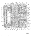
- the details of this mechanical locking device are best seen in Figures 5, 6 and 7.
- each of the turntables 11 is not only sealed with the bearing pin 20 of its connecting element 19 in the associated bearing bore 21 of the bolted to the workpiece carrier 1 piston 22 rotatably mounted, but also limited axially displaceable. On its underside, it bears on an annular surface facing the workpiece carrier 1, and then on the inside of the toothed ring 25a, a planer toothing in the form of a so-called Hirth toothing 45 forms the first locking means on the receiving plate 13 which represents a first locking part.
- a coaxial toothed ring 46 is screwed, which carries on the receiving plate 13 facing planar surface second planer teeth in the form of a second Hirth tooth 46a, the second locking means serving as the second locking element Tooth ring 46 forms.
- the tooth pitches of the two Hirth gears 45, 46a are different from each other.
- a third locking member in the form of a partial disk 47 is arranged, which encloses a ring cylinder 48 which is sealed and axially displaceably mounted on the cylinder liner 24 and limited with this a circumferential cylinder chamber 49.
- annular piston 50 is provided on the inner surface of which the inner cylinder liner 24 is guided displaceably sealed and the outside of the annular cylinder 48 is enclosed.
- the annular cylinder 48 is sealed against the outer surface of the annular piston 50 and defines with the free end face of the annular piston 50 an annular cylinder chamber 51st
- the dividing disk 47 is rotatably connected to the ring cylinder 48 via driving balls 52 inserted in corresponding groove-shaped ball seats, but connected axially non-displaceably. It carries on its overlying planar surfaces two coaxial, arranged in annular regions Hirth teeth 53, 54, the shape and pitch correspond respectively to the opposite Hirth toothing 45 and 46a on the receiving plate 13 and the toothed ring 46.
- the teeth 53, 54 associated with the toothings 45, 46a form locking means on the partial disc 47, which represents a third locking part.
- the cylinder chambers 23, 49, 51 of the lifting cylinder arrangement formed by the cylinder liner 24 and the annular cylinder 48 are via suitable, formed in the workpiece carrier 1 Pressure medium supply channels and a rotary distributor indicated in Figure 3 at 55 connected to a controlled pressure medium supply means of the CNC processing unit, which allows to pressurize the cylinder chambers according to the program with pressure medium or depressurized.
- the multiple tool clamping device described so far operates as follows:
- the Hirth toothing 53 has a tooth pitch of 5 angular degrees corresponding to 72 teeth on the top side of the dividing disk 47 facing the mounting plate 13 and the Hirth toothing 45 associated therewith on the underside of the mounting plate 13.
- the arranged on the opposite underside of the disc 47 Hirth teeth 54 - and this associated Hirth teeth 46a on the toothed ring 45 - is formed with a pitch of 4.5 angular degrees corresponding to 80 teeth.
- the cylinder liner 24 in the axial direction effective annular surface 24b is greater than the effective in the cylinder chamber 49 on the annular cylinder 48 annular surface 48a, which in turn is smaller than the effective in the cylinder chamber 51 on the annular piston 48 annular surface 51a.
- the forces exerted axially on the cylinder liner 24 and the annular cylinder 48 are in the ratio of these axially effective forces Ring surfaces.
- the mounting plate 13 is clamped by means of the dividing disk 47 and the toothed ring 46 in a form-fitting manner with the workpiece carrier 1, the Hirth-toothings ensuring a highly precise positioning of the mounting plate 13 with respect to the workpiece carrier 1.
- the turntables 11 for the next processing cycle must each be further switched by the same angle values about its axis of rotation 12. It is assumed that the switching step for the next operation is 0.5 angular degrees.
- the Hirth serrations 54, 46a remain on the underside of the dividing disk 47 and on the toothed ring 46 under bias with each other while the opposite Hirth serration 53 on the upper side of the dividing disc out of engagement with the Hirth toothing 45 on the underside of the mounting plate 13 comes.
- the mounting plate 13 is directed to the longitudinal axis 3 of the workpiece carrier 1 toward inwardly moves until the Hirth serrations 45 on the underside of the mounting plate 13 and 53 at the top the indexing disk 47 come into engagement and the mounting plate 13 positionally precise lock against the workpiece carrier 1.
- the cylinder chamber 51 is pressurized with pressure medium, while the pressure in the cylinder chamber 23 is lowered.
- the annular cylinder 48 carries out with respect to the rigidly connected to the workpiece carrier 1 annular piston 50 outwardly directed lifting movement, in which he takes over the balls 52, the dividing disk 47, so that arranged on the underside Hirth-toothing 54 with the Hirth serration 46b on the top of the toothed ring 46 is disengaged.
- the Hirth toothing 53 remains on the upper side of the part disc under firm tension with the Hirth toothing 45 on the underside of the tension plate 13 moving outwardly together with the part plate 47.
- the mounting plate 13 is thus moved together with the dividing disk 47 to the outside until the Hirth gears 46a, 54 have completely disengaged, and the end position shown in Figure 5 on the right side is reached, at which the annular surface 24 b of the annular space 23 abuts against the opposite annular surface 22 a of the piston 22.
- the workpiece carrier 1 is rotated about its longitudinal axis 3 by 4.5 degrees, ie a tooth pitch of the Hirth gears 54, 46 in the opposite direction of rotation to the above rotation by 5 degrees, after which the Hirth gears 54, 46 are locked again.
- the cylinder chamber 23 is pressurized again, so that the cylinder chambers 23 and 51 are under the pressure of the pressure medium. Since the axially effective annular surface 24b in the cylinder chamber 23 is greater than the axially effective annular surface 51a in the cylinder chamber 51, arises to the longitudinal axis 3 of the workpiece carrier 1 directed towards the movement of the receiving table 13 and coupled therewith the divider plate 47, in the course the Hirth serrations 54 and 46a engage and lock each other.
- the two above-described two consecutively performed steps for setting a resulting new rotational angular position of the turntable 11 can also be performed in reverse order by first disengaging the Hirth serrations 54, 46a in the manner described and the mounting plate 13 by a predetermined Rotation angle value is rotated in one direction of rotation and then, after locking the disc part 47 with the toothed ring 46, the other Hirth gears 45 and 53 are unlocked to rotate the mounting plate 13 by the desired angular value and then to lock.
- the multiple clamping device contains an interrogator, which determines whether all turntables 11 are properly locked on their Hirth gears 45, 53 and 54, 46 a.
- This interrogation device has interrogation elements in the form of cylindrical interrogation pins or sliders 55, which are mounted longitudinally displaceable in associated with the bearing bore 21 of the respective turntable 11 coaxial bores 56 of the workpiece carrier.
- Each interrogation slide 55 is located on the front side of the bearing pin 20 of the associated receiving plate 13 and thus scans its axial position with respect to the workpiece carrier 1 from.
- Each of the interrogation slide 55 carries on its in the workpiece carrier 1 inwardly facing end face an integrally formed link member 57, which extends only to the respective longitudinal center plane of the interrogator and occupies only a quadrant whose circular face.
- the slide member 57 is provided with a continuous semi-cylindrical recess 58 (see Fig. 5) which is perpendicular to the longitudinal center axis of the interrogator slider 55.
- all query slide 55 respectively in groups of four interrogators, in the manner shown in Figure 5 way pushed together so that their four semi-cylindrical recesses 58 complement to a continuous cylindrical bore, which lies at the intersection of the diagonals of the square cross-sectional shape of the workpiece carrier 1.
- An interrogation rod 61 displaceably arranged in a longitudinal bore 60 of the workpiece carrier 1 which is coaxial with the longitudinal center axis 3 is coupled to an actuating cylinder 62 and adapted to axially adjust the interrogation rod 61 with respect to the workpiece body 1.
- a position sensor indicated at 630 outputs a control signal to the controller of the CNC machining center depending on the axial position of the interrogation rod 61.
- the interrogation rod 61 can be inserted into the workpiece body 1, whereby the sensor 630 emits a corresponding signal.
- dividing disk 47 further such dividing disks may be provided which have locking means, in particular Hirth gearings, with different angular pitches, so that a practically arbitrarily fine subdivision of the switching movement into angular increments can be achieved.
- a major advantage of the new tensioner is that it is characterized by a small footprint, so that several of these tensioners can be combined into a multi-tensioning device, in which, as described, a plurality of turntables 11, distributed over several levels, to arranged a common workpiece carrier are.
- the rotational movement required for the positioning of the turntables is derived in the described embodiment for all turntables 11 of a rotating NC axis, resulting in a very economical solution.
- the dividing discs 47 do not require their own additional drive means and associated control means.
- the clamping device ensures a very precise and stable positioning of the workpieces, whereby a change of the respective position in small angle increments (smaller than eg an angular degree) is readily possible.
- the drive gear 33 ( Figure 3) can also be rotated by the gear motor 38 relative to the workpiece carrier 1, so as to provide an additional, independent of the rotation of the workpiece carrier 1 and its longitudinal axis 3 rotation of the turntables eleventh to achieve their respective axis of rotation 12.
- the simple, closed construction of the new clamping device also provides the prerequisite for use in critical areas, as they are frequently encountered in metalworking, due to the influence of coolants, oils, grinding dust changing temperatures, chips and the like.
Landscapes
- Engineering & Computer Science (AREA)
- Mechanical Engineering (AREA)
- Machine Tool Units (AREA)
- Machine Tool Positioning Apparatuses (AREA)
- Feeding Of Workpieces (AREA)
- Jigs For Machine Tools (AREA)
- Drilling And Boring (AREA)
Claims (16)
- Dispositif de serrage, en particulier pour pièces à usiner sur plusieurs faces, avec- un porte-pièce (1),- au moins un plateau tournant (11) agencé pour recevoir des pièces et monté sur le porte-pièce (1) en tournant autour d'un axe de rotation (12),- un dispositif de verrouillage sur le porte-pièce, associé au plateau tournant (11) par complémentarité de formes, grâce auquel le plateau tournant (11) peut être verrouillé avec précision dans une position angulaire déterminée par rapport au porte-pièce (1), le dispositif de verrouillage comportant :- au moins trois pièces de verrouillage (13, 47, 46), coaxiales entre elles, parmi lesquelles une première pièce de verrouillage (13) est solidaire du plateau tournant (11) et une deuxième pièce de verrouillage (46) est solidaire du porte-pièce (1), tandis qu'au moins une troisième pièce de verrouillage (47) est disposée entre la première (13) et la deuxième pièce de verrouillage (46) et est montée rotative par rapport au porte-pièce (1), toutes les pièces de verrouillage portant sur les surfaces planes tournées les unes vers les autres des moyens de verrouillage (45, 53 ; 46a, 54) coopérant entre eux par paires et qui, par un mouvement axial relatif des pièces de verrouillage entre elles, peuvent être amenés dans une position de dégagement ou d'engagement, et- des moyens d'actionnement destinés à amener les moyens de verrouillage des pièces de verrouillage sélectivement en position de dégagement ou d'engagement, de telle sorte que la troisième pièce de verrouillage (47), au nombre d'au moins une, soit toujours maintenue engagée par ses moyens de verrouillage avec au moins l'une des pièces de verrouillage adjacentes, et- un dispositif d'entraînement couplé au plateau tournant (11), grâce auquel le plateau tournant peut tourner d'une valeur angulaire prédéterminée autour de son axe de rotation (11), soit seul avec la première pièce de verrouillage (13), soit avec la première ainsi qu'avec la troisième pièce de verrouillage (47), engagée avec celle-ci.
- Dispositif de serrage selon la revendication 1, caractérisé en ce que les moyens de verrouillage sont formés chacun d'une denture Hirth (5, 53 ; 46a, 54).
- Dispositif de serrage selon la revendication 1 ou 2, caractérisé en ce que les moyens de verrouillage (45) de la première pièce de verrouillage (13) et les moyens de verrouillage (53) de la deuxième pièce de verrouillage (47) qui leur sont associés possèdent un autre pas angulaire que les moyens de verrouillage (46a) de la deuxième pièce de verrouillage (46) et les moyens de verrouillage (54) de la troisième pièce de verrouillage (47) qui leur sont associés.
- Dispositif de serrage selon la revendication 1 ou 2, caractérisé en ce que la troisième pièce de verrouillage (47), au nombre d'au moins une, est montée folle entre la première et la deuxième pièce de verrouillage (13, 46).
- Dispositif de serrage selon la revendication 1, caractérisé en ce que le plateau tournant (11) possède une denture droite (25) ou est solidaire en rotation de celle-ci, de manière à être accouplé par complémentarité de formes avec des moyens de transmission (26, 31) du dispositif d'entraînement (33).
- Dispositif de serrage selon l'une des revendications précédentes, caractérisé en ce que les moyens d'actionnement possèdent un dispositif de levage grâce auquel peuvent être déplacées axialement, relativement l'un à l'autre, la première et/ou la deuxième pièce de verrouillage (13, 46) et/ou la troisième pièce de verrouillage (47), au nombre d'au moins une.
- Dispositif de serrage selon la revendication 6, caractérisé en ce que le dispositif de levage est actionné par un fluide sous pression.
- Dispositif de serrage selon la revendication 7, caractérisé en ce que le dispositif de levage possède au moins deux vérins de levage (24, 48) coaxiaux avec l'axe de rotation (12), pouvant recevoir un fluide sous pression, qui sont montés réglables dans la direction axiale par rapport au porte-pièce (1) et dont l'un (24) est couplé à la première (13) ou à la deuxième (46) pièce de verrouillage et l'autre (48) est couplé à la troisième pièce de verrouillage (47), au nombre d'au moins une.
- Dispositif de serrage selon la revendication 8, caractérisé en ce que le premier vérin de levage (24) est couplé avec la première (13) ou la deuxième (45) pièce de verrouillage, et le deuxième vérin de levage (48) avec la troisième pièce de verrouillage (47) associée, de manière à permettre la rotation mais de manière solidaire dans la direction axiale.
- Dispositif de serrage selon l'une des revendications précédentes, caractérisé en ce que la troisième pièce de verrouillage, au nombre d'au moins une, prend la forme d'un plateau diviseur (47) qui, sur chacun des deux côtés plans opposés, porte un moyen de verrouillage (53, 54).
- Dispositif de serrage selon l'une des revendications précédentes, caractérisé en ce que la troisième pièce de verrouillage (47), au nombre d'au moins une, lorsqu'elle est déverrouillée par rapport à la première ou à la deuxième pièce de verrouillage (13, 46), est maintenue engagée ou verrouillée avec l'autre pièce de verrouillage.
- Dispositif de serrage selon l'une des revendications précédentes, caractérisé en ce que le porte-pièce (1) est de section polygonale et porte au moins deux surfaces de bridage (2) parallèles à son axe longitudinal et en ce qu'au moins un plateau tournant (11) est disposé sur chaque surface de bridage.
- Dispositif de serrage selon la revendication 11, caractérisé en ce que chaque surface de bridage (2) du porte-pièce conformé en poutre porte au moins deux plateaux tournants (11) dont les axes de rotation (12) se situent dans un plan commun passant par l'axe longitudinal du porte-pièce.
- Dispositif de serrage selon la revendication 12 ou 13, caractérisé en ce que le dispositif d'entraînement possède une source d'entraînement commune à tous les plateaux tournants (11), couplée par complémentarité de forme avec les moyens de transmission des plateaux tournants (11).
- Dispositif de serrage selon la revendication 14, caractérisé en ce que la source commune d'entraînement possède un pignon central d'entraînement (33), avec lequel les moyens de transmission sont engrenés, en ce que le porte-pièce (1) est monté dans des moyens de paliers à rotation autour de son axe longitudinal (3) et en ce que le pignon d'entraînement (33) peut être immobilisé par rapport aux moyens de palier tout en pouvant tourner.
- Dispositif de serrage selon la revendication 14, caractérisé en ce que la source commune d'entraînement peut être commandée indépendamment du mouvement de rotation du porte-pièce (1) autour de son axe longitudinal (3).
Applications Claiming Priority (2)
| Application Number | Priority Date | Filing Date | Title |
|---|---|---|---|
| DE10044915A DE10044915B4 (de) | 2000-09-12 | 2000-09-12 | Spannvorrichtung, insbesondere für mehrseitig zu bearbeitende Werkstücke |
| DE10044915 | 2000-09-12 |
Publications (2)
| Publication Number | Publication Date |
|---|---|
| EP1186373A1 EP1186373A1 (fr) | 2002-03-13 |
| EP1186373B1 true EP1186373B1 (fr) | 2006-05-31 |
Family
ID=7655828
Family Applications (1)
| Application Number | Title | Priority Date | Filing Date |
|---|---|---|---|
| EP01119316A Expired - Lifetime EP1186373B1 (fr) | 2000-09-12 | 2001-08-10 | Moyen de serrage, notamment pour pièces à usiner sur plusieurs faces |
Country Status (4)
| Country | Link |
|---|---|
| US (1) | US6629345B2 (fr) |
| EP (1) | EP1186373B1 (fr) |
| AT (1) | ATE327859T1 (fr) |
| DE (2) | DE10044915B4 (fr) |
Families Citing this family (24)
| Publication number | Priority date | Publication date | Assignee | Title |
|---|---|---|---|---|
| DE10233869B4 (de) * | 2002-07-25 | 2005-12-08 | Roland Huber | Nachrüstbarer Aufsatztisch für Werkstückbearbeitungsmaschinen |
| EP1593455B1 (fr) * | 2004-04-08 | 2006-11-15 | DM2 di Duina Gianfranco S.r.l. | Dispositif de serrage de pièces pour les stations de travail, machines transfer, etc. |
| CN100515663C (zh) * | 2006-03-10 | 2009-07-22 | 鸿富锦精密工业(深圳)有限公司 | 成型方法及夹具 |
| CN102642132A (zh) * | 2012-04-28 | 2012-08-22 | 苏州市达圣机械有限公司 | 一种机床加工中心的工作台 |
| CN102626868B (zh) * | 2012-04-28 | 2013-11-20 | 苏州市达圣机械有限公司 | 机床加工中心的工作台 |
| CN103252663A (zh) * | 2013-04-19 | 2013-08-21 | 苏州弘远机械制造有限公司 | 一种主轴套粗加工治具及加工工艺 |
| CN103433782B (zh) * | 2013-08-31 | 2015-08-26 | 荆州市祥达机械制造有限公司 | 汽车电动转向器蜗轮蜗杆壳体专用四轴夹具 |
| CN104802023B (zh) * | 2014-01-24 | 2017-06-13 | 富鼎电子科技(嘉善)有限公司 | 翻转装置 |
| EP2929979A1 (fr) * | 2014-04-08 | 2015-10-14 | Etxe-Tar, S.A. | Machine-outil pour l'usinage de barres de connexion |
| DE102014106331A1 (de) * | 2014-05-07 | 2015-11-12 | Amann Girrbach Ag | Werkstückträger |
| KR101523364B1 (ko) * | 2015-02-10 | 2015-05-28 | 고재식 | 지그 조립체 및 이를 구비하는 가공장치 |
| CN104786082B (zh) * | 2015-04-24 | 2016-11-23 | 铁岭天河机械制造有限责任公司 | 汽车发动机调温器座加工卡具 |
| CN106181507A (zh) * | 2015-05-07 | 2016-12-07 | 哈尔滨飞机工业集团有限责任公司 | 一种多面可旋转工装 |
| CN104889771A (zh) * | 2015-06-03 | 2015-09-09 | 济南大学 | 一种多工位柔性夹持工装 |
| CN105382630B (zh) * | 2015-12-02 | 2017-11-07 | 贵州汉诺威数控机床有限公司 | 一种多功能复合分度机构 |
| CN108890488A (zh) * | 2018-07-19 | 2018-11-27 | 李国理 | 一种加工与存取同步的多工位设备 |
| CN109128934B (zh) * | 2018-09-27 | 2019-09-24 | 杭州昌鼎机械有限公司 | 汽车电池盒部件机加工回转夹具 |
| KR102093074B1 (ko) * | 2019-09-26 | 2020-05-26 | 이종규 | 화기용 브래킷 제조방법 |
| CN111215919A (zh) * | 2020-03-18 | 2020-06-02 | 珠海格力智能装备有限公司 | 工作台及具有其的机床 |
| CN112025350A (zh) * | 2020-08-20 | 2020-12-04 | 南京中车浦镇城轨车辆有限责任公司 | 一种多功能堆叠式工艺装置 |
| CN113231851B (zh) * | 2021-05-18 | 2022-03-11 | 衢州职业技术学院 | 一种数控机床主轴箱的加工系统及其加工工艺 |
| CN114633133B (zh) * | 2022-05-20 | 2022-08-09 | 四川仨川航空科技股份有限公司 | 一种飞机异形零件夹持辅助装置及其夹持方法 |
| KR102559939B1 (ko) * | 2022-09-15 | 2023-07-27 | 박웅각 | 클러치 샤프트용 지그 시스템 |
| CN115847115B (zh) * | 2023-02-28 | 2023-05-23 | 象山申达轿车配件有限公司 | 差速器壳体及夹具 |
Family Cites Families (14)
| Publication number | Priority date | Publication date | Assignee | Title |
|---|---|---|---|---|
| US3049032A (en) * | 1959-08-20 | 1962-08-14 | Bernard W Schabot | Rotary precision work holder |
| US3146640A (en) * | 1961-08-02 | 1964-09-01 | Michigan Tool Co | Indexing device |
| DE1962097C3 (de) * | 1969-12-11 | 1982-09-09 | Fibro Gmbh, 7102 Weinsberg | Rundschalttisch |
| US3846912A (en) * | 1972-01-10 | 1974-11-12 | R Newbould | Indexing mechanism |
| US3908484A (en) * | 1973-03-22 | 1975-09-30 | Frederick I Degen | Dividing head |
| US4353271A (en) * | 1980-05-15 | 1982-10-12 | A.G. Davis Gage And Engineering Co. | Multiple position rotary index table |
| US4380939A (en) * | 1980-07-01 | 1983-04-26 | Cameron Iron Works, Inc. | Rotary indexing table |
| US4463488A (en) * | 1981-03-17 | 1984-08-07 | A. G. Davis Gage & Engineering Co. | Indexing work table |
| CA1199050A (fr) * | 1981-10-26 | 1986-01-07 | Daniel J. Pieczulewski | Table rotative a piston hydraulique montee sur roulements a charge pre-etablie |
| ATE58855T1 (de) * | 1986-03-07 | 1990-12-15 | Chuang Kuo Huey | Getriebe eines revolverkopfes bestehend aus einer zwillingsscheibe fuer cnc-maschinen. |
| DE3817937A1 (de) * | 1988-05-26 | 1989-11-30 | Sauter Kg Feinmechanik | Werkzeugrevolver |
| US5450771A (en) * | 1993-06-16 | 1995-09-19 | Utica Enterprises, Inc. | Rotary index table assembly |
| US5682658A (en) * | 1996-03-04 | 1997-11-04 | Utica Enterprises, Inc. | Rotary index table assembly |
| DE19840942C1 (de) * | 1998-09-08 | 2000-03-09 | Albeck Gmbh | Mehrfach-Spannvorrichtung |
-
2000
- 2000-09-12 DE DE10044915A patent/DE10044915B4/de not_active Expired - Fee Related
-
2001
- 2001-08-10 DE DE50109930T patent/DE50109930D1/de not_active Expired - Fee Related
- 2001-08-10 AT AT01119316T patent/ATE327859T1/de not_active IP Right Cessation
- 2001-08-10 EP EP01119316A patent/EP1186373B1/fr not_active Expired - Lifetime
- 2001-09-10 US US09/949,609 patent/US6629345B2/en not_active Expired - Fee Related
Also Published As
| Publication number | Publication date |
|---|---|
| DE50109930D1 (de) | 2006-07-06 |
| EP1186373A1 (fr) | 2002-03-13 |
| DE10044915A1 (de) | 2002-04-18 |
| US20020069498A1 (en) | 2002-06-13 |
| ATE327859T1 (de) | 2006-06-15 |
| US6629345B2 (en) | 2003-10-07 |
| DE10044915B4 (de) | 2007-07-26 |
Similar Documents
| Publication | Publication Date | Title |
|---|---|---|
| EP1186373B1 (fr) | Moyen de serrage, notamment pour pièces à usiner sur plusieurs faces | |
| DE19840942C1 (de) | Mehrfach-Spannvorrichtung | |
| EP0596956B1 (fr) | Revolver porte-outils pour machine-outil, en particulier pour un tour | |
| EP1961515B2 (fr) | Dispositif de couplage et élément de couplage pour un porte-outils ou des dispositifs de serrage de pièces usinées | |
| DE2739810A1 (de) | Werkzeugmaschine | |
| DE2814013A1 (de) | Baueinheit mit einem drehbaren arbeitstisch und einer schrittschalt- steuereinrichtung | |
| DE2819412C3 (de) | Rundschalttisch | |
| DE3941480C2 (fr) | ||
| DE2308984C2 (de) | Schalttisch-Automat | |
| EP0989922B1 (fr) | Robot de montage ou de fabrication et poste de travail pour un tel robot | |
| DE2707648C2 (de) | Werkstückaufnahme für eine Senkrechträummaschine zum Räumen von ringförmigen Werkstücken | |
| DE3619999C2 (fr) | ||
| DE2949709B1 (de) | Einrichtung zum Indexieren und Zentrieren bezueglich der Fraesspindelachse eines Winkelfraeskopfes an der Bodenplatte eines Fraesspindelstockes | |
| DE3209512A1 (de) | Rundschalttisch | |
| DE3990008C1 (fr) | ||
| EP0962280B1 (fr) | Dispositif d'alignement | |
| EP2618955A1 (fr) | Tête d'outil pour une utilisation dans des machines-outils | |
| DE4235095C2 (de) | Werkzeugrevolver | |
| DE2840129A1 (de) | Befestigungsvorrichtung zum halten eines werkstuecks an einer werkzeugmaschine | |
| DE2508571C2 (de) | Rundtaktmaschine zur aufeinanderfolgenden Bearbeitung von Fittings und dergl. Werkstücken | |
| EP1128930A1 (fr) | Tete d'outil a logement de broche | |
| DE3231782A1 (de) | Nc-gesteuerte revolver-drehmaschine | |
| DE3034071A1 (de) | Fraesmaschine mit einer werkzeugausstossvorrichtung. | |
| DE4135735C1 (fr) | ||
| DE3109198C2 (de) | Fräsmaschine zum Fräsen von Nuten in Bohrungswandungen von Werkstücken |
Legal Events
| Date | Code | Title | Description |
|---|---|---|---|
| PUAI | Public reference made under article 153(3) epc to a published international application that has entered the european phase |
Free format text: ORIGINAL CODE: 0009012 |
|
| AK | Designated contracting states |
Kind code of ref document: A1 Designated state(s): AT BE CH CY DE DK ES FI FR GB GR IE IT LI LU MC NL PT SE TR Kind code of ref document: A1 Designated state(s): AT CH DE FR GB IT LI |
|
| AX | Request for extension of the european patent |
Free format text: AL;LT;LV;MK;RO;SI |
|
| 17P | Request for examination filed |
Effective date: 20020531 |
|
| AKX | Designation fees paid |
Free format text: AT CH DE FR GB IT LI |
|
| GRAP | Despatch of communication of intention to grant a patent |
Free format text: ORIGINAL CODE: EPIDOSNIGR1 |
|
| GRAS | Grant fee paid |
Free format text: ORIGINAL CODE: EPIDOSNIGR3 |
|
| GRAA | (expected) grant |
Free format text: ORIGINAL CODE: 0009210 |
|
| AK | Designated contracting states |
Kind code of ref document: B1 Designated state(s): AT CH DE FR GB IT LI |
|
| REG | Reference to a national code |
Ref country code: CH Ref legal event code: EP Ref country code: GB Ref legal event code: FG4D Free format text: NOT ENGLISH |
|
| REG | Reference to a national code |
Ref country code: CH Ref legal event code: NV Representative=s name: KIRKER & CIE SA |
|
| REF | Corresponds to: |
Ref document number: 50109930 Country of ref document: DE Date of ref document: 20060706 Kind code of ref document: P |
|
| PGFP | Annual fee paid to national office [announced via postgrant information from national office to epo] |
Ref country code: AT Payment date: 20060816 Year of fee payment: 6 |
|
| GBT | Gb: translation of ep patent filed (gb section 77(6)(a)/1977) |
Effective date: 20060830 |
|
| ET | Fr: translation filed | ||
| PLBE | No opposition filed within time limit |
Free format text: ORIGINAL CODE: 0009261 |
|
| STAA | Information on the status of an ep patent application or granted ep patent |
Free format text: STATUS: NO OPPOSITION FILED WITHIN TIME LIMIT |
|
| 26N | No opposition filed |
Effective date: 20070301 |
|
| PG25 | Lapsed in a contracting state [announced via postgrant information from national office to epo] |
Ref country code: AT Free format text: LAPSE BECAUSE OF NON-PAYMENT OF DUE FEES Effective date: 20070810 |
|
| PGFP | Annual fee paid to national office [announced via postgrant information from national office to epo] |
Ref country code: CH Payment date: 20080814 Year of fee payment: 8 Ref country code: DE Payment date: 20080831 Year of fee payment: 8 |
|
| PGFP | Annual fee paid to national office [announced via postgrant information from national office to epo] |
Ref country code: FR Payment date: 20080813 Year of fee payment: 8 Ref country code: IT Payment date: 20080823 Year of fee payment: 8 |
|
| PGFP | Annual fee paid to national office [announced via postgrant information from national office to epo] |
Ref country code: GB Payment date: 20080821 Year of fee payment: 8 |
|
| REG | Reference to a national code |
Ref country code: CH Ref legal event code: PL |
|
| GBPC | Gb: european patent ceased through non-payment of renewal fee |
Effective date: 20090810 |
|
| PG25 | Lapsed in a contracting state [announced via postgrant information from national office to epo] |
Ref country code: CH Free format text: LAPSE BECAUSE OF NON-PAYMENT OF DUE FEES Effective date: 20090831 Ref country code: LI Free format text: LAPSE BECAUSE OF NON-PAYMENT OF DUE FEES Effective date: 20090831 |
|
| REG | Reference to a national code |
Ref country code: FR Ref legal event code: ST Effective date: 20100430 |
|
| PG25 | Lapsed in a contracting state [announced via postgrant information from national office to epo] |
Ref country code: FR Free format text: LAPSE BECAUSE OF NON-PAYMENT OF DUE FEES Effective date: 20090831 Ref country code: DE Free format text: LAPSE BECAUSE OF NON-PAYMENT OF DUE FEES Effective date: 20100302 |
|
| PG25 | Lapsed in a contracting state [announced via postgrant information from national office to epo] |
Ref country code: GB Free format text: LAPSE BECAUSE OF NON-PAYMENT OF DUE FEES Effective date: 20090810 |
|
| PG25 | Lapsed in a contracting state [announced via postgrant information from national office to epo] |
Ref country code: IT Free format text: LAPSE BECAUSE OF NON-PAYMENT OF DUE FEES Effective date: 20090810 |