EP1184319A2 - Gerät zum Abtrennen von Bahnen aus Papier und/oder Folie von einer Papier- bzw. Folienrolle - Google Patents
Gerät zum Abtrennen von Bahnen aus Papier und/oder Folie von einer Papier- bzw. Folienrolle Download PDFInfo
- Publication number
- EP1184319A2 EP1184319A2 EP01116374A EP01116374A EP1184319A2 EP 1184319 A2 EP1184319 A2 EP 1184319A2 EP 01116374 A EP01116374 A EP 01116374A EP 01116374 A EP01116374 A EP 01116374A EP 1184319 A2 EP1184319 A2 EP 1184319A2
- Authority
- EP
- European Patent Office
- Prior art keywords
- support
- cutting
- paper
- film
- support plate
- Prior art date
- Legal status (The legal status is an assumption and is not a legal conclusion. Google has not performed a legal analysis and makes no representation as to the accuracy of the status listed.)
- Granted
Links
Images


Classifications
-
- B—PERFORMING OPERATIONS; TRANSPORTING
- B65—CONVEYING; PACKING; STORING; HANDLING THIN OR FILAMENTARY MATERIAL
- B65H—HANDLING THIN OR FILAMENTARY MATERIAL, e.g. SHEETS, WEBS, CABLES
- B65H35/00—Delivering articles from cutting or line-perforating machines; Article or web delivery apparatus incorporating cutting or line-perforating devices, e.g. adhesive tape dispensers
- B65H35/0006—Article or web delivery apparatus incorporating cutting or line-perforating devices
- B65H35/0073—Details
- B65H35/008—Arrangements or adaptations of cutting devices
- B65H35/0086—Arrangements or adaptations of cutting devices using movable cutting elements
-
- A—HUMAN NECESSITIES
- A47—FURNITURE; DOMESTIC ARTICLES OR APPLIANCES; COFFEE MILLS; SPICE MILLS; SUCTION CLEANERS IN GENERAL
- A47K—SANITARY EQUIPMENT; ACCESSORIES THEREFOR, e.g. TOILET ACCESSORIES
- A47K10/00—Body-drying implements; Toilet paper; Holders therefor
- A47K10/24—Towel dispensers; Toilet paper dispensers
- A47K10/32—Dispensers for paper towels or toilet paper
- A47K10/34—Dispensers for paper towels or toilet paper dispensing from a web, e.g. with mechanical dispensing means
- A47K10/36—Dispensers for paper towels or toilet paper dispensing from a web, e.g. with mechanical dispensing means with mechanical dispensing, roll switching or cutting devices
- A47K10/3631—The cutting devices being driven manually
-
- B—PERFORMING OPERATIONS; TRANSPORTING
- B65—CONVEYING; PACKING; STORING; HANDLING THIN OR FILAMENTARY MATERIAL
- B65H—HANDLING THIN OR FILAMENTARY MATERIAL, e.g. SHEETS, WEBS, CABLES
- B65H2301/00—Handling processes for sheets or webs
- B65H2301/50—Auxiliary process performed during handling process
- B65H2301/51—Modifying a characteristic of handled material
- B65H2301/515—Cutting handled material
- B65H2301/5154—Cutting handled material from hand-held or table dispenser
-
- B—PERFORMING OPERATIONS; TRANSPORTING
- B65—CONVEYING; PACKING; STORING; HANDLING THIN OR FILAMENTARY MATERIAL
- B65H—HANDLING THIN OR FILAMENTARY MATERIAL, e.g. SHEETS, WEBS, CABLES
- B65H2701/00—Handled material; Storage means
- B65H2701/10—Handled articles or webs
- B65H2701/17—Nature of material
- B65H2701/175—Plastic
- B65H2701/1752—Polymer film
Definitions
- the invention relates to a device according to the preamble of claim 1 or 2, alternatively that of claim 3.
- a device is in EP-B-265 552 described.
- each depot with a support plate provided for a paper or film roll one above the other in a housing.
- the Housing is covered with a cover that is used to load one or both Depots with a roll of paper or film can be removed from the housing if necessary or can be placed on the housing.
- the cover has one opening assigned to a depot, whose upper boundary edge together with a further area of the housing a passage slot for the paper or Foil forms.
- each assigned - can be moved transversely to the removal direction of the paper or film guided cutting slide provided.
- the cutting knife of each cutting slide is each assigned a cutting channel running parallel to the longitudinal direction of the mounting plate, which is located in a support cutting bar, which in its full, in Direction of removal of the paper or the film extending under a right angle down to connects to the platen of the depot in question.
- the cutting channel is on the one hand by an edge in the removal direction of the Paper or the film lying in front of the cutting channel support and grip area of the Support cutting bar and on the other hand by an edge of one in the removal direction of the Paper or the film behind the cutting channel support area of the Support interface strip limited.
- the construction of the known device is relatively complicated and regarding the material consumption for its manufacture - as an inevitable consequence of the complicated construction - relatively complex. This applies in particular to the execution the support cutting bar in cooperation with the one carrying the paper or foil roll Platen; in the known device closes the support interface at a right angle pointing down to the front end of the platen.
- a plurality of stiffening ribs is provided, the back of the support interface with the underside of the support plate connect.
- the known device consists of plastic and is manufactured by injection molding.
- this device has also with regard to the assembly effort and its functionality certain disadvantages that the leadership of the Cutters affect.
- the present invention has for its object a device of the beginning mentioned genus in the sense of further improving it from the construction ago is much simpler and that for its production at least same stability, considerably less material (plastic) is necessary. It should also Device can also be improved aesthetically to the extent that it is a more pleasing, modern and more self-contained than that known device.
- the need for such stiffening ribs does not apply because the forces mentioned in a device according to the invention can be introduced practically directly into the front end of the platen, which is itself supported directly or indirectly on the mounting wall.
- Claim 4 calls a preferred embodiment for the support and grip area Support interface of the device, in which the upper, free edge of the support and Grip area receives the function of a holding edge for the paper or film roll.
- Claim 5 relates to an advantageous dimensioning of the extent of the support and Grip area.
- Claims 9 to 12 name alternative solutions for essentially that Area of the device according to the invention, the support cutting bar and that subsequent front end of the platen as well as within the area of the Support cutting bar located cutting channel includes.
- claims 14 and 15 describe - as already mentioned above - a preferred solution for the design of the guide means for guiding the Cutting slide on the mentioned upper boundary edge of the depot associated opening of the cover.
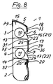
- 1, 2 and 8 show a device 1, which consists essentially of a housing 2 with Depots 3 and 4 to hold one roll of paper or film and one on Housing 2 releasably attached cover 5 with in the region of an opening 6 and 7 respectively Cover 5 provided cutting slides 8 and 9 there. - In Figs. 2 and 8 the cutting slides 8 and 9 are not shown for reasons of clarity.
- the depot 3 is used, for example, for storing a film roll 10 made of plastic film. in particular so-called transparent film - used while the depot 4 for storage a foil roll 11 made of aluminum foil is used.
- the cutting slides 8 and 9 assigned to the depots 3, 4 do not have one in detail Cutting knife 12 shown in more detail (see FIG. 7), which - Cutting sheets from plastic film or cutting sheets from Aluminum foil - is adapted in its shape and functionality; That's how it is Cutting blades provided for cutting plastic film than in the cutting slide fixed cutting knife with two in the cutting area itself provided opposite and an acute angle with the cutting plane forming cutting edges, while cutting aluminum foil provided cutting knife as rotatably mounted in the cutting slide, disc-shaped cutting knife (circular knife) is executed.
- - To the Cutting knives close on both sides of the cutting knife in a manner known per se existing, made of rubber or similar material pressure rollers when removing the film or paper on one or the other side of the Support the cutting channel on areas of the housing or cover.
- the depots 3, 4 are downward through a carrying the film roll 10 and 11 respectively Platen 13 or 14 limited.
- the platen 13 and 14 is obliquely from inclined (see Fig. 2, 3 and 8) and forms at least essentially one Guide level for the film roll 10 or 11.
- the slope of the support plates 13, 14 is dimensioned such that the film roll 10 lying on the support plate 13 or 14 or 11 under the influence of their own weight always one in the direction of the front End of the support plate 13 or 14 drive force to be directed onto the film roll 10 or 11 acts - Attachment of the device in the intended manner on a substantially vertical mounting wall provided.
- the relevant film roll 10 or 11 is always close to the relevant one Cutting slide on one area of the device, namely in a subsequent area descriptive retaining edge.
- the depots through the support plate of the one above Depots or delimited by an upper end region 15 of the housing 2, while the rearward limitation of the depots 3, 4 essentially by the Mounting wall for the device is formed.
- the front boundary of the depots 3, 4 is partly by one of the Support plate 13 or 14 protruding projection 16 or 17 molded onto it formed and in part by an overlying area 18 and 19 of the cover 5th
- the regions 18 and 19 of the cover 5 lying one behind the other in the vertical direction include the already mentioned opening 6 of the cover 5, while the area 19 and a region of the cover 5 designated by 20 has the already mentioned opening 7 of FIG Include cover 5.
- the extensions 16, 17 of the platen 13 and 14 belong to - as moldings of the Support plate 13 or 14 - to housing 2 and form a support and grip area 21 or 22 of a one referred to collectively as a support interface strip 23 or 24 Area of the device 1.
- the Cutting knife of the cutting slide 8 or 9 is assigned.
- the cutting channel 27 or 28 is on the one hand by an edge 29 of the in the removal direction of the paper or of the film in front of the cutting channel 27 or 28 lying and grip area 21st or 22 of the support cutting bar 23 or 24 and on the other hand by an edge 30 of the in Removal direction of the paper or the film on the support and grip area 21 or 22 following support area 25 and 26 of the support interface 23 and 24 limited.
- the support and grip area 21 or 22 formed by the extension 16 or 17 respectively Support interface strip 23 or 24 of the device 1 has an upper, free edge which the Function of a holding edge 33 and 34 for the film roll 10 and 11 receives.
- This Holding edge 33 or 34 extends in the case of the embodiment except for approximately that half the diameter of the film roll 10 or 11 corresponding height.
- a certain roughness (the front) of the support and Handle area 21 and 22 ensures that despite the plastic film outgoing adhesive forces a relatively easy removal or lifting of the film from the support and grip area 21 or 22 is possible.
- the cutting slide 8 or 9 is directly on the upper, designated 35 and 36 respectively Boundary edge of the opening 6 or 7 of the cover 5 slidably guided (see also Fig. 7), which together with the mentioned holding edge 33 and 34, respectively Passage slot for the paper or the film forms.
- the boundary edge 35 or 36 has a bulge-like extension 37 in cross section on the one with the cutting knife of the cutting slide 8 or 9 opposite, upper end of the cutting slide 8 and 9 provided guide groove 39 corresponds to that which extends behind the bead-like extension 37 Formations 72 is provided.
- the guide groove 39 is on the one hand from the 41 designated upper end of the 43 designated front wall part of the Cutting slide 8 and 9 and on the other hand from those designated 44, 45 lateral wall parts of the cutting slide 8 or 9 integrally formed extensions 49 and 50 formed.
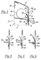
- Fig. 4 shows an adjoining the front end of a support plate 53
- Support cutting bar 54 with a cutting channel 55 which is only of areas of the housing, not shown, is limited, both with the 56th designated support and grip area as well as the support area designated 57
- Fig. 5 shows one adjoining the front end of a support plate 59 Support cutting bar 60 with a cutting channel 61, which is only of areas the cover, not shown, is limited, the one designated by 62 Support and grip area of the support cutting bar 60 from one to the support plate 59 molded-on extension 63 together with a also not on illustrated housing - namely on an extension 64 of the support plate 59 - Supporting wall area of the cover is formed, on the under Inclusion of the cutting channel 61, the support area designated 65 Support interface 60 connects.
- FIG. 6 shows a support cutting bar 67 bearing against the front end of a support plate 66 with a cutting channel 68, which is limited only by areas of the cover (not shown).
- the support and grip area of the support cutting bar 67 which is designated by 69, is formed by a strip-like area 70 which is formed on the support plate 66 - that is to say on the housing - and which is formed on the support plate, including the cutting channel 68 66 supporting, designated 71 support area of the support interface 67 connects.
- fastening holes are provided in areas 74, 75 of the housing 2 of the device 1 for fastening the device to a wall or the like.
Landscapes
- Replacement Of Web Rolls (AREA)
- Control And Other Processes For Unpacking Of Materials (AREA)
- Unwinding Webs (AREA)
- Nonmetal Cutting Devices (AREA)
Abstract
Description
- Fig. 1
- ein erfindungsgemäßes Gerät mit zwei Depots für je eine Papier- bzw. Folienrolle und den Depots zugeordneten Schneidschiebem sowie mit einer Lagermöglichkeit für eine Papiervliesrolle in der Vorderansicht,
- Fig. 2
- das Gerät nach Fig. 1 in der Seitenansicht im Schnitt entsprechend Schnittlinie II-II in Fig. 1,
- Fig. 3
- einen Ausschnitt der Darstellung nach Fig. 2 in größerem Maßstab und mit einer bevorzugten Lösung für die Bildung der Auflageschnittleiste and des Schneidkanals des Gerätes,
- Fig. 4
- eine andere Lösung für die Bildung der Auflageschnittleiste und des Schneidkanals im Schnitt,
- Fig. 5
- eine weitere Lösung für die Bildung der Auflageschnittleiste und des Schrieidkanals im Schnitt,
- Fig. 6
- eine weitere Lösung für die Bildung der Auflageschnittleiste und des Schneidkanals im Schnitt,
- Fig. 7
- einen der in Fig. 1 gezeigten Schneidschieber zusammen mit den mit dem Schneidschieber korrespondierenden Bereichen der Abdeckung bzw. des Gehäuses des Gerätes in der Seitenansicht im Schnitt und in einem gegenüber der Darstellung in Fig. 1 größeren Maßstab, und
- Fig. 8
- eine der Darstellung nach Fig. 2 entsprechende Darstellung, jedoch in größerem Maßstab.
Ergänzend ist noch zu bemerken, dass zur Befestigung des Gerätes an einer Wand oder dgl. Befestigungslöcher in Bereichen 74, 75 des Gehäuses 2 des Gerätes 1 vorgesehen sind.
- 1
- Gerät
- 2
- Gehäuse
- 3
- Depot
- 4
- Depot
- 5
- Abdeckung
- 6
- Öffnung
- 7
- Öffnung
- 8
- Schneidschieber
- 9
- Schneidschieber
- 10
- Folienrolle
- 11
- Folienrolle
- 12
- Schneidmesser
- 13
- Auflageplatte
- 14
- Auflageplatte
- 15
- Abschlussbereich
- 16
- Fortsatz
- 17
- Fortsatz
- 18
- Bereich
- 19
- Bereich
- 20
- Bereich
- 21
- Auflage- und Griffbereich
- 22
- Auflage- und Griffbereich
- 23
- Auflageschnittleiste
- 24
- Auflageschnittleiste
- 25
- Stützbereich
- 26
- Stützbereich
- 27
- Schneidkanal
- 28
- Schneidkanal
- 29
- Kante
- 30
- Kante
- 31
- Fortsatz
- 32
- Fortsatz
- 33
- Haltekante
- 34
- Haltekante
- 35
- Begrenzungskante
- 36
- Begrenzungskante
- 37
- Erweiterung, wulstartig
- 38
- -
- 39
- Führungsnut
- 40
- -
- 41
- Ende, oberes
- 42
- -
- 43
- Wandungsteil, vorderes
- 44
- Wandungsteil, seitliches
- 45
- Wandungsteil, seitliches
- 46
- -
- 47
- -
- 48
- -
- 49
- Fortsatz
- 50
- Fortsatz
- 51
- -
- 52
- -
- 53
- Auflageplatte
- 54
- Auflageschnittleiste
- 55
- Schneidkanal
- 56
- Auflage- und Griffbereich
- 57
- Stützbereich
- 58
- Fortsatz
- 59
- Auflageplatte
- 60
- Auflageschnittleiste
- 61
- Schneidkanal
- 62
- Auflage- und Griffbereich
- 63
- Fortsatz
- 64
- Fortsatz
- 65
- Stützbereich
- 66
- Auflageplatte
- 67
- Auflageschnittleiste
- 68
- Schneidkanal
- 69
- Auflage- und Griffbereich
- 70
- Bereich, leistenartig
- 71
- Stützbereich
- 72
- Ausformungen (am Schneidschieber)
- 73
- -
- 74
- Bereich (für Befestigung)
- 75
- Bereich (für Befestigung)
Claims (15)
- Gerät (1) zum Abtrennen von Bahnen aus Papier und/oder Folie von einer Papierbzw. Folienrolle (10, 11),a) mit einem Gehäuse (2) mit zumindest einem zur Aufnahme einer Papier- oder Folienrolle (10,11) vorgesehenen Depot (3, 4) mit einer Auflageplatte (13, 14) für die Papier- bzw. Folienrolle (10, 11),b) mit einer an die Auflageplatte (13, 14) anschließenden Auflageschnittleiste (23, 24) mit einem in dieser parallel zur Längsrichtung der Auflageplatte (13, 14) verlaufenden, dem Schneidmesser eines Schneidschiebers (8, 9) zugeordneten Schneidkanal (27, 28), der einerseits durch eine Kante (29) eines in Entnahmerichtung des Papiers bzw. der Folie vor dem Schneidkanal (27, 28) liegenden Auflage- und Griffbereiches (21, 22) der Auflageschnittleiste (23, 24) und andererseits durch eine Kante (30) eines in Entnahmerichtung des Papiers bzw. der Folie hinter dem Schneidkanal (27, 28) liegenden Stützbereiches (25, 26) der Auflageschnittleiste (23, 24) begrenzt wird,c) mit einer Abdeckung (5) für das Gehäuse (2), die eine dem Depot (3, 4) zugeordnete Öffnung (5, 6) aufweist, deren obere Begrenzungskante (35, 36) zusammen mit einem weiteren Bereich des Gerätes (1) einen Durchlassschlitz für das Papier bzw. die Folie bildet, undd) mit einem der Auflageschnittleiste (23, 24) zugeordneten, quer zur Entnahmerichtung des Papiers bzw. der Folie an der Abdeckung verschiebbar geführten Schneidschieber (8, 9), gekennzeichnet durch folgendes Merkmal:e) die Auflageschnittleiste (23, 24) schließt derart an die Auflageplatte (13, 14) an, dass der Schneidkanal (27, 28) zumindest annähernd in der Ebene der Auflageplatte 13, 14) liegt.
- Gerät (1) zum Abtrennen von Bahnen aus Papier und/oder Folie von einer Papier- bzw. Folienrolle (10, 11),a) mit einem Gehäuse (2) mit zumindest einem zur Aufnahme einer Papier-oder Folienrolle (10, 11) vorgesehenen Depot (3, 4) mit einer Auflageplatte (13, 14) für die Papier- bzw. Folienrolle (10,11),b) mit einer an die Auflageplatte (13, 14) anschließenden Auflageschnittleiste (23, 24) mit einem in dieser parallel zur Längsrichtung der Auflageplatte (13, 14) verlaufenden, dem Schneidmesser eines Schneidschiebers (8, 9) zugeordneten Schneidkanal (27, 28), der einerseits durch eine Kante (29) eines in Entnahmerichtung des Papiers bzw. der Folie vor dem Schneidkanal (27, 28) liegenden Auflage- und Griffbereiches (21, 22) der Auflageschnittleiste (23, 24) und andererseits durch eine Kante (30) eines in Entnahmerichtung des Papiers bzw. der Folie hinter dem Schneidkanal (27, 28) liegenden Stützbereiches (25, 26) der Auflageschnittleiste (23, 24) begrenzt wird,c) mit einer Abdeckung (5) für das Gehäuse (2), die eine dem Depot (3, 4) zugeordnete Öffnung (5, 6) aufweist, deren obere Begrenzungskante (35, 36) zusammen mit einem weiteren Bereich des Gerätes (1) einen Durchlassschlitz für das Papier bzw. die Folie bildet, undd) mit einem der Auflageschnittleiste (23, 24) zugeordneten, quer zur Entnahmerichtung des Papiers bzw. der Folie an der Abdeckung verschiebbar geführten Schneidschieber (8, 9), gekennzeichnet durch folgende Merkmale:e) die Auflageschnittleiste (23, 24) schließt derart an die Auflageplatte (13, 14) an, dass der Schneidkanal (27, 28) zumindest annähernd in der Ebene der Auflageplatte 13, 14) liegt, undf) der Schneidschieber (8, 9) ist an der erwähnten oberen Begrenzungskante (35, 36) der erwähnten Öffnung (6, 7) der Abdeckung (5) verschiebbar geführt.
- Gerät (1) zum Abtrennen von Bahnen aus Papier und/oder Folie von einer Papierbzw. Folienrolle (10, 11),a) mit einem Gehäuse (2) mit zumindest einem zur Aufnahme einer Papier- oder Folienrolle (10, 11) vorgesehenen Depot (3, 4) mit einer Auflageplatte (13, 14) mit schräg nach vom geneigter Führungsebene für die Papier- bzw. Folienrolle (10, 11),b) mit einer an die Auflageplatte (13, 14) anschließenden Auflageschnittleiste (23, 24) mit einem in dieser parallel zur Längsrichtung der Auflageplatte (13, 14) verlaufenden, dem Schneidmesser eines Schneidschiebers (8, 9) zugeordneten Schneidkanal (27, 28), der einerseits durch eine Kante (29) eines in Entnahmerichtung des Papiers bzw. der Folie vor dem Schneidkanal (27, 28) liegenden Auflage- und Griffbereiches (21, 22) der Auflageschnittleiste (23, 24) und andererseits durch eine Kante (30) eines in Entnahmerichtung des Papiers bzw. der Folie hinter dem Schneidkanal (27, 28) liegenden Stützbereiches (25, 26) der Auflageschnittleiste (23, 24) begrenzt wird,c) mit einer Abdeckung (5) für das Gehäuse (2), die eine dem Depot (3, 4) zugeordnete Öffnung (5, 6) aufweist, deren obere Begrenzungskante (35, 36) zusammen mit einem weiteren Bereich des Gerätes (1) einen Durchlassschlitz für das Papier bzw. die Folie bildet, undd) mit einem der Auflageschnittleiste (23, 24) zugeordneten, quer zur Entnahmerichtung des Papiers bzw. der Folie an der Abdeckung verschiebbar geführten Schneidschieber (8, 9),
gekennzeichnet durch folgende Merkmale:e) die Auflageschnittleiste (23, 24) schließt derart an die Auflageplatte (13, 14) an, dass der Schneidkanal (27, 28) zumindest annähernd in der Ebene der Auflageplatte 13, 14) liegt,f) die Auflageplatte (13, 14) ist schräg nach vom geneigt ausgeführt und bildet zumindest im wesentlichen die Führungsebene für die Papier-bzw. Folienrolle (10, 11), undg) die Auflageschnittleiste (23, 24) bildet mit den Fortätzen (16, 17), einen nach Innen versetzten Griffbereich. - Gerät nach Anspruch 1, 2 oder 3, dadurch gekennzeichnet, dass die dem Schneidkanal (27; 28) gegenüberliegende Kante des Auflage- und Griffbereiches (21, 22) der Auflageschnittleiste (23, 24) eine Haltekante (33, 34) für die Papier- bzw. Folienrolle (10, 11) bildet.
- Gerät nach Anspruch 4, dadurch gekennzeichnet, dass der Auflage- und Griffbereich (21, 22) der Auflageschnittleiste (23, 24) in Entnahmerichtung des Papiers bzw. der Folie derart bemessen ist, dass die Haltekante (33, 34) bis auf eine etwa dem halben Durchmesser der Papier- bzw. Folienrolle (10, 11) entsprechende Höhe reicht.
- Gerät nach Anspruch 1, 2 oder 3, dadurch gekennzeichnet, dass der über der Ebene der Auflageplatte (13, 14) liegende Teil des Auflage- und Griffbereiches (21, 22) der Auflageschnittleiste (23, 24) vom Schneidkanal (27, 28) ausgehend in Richtung auf das Depot (3, 4) für die Papier- bzw. Folienrolle (10, 11) zu schräg geneigt verläuft.
- Gerät nach Anspruch 1, 2 oder 3, dadurch gekennzeichnet, dass der über der Ebene der Auflageplatte (13, 14) liegende Teil des Auflage- und Griffbereiches (21, 22) der Auflageschnittleiste (23, 24) vom Schneidkanal (27, 28) ausgehend in Richtung auf das Depot (3, 4) für die Papier- bzw. Folienrolle (10, 11) zu konvex gekrümmt verläuft.
- Gerät nach Anspruch 1, 2 oder 3, dadurch gekennzeichnet, dass der über der Ebene der Auflageplatte (13, 14) liegende Teil des Auflage- und Griffbereiches (21, 22) der Auflageschnittleiste (23, 24) vom Schneidkanal (27, 28) ausgehend in Richtung auf das Depot (3, 4l) für die Papier- bzw. Folienrolle (10, 11) zu abgewinkelt verläuft.
- Gerät nach Anspruch 1, 2 oder 3, dadurch gekennzeichnet, dass der Schneidkanal (27, 28) einerseits von einem Bereich des Gehäuses (2) und andererseits von einem Bereich der Abdeckung (5) begrenzt wird, wobei der Auflage- und Griffbereich (21, 22) der Auflageschnittleiste (23, 24) von einem an die Auflageplatte (13, 14) angeformten Fortsatz (31, 32) gebildet ist, während der Stützbereich (25, 26) der Auflageschnittleiste (23, 24) von einem sich am Gehäuse (2) abstützenden Wandungsbereich der Abdeckung (5) gebildet ist.
- Gerät nach Anspruch 1, 2 oder 3, dadurch gekennzeichnet, dass der Schneidkanal (55) ausschließlich von Bereichen des Gehäuses begrenzt wird, wobei sowohl der Auflage- und Griffbereich (56) als auch der Stützbereich (57) der Auflageschnittleiste (54) unter Einschluss des Schneidkanals (55) von einem an die Auflageplatte (53) angeformten Fortsatz (58) gebildet ist.
- Gerät nach Anspruch 1, 2 oder 3, dadurch gekennzeichnet, dass der Schneidkanal (61) ausschließlich von Bereichen der Abdeckung begrenzt wird, wobei der Auflage- und Griffbereich (62) der Auflageschnittleiste (60) von einem an die Auflageplatte (59) angeformten Fortsatz (63) zusammen mit einem sich am Gehäuse (Fortsatz 64) abstützenden Wandungsbereich der Abdeckung gebildet ist, an den sich unter Einschluss des Schneidkanals (61) der Stützbereich (65) der Auflageschnittleiste (60) anschließt.
- Gerät nach Anspruch 1, 2 oder 3, dadurch gekennzeichnet, dass der Schneidkanal (68) ausschließlich von Bereichen der Abdeckung begrenzt wird, wobei der Auflage- und Griffbereich (69) der Auflageschnittleiste (67) von einem sich am Gehäuse abstützenden, an die Abdeckung angeformten leistenartigen Bereich (70) gebildet ist, an den sich unter Einschluss des Schneidkanals (68) der sich ebenfalls am Gehäuse abstützende Stützbereich (71) der Auflageschnittleiste (67) anschließt:
- Gerät nach Anspruch 1, 2 oder 3, dadurch gekennzeichnet, dass zumindest ein wesentlicher Teil des dem Benutzer des Gerätes (1 ) zugekehrten Oberflächenanteils des Auflage- und Griffbereiches (21, 22) der Auflageschnittleiste (23, 24) in einer eine adhäsive Haftung der Folie am Auflage- und Griffbereich (21, 22) vermindemden Weise rau ausgeführt ist.
- Gerät nach Anspruch 2, dadurch gekennzeichnet, dass die obere Begrenzungskante (35, 36) der dem Depot (3, 4) für die Papier- bzw. Folienrolle (10; 11) zugeordneten Öffnung (6, 7) der Abdeckung (5) eine im Querschnitt wulstartige Erweiterung (37, 38) aufweist, die mit'einer an dem dem Schneidmesser (12) abgekehrten, oberen Ende (41, 42) des Schneidschiebers (8, 9) vorgesehenen Führungsnut (39, 40) mit die erwähnte wulstartige Erweiterung (37, 38) hintergreifenden Ausformungen (72, 73) korrespondiert.
- Gerät nach Anspruch 14, dadurch gekennzeichnet, dass die Führungsnut (39, 40) einerseits von dem oberen Ende (41, 42) des vorderen Wandungsteils (43, 44) des Schneidschiebers (8, 9) und andererseits von an die seitlichen Wandungsteile (45 bis 48) angeformten Fortsätzen (49 bis 52) gebildet ist.
Applications Claiming Priority (2)
| Application Number | Priority Date | Filing Date | Title |
|---|---|---|---|
| DE20011904U | 2000-07-08 | ||
| DE20011904U DE20011904U1 (de) | 2000-07-08 | 2000-07-08 | Gerät zum Abtrennen von Bahnen aus Papier und/oder Folie von einer Papier- bzw. Folienrolle |
Publications (3)
| Publication Number | Publication Date |
|---|---|
| EP1184319A2 true EP1184319A2 (de) | 2002-03-06 |
| EP1184319A3 EP1184319A3 (de) | 2003-12-17 |
| EP1184319B1 EP1184319B1 (de) | 2010-09-22 |
Family
ID=7943723
Family Applications (1)
| Application Number | Title | Priority Date | Filing Date |
|---|---|---|---|
| EP01116374A Expired - Lifetime EP1184319B1 (de) | 2000-07-08 | 2001-07-06 | Gerät zum Abtrennen von Bahnen aus Papier und/oder Folie von einer Papier- bzw. Folienrolle |
Country Status (3)
| Country | Link |
|---|---|
| EP (1) | EP1184319B1 (de) |
| AT (1) | ATE482163T1 (de) |
| DE (2) | DE20011904U1 (de) |
Citations (3)
| Publication number | Priority date | Publication date | Assignee | Title |
|---|---|---|---|---|
| GB2036694A (en) | 1978-11-15 | 1980-07-02 | Leifheit International | Device for mounting a wound-up web of material in the form of a roll |
| EP0265552B1 (de) | 1986-10-31 | 1990-01-17 | LEIFHEIT Aktiengesellschaft | Nachfüllbarer Spender für Papier- und/oder Folienrollen |
| WO1994002400A2 (de) | 1992-07-22 | 1994-02-03 | Wulf & Co Emsa Werk | Vorrichtung zur aufnahme von folienrollen und zum abtrennen von teilstücken der folie |
Family Cites Families (1)
| Publication number | Priority date | Publication date | Assignee | Title |
|---|---|---|---|---|
| FR2763058B1 (fr) * | 1997-05-07 | 1999-07-09 | Seb Sa | Distributeur de feuilles d'un produit conditionne en rouleau |
-
2000
- 2000-07-08 DE DE20011904U patent/DE20011904U1/de not_active Expired - Lifetime
-
2001
- 2001-07-06 DE DE50115635T patent/DE50115635D1/de not_active Expired - Lifetime
- 2001-07-06 EP EP01116374A patent/EP1184319B1/de not_active Expired - Lifetime
- 2001-07-06 AT AT01116374T patent/ATE482163T1/de active
Patent Citations (3)
| Publication number | Priority date | Publication date | Assignee | Title |
|---|---|---|---|---|
| GB2036694A (en) | 1978-11-15 | 1980-07-02 | Leifheit International | Device for mounting a wound-up web of material in the form of a roll |
| EP0265552B1 (de) | 1986-10-31 | 1990-01-17 | LEIFHEIT Aktiengesellschaft | Nachfüllbarer Spender für Papier- und/oder Folienrollen |
| WO1994002400A2 (de) | 1992-07-22 | 1994-02-03 | Wulf & Co Emsa Werk | Vorrichtung zur aufnahme von folienrollen und zum abtrennen von teilstücken der folie |
Also Published As
| Publication number | Publication date |
|---|---|
| DE50115635D1 (de) | 2010-11-04 |
| EP1184319A3 (de) | 2003-12-17 |
| DE20011904U1 (de) | 2001-08-09 |
| EP1184319B1 (de) | 2010-09-22 |
| ATE482163T1 (de) | 2010-10-15 |
Similar Documents
| Publication | Publication Date | Title |
|---|---|---|
| DE69820359T2 (de) | Papierschneidgerät | |
| DE3301889C2 (de) | Vorrichtung zur Abgabe von bahnförmigem Material | |
| EP1475201B1 (de) | Schneidegerät | |
| DE8915816U1 (de) | Haarspange | |
| DE20318947U1 (de) | Schneidgerät | |
| DE10356172B4 (de) | Einrichtung aus Führungen und einem Gleitpaneel, und Sonnenblende zur Anwendung darin | |
| DE2653830C2 (de) | Messerscheide mit einer Schärfvorrichtung | |
| DE3630287C1 (de) | Bandstahlstanzwerkzeug mit elastischem Profilstreifen | |
| EP1184319B1 (de) | Gerät zum Abtrennen von Bahnen aus Papier und/oder Folie von einer Papier- bzw. Folienrolle | |
| DE4308135C2 (de) | Nachfüllbarer Spender für Papier- und Folienrollen | |
| DE1946081C3 (de) | Abgabebehälter für eine insbesondere der Analhygiene dienende, angefeuchtete Stoffbahn | |
| DE3335120C2 (de) | Rasierapparat insbesondere als Wegwerfeinheit | |
| DE68909791T2 (de) | Vorrichtung zum verbinden von zwei materialbahnen. | |
| EP0712372B1 (de) | Schneidvorrichtung eines folienspenders | |
| EP0413039A1 (de) | Nachfüllbarer Spender | |
| EP0733020B1 (de) | Vorrichtung zum aufnehmen von folienrollen | |
| DE19629795C2 (de) | Spender für elastisches Flächenmaterial | |
| DE3430991C2 (de) | Stanzvorrichtung für Schleifpapier oder Schleifleinwand | |
| DE20307241U1 (de) | Schneidgerät | |
| DE29612127U1 (de) | Abschneidevorrichtung für stranggepreßte Formkörper | |
| AT392164B (de) | Bildbetrachtungsgeraet | |
| EP1493540A2 (de) | Papierschneidgerät | |
| EP0635446B1 (de) | Nachfüllbarer Spender für Folienrollen und dergleichen | |
| DE2646140A1 (de) | Verfahren und vorrichtung zum vereinzelnden oder gruppenweisen ausstanzen von an einem thermoplastischen folienband durch tiefziehen angeformten, mit einer deckfolie versiegelten und in reihen quer zur folienbandlaengsrichtung angeordneten behaeltern | |
| DE2051780C3 (de) | Vorrichtung zum Schneiden von Tomaten und dgl |
Legal Events
| Date | Code | Title | Description |
|---|---|---|---|
| PUAI | Public reference made under article 153(3) epc to a published international application that has entered the european phase |
Free format text: ORIGINAL CODE: 0009012 |
|
| AK | Designated contracting states |
Kind code of ref document: A2 Designated state(s): AT BE CH CY DE DK ES FI FR GB GR IE IT LI LU MC NL PT SE TR |
|
| AX | Request for extension of the european patent |
Free format text: AL;LT;LV;MK;RO;SI |
|
| PUAL | Search report despatched |
Free format text: ORIGINAL CODE: 0009013 |
|
| AK | Designated contracting states |
Kind code of ref document: A3 Designated state(s): AT BE CH CY DE DK ES FI FR GB GR IE IT LI LU MC NL PT SE TR |
|
| AX | Request for extension of the european patent |
Extension state: AL LT LV MK RO SI |
|
| 17P | Request for examination filed |
Effective date: 20040324 |
|
| AKX | Designation fees paid |
Designated state(s): AT BE CH CY DE DK ES FI FR GB GR IE IT LI LU MC NL PT SE TR |
|
| 17Q | First examination report despatched |
Effective date: 20090319 |
|
| GRAP | Despatch of communication of intention to grant a patent |
Free format text: ORIGINAL CODE: EPIDOSNIGR1 |
|
| GRAS | Grant fee paid |
Free format text: ORIGINAL CODE: EPIDOSNIGR3 |
|
| GRAA | (expected) grant |
Free format text: ORIGINAL CODE: 0009210 |
|
| AK | Designated contracting states |
Kind code of ref document: B1 Designated state(s): AT BE CH CY DE DK ES FI FR GB GR IE IT LI LU MC NL PT SE TR |
|
| REG | Reference to a national code |
Ref country code: GB Ref legal event code: FG4D Free format text: NOT ENGLISH |
|
| REG | Reference to a national code |
Ref country code: CH Ref legal event code: EP |
|
| REG | Reference to a national code |
Ref country code: IE Ref legal event code: FG4D Free format text: LANGUAGE OF EP DOCUMENT: GERMAN |
|
| REF | Corresponds to: |
Ref document number: 50115635 Country of ref document: DE Date of ref document: 20101104 Kind code of ref document: P |
|
| PG25 | Lapsed in a contracting state [announced via postgrant information from national office to epo] |
Ref country code: FI Free format text: LAPSE BECAUSE OF FAILURE TO SUBMIT A TRANSLATION OF THE DESCRIPTION OR TO PAY THE FEE WITHIN THE PRESCRIBED TIME-LIMIT Effective date: 20100922 |
|
| REG | Reference to a national code |
Ref country code: NL Ref legal event code: VDEP Effective date: 20100922 |
|
| PG25 | Lapsed in a contracting state [announced via postgrant information from national office to epo] |
Ref country code: SE Free format text: LAPSE BECAUSE OF FAILURE TO SUBMIT A TRANSLATION OF THE DESCRIPTION OR TO PAY THE FEE WITHIN THE PRESCRIBED TIME-LIMIT Effective date: 20100922 Ref country code: GR Free format text: LAPSE BECAUSE OF FAILURE TO SUBMIT A TRANSLATION OF THE DESCRIPTION OR TO PAY THE FEE WITHIN THE PRESCRIBED TIME-LIMIT Effective date: 20101223 |
|
| REG | Reference to a national code |
Ref country code: IE Ref legal event code: FD4D |
|
| PG25 | Lapsed in a contracting state [announced via postgrant information from national office to epo] |
Ref country code: IE Free format text: LAPSE BECAUSE OF FAILURE TO SUBMIT A TRANSLATION OF THE DESCRIPTION OR TO PAY THE FEE WITHIN THE PRESCRIBED TIME-LIMIT Effective date: 20100922 |
|
| PG25 | Lapsed in a contracting state [announced via postgrant information from national office to epo] |
Ref country code: NL Free format text: LAPSE BECAUSE OF FAILURE TO SUBMIT A TRANSLATION OF THE DESCRIPTION OR TO PAY THE FEE WITHIN THE PRESCRIBED TIME-LIMIT Effective date: 20100922 Ref country code: IT Free format text: LAPSE BECAUSE OF FAILURE TO SUBMIT A TRANSLATION OF THE DESCRIPTION OR TO PAY THE FEE WITHIN THE PRESCRIBED TIME-LIMIT Effective date: 20100922 Ref country code: PT Free format text: LAPSE BECAUSE OF FAILURE TO SUBMIT A TRANSLATION OF THE DESCRIPTION OR TO PAY THE FEE WITHIN THE PRESCRIBED TIME-LIMIT Effective date: 20110124 |
|
| PG25 | Lapsed in a contracting state [announced via postgrant information from national office to epo] |
Ref country code: ES Free format text: LAPSE BECAUSE OF FAILURE TO SUBMIT A TRANSLATION OF THE DESCRIPTION OR TO PAY THE FEE WITHIN THE PRESCRIBED TIME-LIMIT Effective date: 20110102 |
|
| PLBE | No opposition filed within time limit |
Free format text: ORIGINAL CODE: 0009261 |
|
| STAA | Information on the status of an ep patent application or granted ep patent |
Free format text: STATUS: NO OPPOSITION FILED WITHIN TIME LIMIT |
|
| 26N | No opposition filed |
Effective date: 20110623 |
|
| PG25 | Lapsed in a contracting state [announced via postgrant information from national office to epo] |
Ref country code: DK Free format text: LAPSE BECAUSE OF FAILURE TO SUBMIT A TRANSLATION OF THE DESCRIPTION OR TO PAY THE FEE WITHIN THE PRESCRIBED TIME-LIMIT Effective date: 20100922 |
|
| REG | Reference to a national code |
Ref country code: DE Ref legal event code: R097 Ref document number: 50115635 Country of ref document: DE Effective date: 20110623 |
|
| BERE | Be: lapsed |
Owner name: LEIFHEIT A.G. Effective date: 20110731 |
|
| PG25 | Lapsed in a contracting state [announced via postgrant information from national office to epo] |
Ref country code: MC Free format text: LAPSE BECAUSE OF NON-PAYMENT OF DUE FEES Effective date: 20110731 |
|
| PG25 | Lapsed in a contracting state [announced via postgrant information from national office to epo] |
Ref country code: BE Free format text: LAPSE BECAUSE OF NON-PAYMENT OF DUE FEES Effective date: 20110731 |
|
| PG25 | Lapsed in a contracting state [announced via postgrant information from national office to epo] |
Ref country code: CY Free format text: LAPSE BECAUSE OF EXPIRATION OF PROTECTION Effective date: 20100922 Ref country code: LU Free format text: LAPSE BECAUSE OF NON-PAYMENT OF DUE FEES Effective date: 20110706 |
|
| PG25 | Lapsed in a contracting state [announced via postgrant information from national office to epo] |
Ref country code: TR Free format text: LAPSE BECAUSE OF FAILURE TO SUBMIT A TRANSLATION OF THE DESCRIPTION OR TO PAY THE FEE WITHIN THE PRESCRIBED TIME-LIMIT Effective date: 20100922 |
|
| REG | Reference to a national code |
Ref country code: FR Ref legal event code: PLFP Year of fee payment: 15 |
|
| PGFP | Annual fee paid to national office [announced via postgrant information from national office to epo] |
Ref country code: GB Payment date: 20150624 Year of fee payment: 15 |
|
| PGFP | Annual fee paid to national office [announced via postgrant information from national office to epo] |
Ref country code: FR Payment date: 20150624 Year of fee payment: 15 |
|
| PGFP | Annual fee paid to national office [announced via postgrant information from national office to epo] |
Ref country code: CH Payment date: 20150724 Year of fee payment: 15 |
|
| PGFP | Annual fee paid to national office [announced via postgrant information from national office to epo] |
Ref country code: AT Payment date: 20150624 Year of fee payment: 15 |
|
| PGFP | Annual fee paid to national office [announced via postgrant information from national office to epo] |
Ref country code: DE Payment date: 20160714 Year of fee payment: 16 |
|
| REG | Reference to a national code |
Ref country code: CH Ref legal event code: PL |
|
| REG | Reference to a national code |
Ref country code: AT Ref legal event code: MM01 Ref document number: 482163 Country of ref document: AT Kind code of ref document: T Effective date: 20160706 |
|
| GBPC | Gb: european patent ceased through non-payment of renewal fee |
Effective date: 20160706 |
|
| PG25 | Lapsed in a contracting state [announced via postgrant information from national office to epo] |
Ref country code: CH Free format text: LAPSE BECAUSE OF NON-PAYMENT OF DUE FEES Effective date: 20160731 Ref country code: LI Free format text: LAPSE BECAUSE OF NON-PAYMENT OF DUE FEES Effective date: 20160731 Ref country code: FR Free format text: LAPSE BECAUSE OF NON-PAYMENT OF DUE FEES Effective date: 20160801 |
|
| REG | Reference to a national code |
Ref country code: FR Ref legal event code: ST Effective date: 20170331 |
|
| PG25 | Lapsed in a contracting state [announced via postgrant information from national office to epo] |
Ref country code: AT Free format text: LAPSE BECAUSE OF NON-PAYMENT OF DUE FEES Effective date: 20160706 Ref country code: GB Free format text: LAPSE BECAUSE OF NON-PAYMENT OF DUE FEES Effective date: 20160706 |
|
| REG | Reference to a national code |
Ref country code: DE Ref legal event code: R119 Ref document number: 50115635 Country of ref document: DE |
|
| PG25 | Lapsed in a contracting state [announced via postgrant information from national office to epo] |
Ref country code: DE Free format text: LAPSE BECAUSE OF NON-PAYMENT OF DUE FEES Effective date: 20180201 |