EP1184283A1 - Verfahren und Vorrichtung zur Umreifung von Stapeln von Druckereierzeugnissen - Google Patents
Verfahren und Vorrichtung zur Umreifung von Stapeln von Druckereierzeugnissen Download PDFInfo
- Publication number
- EP1184283A1 EP1184283A1 EP01810800A EP01810800A EP1184283A1 EP 1184283 A1 EP1184283 A1 EP 1184283A1 EP 01810800 A EP01810800 A EP 01810800A EP 01810800 A EP01810800 A EP 01810800A EP 1184283 A1 EP1184283 A1 EP 1184283A1
- Authority
- EP
- European Patent Office
- Prior art keywords
- strapping
- stack
- arms
- press
- stacks
- Prior art date
- Legal status (The legal status is an assumption and is not a legal conclusion. Google has not performed a legal analysis and makes no representation as to the accuracy of the status listed.)
- Granted
Links
- 238000000034 method Methods 0.000 title claims abstract description 20
- 239000000463 material Substances 0.000 claims description 22
- 238000003825 pressing Methods 0.000 claims description 15
- 238000011144 upstream manufacturing Methods 0.000 claims description 3
- 230000001133 acceleration Effects 0.000 description 2
- 230000006870 function Effects 0.000 description 2
- 230000006641 stabilisation Effects 0.000 description 2
- 238000011105 stabilization Methods 0.000 description 2
- 239000004698 Polyethylene Substances 0.000 description 1
- 238000009826 distribution Methods 0.000 description 1
- 238000003780 insertion Methods 0.000 description 1
- 230000037431 insertion Effects 0.000 description 1
- 238000007726 management method Methods 0.000 description 1
- 238000012536 packaging technology Methods 0.000 description 1
- -1 polyethylene Polymers 0.000 description 1
- 229920000573 polyethylene Polymers 0.000 description 1
- 230000009993 protective function Effects 0.000 description 1
- 238000003860 storage Methods 0.000 description 1
- 238000003466 welding Methods 0.000 description 1
Images



Classifications
-
- B—PERFORMING OPERATIONS; TRANSPORTING
- B65—CONVEYING; PACKING; STORING; HANDLING THIN OR FILAMENTARY MATERIAL
- B65B—MACHINES, APPARATUS OR DEVICES FOR, OR METHODS OF, PACKAGING ARTICLES OR MATERIALS; UNPACKING
- B65B27/00—Bundling particular articles presenting special problems using string, wire, or narrow tape or band; Baling fibrous material, e.g. peat, not otherwise provided for
- B65B27/08—Bundling paper sheets, envelopes, bags, newspapers, or other thin flat articles
Definitions
- the invention is in the field of packaging technology and relates to a method and a device according to the preambles of the corresponding independent Claims.
- the method and device are used for strapping stacks of Printed products. They are particularly suitable for use with stacks different stack heights and for stacks of printed products with one edge, in whose area the product is thicker than in other areas and which the stack stability reduced by their increased thickness.
- Such printed products are, for example folded newspapers or magazines with one glued or stapled Back edge.
- Printed products are made from a rotary press or from a reel, but also from various Further processing devices (e.g. insert drum) as a shingled stream designed. These products are usually used for transport and distribution stacked (usually in cross stacks) and the stacks are optionally covered with cover sheets provided and if necessary wrapped and then strapped so that they can be transported stably are.
- Further processing devices e.g. insert drum
- Devices for strapping stacks of printed products are known to the person skilled in the art known for example from publication DE-3248788. These devices point usually a loop-shaped band channel, means for positioning a strapping from the supply roll in the belt channel, means for tightening and tensioning the in the band channel presented band loop around a positioned in the area of the band channel Stack and means for closing the strapping around the stack and severing of the strapping closed around the stack from the supply roll.
- the Belt channel is arranged and designed such that it feeds and leads away of the stack is not affected, and such that the strapping is tightened can be easily pulled out of the channel along its entire length.
- Attaching strapping around a stack of printed products can be problematic be when the stack has little stability and is therefore difficult to manipulate and transported for strapping from a stacking shaft to a strapping position must be, which is usually the case in known arrangements. there the stack has to be braked, strapped and accelerated again. Because the stack is relatively unstable, no large accelerations are possible, which causes the cycle time becomes relatively long.
- Publication WO-00/34127 describes a device with which the above mentioned problems caused by the instability of stacks are solved in that the stack from the stack shaft directly between two press arms be pushed and released from the press arms only when they are wrapped and are thereby stabilized at least to a limited extent.
- the wrapping is around the Press arms are applied and the stacks with the wrapping are then removed from the press arms pushed.
- Such a wrapping only leads to stack stabilization if the wrapping material is still pulled out Press arms are still tight enough around the stack.
- the wrapping material is sufficiently elastic and can be tensioned sufficiently and / or that the stacked objects are sufficiently elastically compressible and sufficient can be pressed together. If this is not the case, the stack must be in front of or are strapped in a separate step after the wrapping, the same Problems occur as described above for stacks that are not stabilized or not stabilized sufficiently are.
- the wrapping is realized according to the above-mentioned publication in that the stack held pressed by the press arms against one another via its conveying path extending curtain of a wrapping material is moved, which curtain in further promotion around the leading side of the stack and the Press arms and on the trailing stack side to a self-contained Wrapping can be closed.
- the wrapping material becomes like this at the same time separated that it again forms a curtain for a subsequent stack.
- Method and device should have as few conditions on the stacks and strapping as possible and should also be easily adaptable for strapping stacks with different stack heights.
- the invention is essentially based on the stack between two press arms pressed to be fed to a strapping position in a manner essentially is described in the publication WO-00/34127 already mentioned above.
- the stacks are strapped with a strapping tape while the stack is through the press arms are kept pressed. So that the strapping is not the same, is subject to restrictive conditions such as the wrapping according to the aforementioned Publication, the strap loop required for strapping is indeed in the area the stack end faces around the press arms, but in the two Press arms each have a slot-like opening, to which the belt loop is aligned and through which the strapping is pulled when tightening the loop is also to be positioned directly on the stack on the end faces of the stack can.
- the slot-like openings of the two press arms are aligned and aligned have two closed ends or one closed and one open end. she are designed so that the closed ends are between the press arms protrude the stack held so that the strapping for the application of the Band loop next to the stack through the openings from the area between the Press arms can be guided to the outside of the press arms and back again.
- Tape guides e.g. tape channel
- Part of the Belt guides advantageously mounted on the press arms and is together with the stack held by the press arms in the strapping position where it stationary belt guide parts added.
- the strapping is advantageously only put on when there is already a wrapping material is placed around the stack and the press arms so that the strapping is outside the envelope is arranged.
- the cover only needs a protective function to take over while the stack stabilization function is taken over by the strapping becomes.
- the stack wrapping is already from them conditions mentioned above regarding elasticity of the wrapping material and / or completely relieved of the compressibility of the stack. For strapping no such conditions apply since it is not placed around the press arms.
- the two pressing arms which receive a stack in a pressing manner, have one another, for example aligned, proximal and distal ends, are with their proximal ends coupled to a drive and have at least one in the manner of forks slit-shaped opening extending towards the distal end and open at the distal end between two prongs.
- the strap loop to be attached leads to the closed one Ends of the slit-shaped openings through the forks, over the slit-shaped Openings on the outer sides of the forks and close over the distal ones Ends of the forks.
- the means for tightening / tensioning, for closing e.g.
- the above Means can also be in a region between the distal ends of the Forks can be arranged.
- a stack of printed products is therefore between two forks assigned to each other a pair of forks positioned, pressed between them and in the pressed state for a strapping led into a strapping position.
- upstream wrapping position or in the strapping position can also be a Wrapping the stack can be realized.
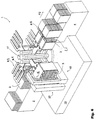
- FIG. 1 schematically shows an exemplary embodiment of the strapping device 1 according to the invention in a perspective view.
- a feed device 2 on which stacks 3 of printed products are fed in the direction of an arrow P1 of the strapping device 1 can be seen.
- the strapping device 1 has a substructure 10, a column 11 with, for example, four fork pairs (8.1 and 8.2 each) and a strapping position 13 in which a stack 3 is strapped.
- the column 11 is arranged to be rotatable step by step about an axis A perpendicular to the substructure 10 and is moved by a drive which is integrated in the substructure 10.
- the fork pairs each comprise a lower fork 8.1 and an upper fork 8.2, which are coupled to the column in the region of their proximal end.
- the upper forks 8.2 are individually displaceable along the column 11 for pressing the stacks and for handling stacks of different heights.
- the fork pairs and stacks pressed by them are moved by the column 11 step by step around the axis A.
- the fork pairs can be performed differently, respectively. can be shifted (eg linearly using link chains).
- a stack to be processed is fed by the feed device 2 between two assigned forks 8.1, 8.2 brought and pressed by lowering the upper fork 8.2 and held.
- the column 11 is held by rotating the column 11, for example by 90 ° Stack then brought into the strapping position 13.
- FIG. 2 shows the strapping device 1 from FIG. 1 without the feed device 2 and the removal device 4 in a perspective view.
- a stack 3 of printed products can be seen, which is held pressed between two forks 8.1 and 8.2 assigned to one another.
- the stack 3 is securely held and guided during the feeding to the strapping position 13, during the strapping in the strapping position and while leading away from the strapping position by the two forks 8.1 and 8.2 which are assigned to one another, as a result of which very high accelerations are possible.
- the strap guide means 16 which is used to create a strap loop for the strapping serves, is composed of different, partly stationary arranged in the strapping position 13, partly together with movable parts of the fork pairs.
- a stationary, lower one Channel part 16.1 arranged in which, for example, the means for tensioning, closing and separating (not shown) the strapping are integrated.
- a stationary, distal channel part 16.2 is arranged in the area of distal fork ends is also a stationary, distal channel part 16.2 is arranged is directed essentially vertically upwards from the lower channel part 16.1 except for one Height, which is greater than the highest position of the upper fork 8.2, and at which one connects upper, also stationary duct part 16.3.
- the upper channel part 16.3 extends over the upper fork 8.2 against the proximal end of the fork pair and connects to another, essentially vertical canal part (more proximal Channel part 16.4).
- This proximal channel part 16.4 is such on the lower fork 8.1 attached that it is aligned with the closed end of the slit-shaped opening is. From there it leads through the closed end of the slit-shaped opening of the upper one Fork 8.2, the upper fork 8.2 relative to this proximal channel part 16.4 is movable up and down.
- Each of the fork pairs has a proximal channel part 16.4 on.
- the band channel is equipped in a manner known to the person skilled in the art such that it the strapping can lead to the creation of the strap loop and that the strap pulled out of the channel over the entire length of the channel when tightening and can be positioned on the stack.
- can Parts of the band channel, in particular the proximal channel part 16.4 are also missing and can be the tape can be guided through loop areas without a guide channel by other means.
- the strapping can, for example, for self-guidance by means of profile rollers bent in its cross-section or profiled otherwise and thereby stiffened or it can be guided by air jets aligned in the direction of the belt.
- FIG. 3 shows a detailed view D from FIG. 2.
- Two forks 8.1, 8.2, which are assigned to one another, can be seen, the upper of which is mounted in a linear guide 20 on the column 11 so as to be displaceable up and down.
- the proximal channel part 16.4 is firmly connected to the lower fork 8.1, its opening being aligned with a slot-shaped opening 19.1 between two prongs 18 of the fork 8.1, in particular with the closed end of this opening 19.1.
- the proximal canal part 16.4 may continue below the lower fork in order to connect to the lower canal part 16.1.
- the proximal canal part 16.4 projects upward from the lower fork through a slit-shaped opening 19.2 aligned with the slit-shaped opening 19.1 between two prongs of the upper fork 8.2 and over the upper fork (in its highest position) such that it is in contact with the upper canal part 16.3 ( Figure 2) can connect.
- the upper fork 8.2 can be freely moved up and down relative to the proximal channel part 16.4.
- FIG. 4 shows schematically and by way of example another strapping device 1 in a perspective view.
- the strapping device 1 essentially corresponds to the system shown in FIG. 1, which is why the individual elements which have already been described in connection with FIG. 1 are identified by the same reference numerals and are no longer described.
- the strapping device 1 shown is also equipped as a wrapping device in that it has a wrapping position 22 in front of the strapping position 13 in the direction of movement of the stack 3.
- the wrapping position 22 for example, the following, known, serving the wrapping means are provided: a roll holder 23 for two rolls 24.1, 24.2 of a wrapping material 25 (for example made of polyethylene film) and means (26.1 and 26.2) for closing and separating the wrapping material 25 on the trailing stack side.
- the wrapping material 25 forms between the two rollers 24.1 and 24.2 a curtain extending over the path of movement of the stacks 3 held by the fork pairs, which is carried along by a conveyed stack 3, wraps around stack 3 and forks 8.1 and 8.2 and closes behind the stack an envelope is closed and separated from the rolls, such that it extends again for the next stack like a curtain over the path of movement.
- the strapping position 13 In the strapping position 13 they are already in connection with FIGS 3 described means for creating a strap, in particular parts of the Tape guide 16, means (not shown) for feeding the strapping tape 27 a tape roll and means (not shown) for tensioning, closing and separating of the strapping 27 is arranged.
- the one arranged stationary in the strapping position 13 Part of the tape guide 16 is for each strapping by one with the corresponding one Proximal channel part 16.4 fed to a pair of forks into a loop-shaped one Leadership supplemented.
- the strapping 27 is inserted into the channel so that it forms a loop around a stack.
- the supply roll for example, a tape storage device and a tape feed device to be provided, which are installed in the substructure 10, for example.
- FIG. 5 shows an enlarged detail A from FIG. 4.
- a stack 3 can be seen pressed between two forks 8.1 and 8.2 which are assigned to one another and which is strapped with a strapping band 27 and has previously been wrapped with a wrapping material 25.
- the strapping 27 lies in slot-like openings between the prongs 18 of the forks 8.1 and 8.2 closely against the stack 3, while the wrapping material also envelops the forks.
- bolts are inserted between the proximal ends of the prongs 18 such that they protrude from both forks and then moved against the proximal end of the prongs, thereby covering the and Push the strapped stack off the forks.
- FIG. 6 shows a further preferred embodiment of the strapping device 1 according to the invention in a perspective view.
- the strapping device 1 essentially corresponds to the device shown in FIG. 4, which is why the elements already described are no longer described.
- the wrapping position 22 and the strapping position 13 are identical, such that a stack 3 can be wrapped and strapped essentially simultaneously.
- a stack 3 to be strapped is gripped in a loading position in the area of the feed device 2 by a pair of forks 8.1, 8.2 and a wrapped and strapped stack 3 in a release position in the area of the removal device 4 is pushed by a pair of forks and led away.
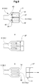
- FIGS. 7 and 8 show exemplary embodiments of the strap guide 16, which is to be provided for creating the strap loop in the strapping position 13 of the strapping device according to the invention.
- the figures are sections along the slit-shaped openings 19.1 and 19.2 of a pair of forks (8.1, 8.2) which holds a stack 3 pressed.
- the figures in the strap guide 16 also show the strap loop of the strapping 27 (as a dash-dotted line), a supply roll 28 from which the strapping is pulled, and schematically summarized as a box 29, the means for feeding the strapping 27 to the strap guide 16 and the means for Tightening / tensioning, closing and severing the strapping 27.
- FIG. 7 is essentially the same as in the figures 1 to 6, with a band channel completely defining the band loop consisting of a stationary lower, distal and upper channel part (16.1, 16.2 and 16.3) and with one with the fork pair 8.1 and 8.2 in the strapping position moved proximal canal part 16.4, which extends through the closed ends the slot-shaped openings 19.1 and 19.2 in the forks 8.1 and 8.2 continues.
- the upper channel part 16.3 are moved with the forks 8.1 and 8.2, so that the boundary between the stationary duct part and the moving duct part at the 17 designated place.
- the upper channel part can also be in the upper one Press arm 8.2 can be integrated.
- Figure 8 shows an embodiment of tape guides 16, in which only over and under the forks 8.1 and 8.2 a channel part (lower and upper channel part 16.1 and 16.3) is provided while the distal and proximal canal part is missing.
- a channel part lower and upper channel part 16.1 and 16.3
- the distal and proximal canal part is missing.
- For one problem-free creation of a tape loop are for the areas without tape channel to provide other management means. These are at least collecting funnels 18 to the the ends of the existing duct parts and / or nozzles to catch the band end Generation of air jets that sweep the strapping across the channelless areas to lead.
- the strapping can also be done by a Appropriate profiling can be stiffened in order to easily run over the guide Areas to be moved.
- the embodiment according to FIG. 8 has the advantage that in the strapping position both the distal and the proximal side of the stack remain accessible, for example for means with which parts of the wrapping protruding from the stack sides can be pulled over these sides and closed around the stack.
- the two press arms or press forks 8.1 and 8.2 the stack from below and above and becomes the upper press arm for pressing one Stack and its delivery and reception against and from the lower press arm moves away (up and down) while the lower press arm is a non-varying one Height. All this is not a requirement for the invention.
- the press arms always press the stack from its end faces, but these can have a position in space.
- the press arms are movable relative to one another. there it is advantageous to always close the one of the press arms in the strapping position position and especially the means for tightening / tightening, closing and severing the strapping on the outside of the so positioned Arrange press arm, as is the case in Figures 7 and 8.
- FIG. 9 shows how the method according to the invention is advantageous for creating a Cross strapping around a stack held between press arms, which if necessary is also encased, can be added.
- the stack 3, as shown above in FIG. 9 is, as already described, held pressed by press arms 8.1 and 8.2, wrapped with a wrapping material 25 and with a strapping 27 straps, the wrapping including the press arms and the strapping is arranged above the envelope, is directed transversely to the envelope and in slot-shaped Openings 19.1 and 19.2 of the press arms 8.1 and 8.2 run. That stack with wrapping and strapping is now closed by means of bolts 40 which Inserted ends of further slot-shaped openings 19 'and against the distal End of the press arms are moved, pushed by the press arms.
- the stack is only pushed halfway from the press arms and thus in positioned another strapping position. In this position he becomes in itself known manner transversely to the direction of ejection with another strapping 27 ' strapped.
- the strapping 27 ' has been created, the ejection bolts 40 become wider moved and the stack 3 is pushed completely from the press arms.
- the second strapping can be done with the fork pair in the same position to be created.
- it is in another, on the strapping position created the following discharge position.
- the strap guide for such strapping advantageously has the outside of the lower press arm on a corresponding opening in the Press arm aligned, stationary channel part and one in the upper press arm integrated duct part.
Landscapes
- Engineering & Computer Science (AREA)
- Mechanical Engineering (AREA)
- Basic Packing Technique (AREA)
- Auxiliary Devices For And Details Of Packaging Control (AREA)
Abstract
Description
- Figur 1
- zeigt schematisch eine beispielhafte Ausführungsform der erfindungsgemässen Umreifungsvorrichtung in einer perspektivischen Ansicht;
- Figur 2
- zeigt einen Teil der Umreifungsvorrichtung aus Figur 1 in einer perspektivischen Ansicht;
- Figur 3
- zeigt die Pressarme und einen Teil der Bandführungen der Umreifungsvorrichtung gemäss Figuren 1 und 2;
- Figur 4
- zeigt eine weitere Ausführungsform der erfindungsgemässen Umreifungsvorrichtung mit einer Umhüllungsposition und einer Umreifungsposition;
- Figur 5
- zeigt einen in der Vorrichtung gemäss Figur 4 umhüllten und umreiften Stapel unmittelbar nach der Umreifung;
- Figur 6
- zeigt eine weitere Ausführungsform der erfindungsgemässen Umreifungsvorrichtung mit einer Umreifungsposition, die gleichzeitig Umhüllungsposition ist;
- Figuren 7 und 8
- zeigen im Schnitt durch die Umreifüngsposition verschiedene Ausführungsformen von Bandführungsmitteln;
- Figur 9
- zeigt eine weitere Umreifüng eines nach dem erfindungsgemässen Verfahren umreiften Stapels.
Claims (19)
- Verfahren zum sequentiellen Umreifen von Druckproduktestapeln (3) mit zwei einander gegenüberliegenden Stapelstimseiten, insbesondere von derartigen Stapeln mit verschiedenen Stapelhöhen, wobei die Stapel (3) nacheinander einer Umreifungsposition (13) zugeführt, in der Umreifungsposition (13) umreift und dann aus der Umreifungsposition (13) weggeführt werden und wobei in der Umreifungsposition (13) ein Umreifungsband (27) in einer Schlaufe um den Stapel (3) gelegt und dann um den Stapel (3) festgezogen und geschlossen wird, dadurch gekennzeichnet, dass jeder Stapel (3) mindestens für die Zuführung und Umreifung zwischen zwei an den Stapelstirnseiten angreifenden Pressarmen (8.1 und 8.2) mit je mindestens einer schlitzförmigen Öffnung (19.1, 19.2) gepresst gehalten wird, dass die Schlaufe des Umreifungsbandes (27) im Bereiche der Stapelstirnseiten ausserhalb der Pressarme (8.1, 8.2) und auf die schlitzförmigen Öffnungen (19.1, 19.2) ausgerichtet angelegt wird und dass das Umreifungsband (27) beim Festziehen durch die schlitzförmigen Öffnungen (19.1, 19.2) gezogen und auf dem Stapel (3) positioniert wird.
- Verfahren nach Anspruch 1, dadurch gekennzeichnet, dass bei der Zuführung eines Stapels (3) zur Umreifungsposition (13) mindestens ein Teil von Bandführungen (16) für das Anlegen der Schlaufe des Umreifungsbandes (27) mit dem Stapel (3) und den Pressarmen (8.1 und 8.2) in die Umreifungsposition (13) bewegt wird.
- Verfahren nach Anspruch 1 oder 2, dadurch gekennzeichnet, dass die Pressarme (8.1, 8.2) aufeinander ausgerichtete distale und proximale Enden aufweisen, wobei sie an ihren proximalen Enden an einem Antrieb angekoppelt sind und ihre distalen Enden gabelförmig mit mindestens je zwei Zinken (18) und mindestens einer schlitzförmigen Öffnung (19.1, 19.2) zwischen zwei Zinken (18) ausgestaltet sind und wobei sie für die Zuführung in einer Zuführungsrichtung verschoben werden, die im wesentlichen quer zu einer Verbindung zwischen distalen und proximalen Pressarmenden ausgerichtet ist, und die Schlaufe des Umreifungsbandes (27) in einer Ebene angelegt wird, die parallel zur genannten Verbindung ausgerichtet ist.
- Verfahren nach Anspruch 3, dadurch gekennzeichnet, dass die Stapel (3) zusätzlich auch quer zur genannten Umreifung umreift werden.
- Verfahren nach Anspruch 3, dadurch gekennzeichnet, dass der Stapel (3) zusätzlich zur Umreifung mit einem Umhüllungsmaterial (25) umhüllt wird, wobei das Umhüllungsmaterial (25) vor der Umreifung um die Pressarme (8.1, 8.2) und den Stapel (3) gelegt wird in einer Richtung quer zur Schlaufe des Umreifungsbandes (27) und derart, dass die Umreifüng ausserhalb des Umhüllungsmaterials positioniert wird, dass das Umhüllungsmaterial (25) um den Stapel (3) und die Pressarme (8.1, 8.2) geschlossen wird und dass dann der umhüllte und umreifte Stapel (3) durch eine Relativbewegung zu den Pressarmen (8.1, 8.2) von diesen entfernt wird.
- Verfahren nach Anspruch 5, dadurch gekennzeichnet, dass die Pressarme (8.1, 8.2) mit dem Stapel (3) zum Umlegen des Umhüllungsmaterials (25) durch einen Vorhang des Umhüllungsmaterials (25) bewegt werden.
- Verfahren nach Anspruch 6, dadurch gekennzeichnet, dass das Umhüllungsmaterial (25) während der Umreifung um Pressarme (8.1, 8.2) und Stapel (3) geschlossen wird.
- Verfahren nach einem der Ansprüche 5 bis 7, dadurch gekennzeichnet, dass der umhüllte und umreifte Stapel (3) durch eine Relativbewegung zwischen Pressarmen (8.1, 8.2) und Stapel (3) in der Richtung der Verbindung zwischen proximalen und distalen Pressarmenden von den Pressarmen (8.1, 8.2) getrennt wird.
- Verfahren nach Anspruch 8, dadurch gekennzeichnet, dass der umhüllte und umreifte Stapel (3) halbwegs von den Pressarmen (8.1, 8.2) getrennt wird, dann zusätzlich quer zur Richtung der Relativbewegung umreift wird und dann vollständig von den Pressarmen (8.1, 8.2) getrennt wird.
- Vorrichtung zum sequentiellen Umreifen von Druckproduktestapeln (3) mit zwei einander gegenüberliegenden Stirnseiten, welche Vorrichtung eine Umreifungsposition (13) mit einer Bandführung (16) zur Erstellung einer Bandschlaufe um einen in der Umreifungsposition (13) positionierten Stapel (3) und Mitteln (29) zur Zuführung eines Umreifungsbandes (27) in die Bandführung (16) und zum Festziehen, Spannen, Verschliessen und Abtrennen des Umreifungsbandes (27) sowie Mittel zur Zuführung der Stapel (3) in die Umreifungsposition (13) und zum Wegführen der Stapel (3) aus der Umreifungsposition (13) aufweist, dadurch gekennzeichnet, dass die Mittel zum Zuführen und Wegführen Paare von gegeneinander bewegbaren Pressarmen (8.1, 8.2) aufweisen, mit denen Stapel zwischen ihren Stirnseiten pressbar sind, welche Pressarme (8.1, 8.2) je mindestens eine schlitzförmige Öffnung (19.1, 19.2) aufweisen, und dass die Bandführung (16) im Bereich der Stapelstirnseiten ausserhalb der Pressarme (8.1, 8.2) eines in der Umreifungsposition (13) positionierten Pressarmpaares angeordnet sind und auf die schlitzförmigen Öffnungen (19.1, 19.2) der Pressarme (8.1, 8.2) ausgerichtet sind.
- Vorrichtung nach Anspruch 10, dadurch gekennzeichnet, dass mindestens ein Teil der Bandführung (16) Bandkanäle sind.
- Vorrichtung nach Anspruch 11, dadurch gekennzeichnet, dass die Bandführung (16) zusätzlich zu Bandkanalteilen (16.1, 16.3) Mittel zum Profilieren des Querschnittes des Umreifungsbandes (27) oder Mittel zur Erzeugung von das Umreifungsband (27) führenden Luftstrahlen aufweist.
- Vorrichtung nach Anspruch 11, dadurch gekennzeichnet, dass mindestens ein Bandkanalteil (16.4) mit den Pressarmen (8.1, 8.2) verbunden ist und mit den Pressarmen (8.1, 8.2) in der Umreifungsposition (13) positioniert wird.
- Vorrichtung nach einem der Ansprüche 10 bis 13, dadurch gekennzeichnet, dass die Pressarme (8.1, 8.2) aufeinander ausgerichtete distale und proximale Enden aufweisen, wobei sie an ihren proximalen Enden an einem Antrieb angekoppelt sind und ihre distalen Enden gabelförmig mit mindestens je zwei Zinken (18) und mindestens einer schlitzförmigen Öffnung (19.1, 19.2) zwischen zwei Zinken (18) ausgestaltet sind.
- Vorrichtung nach Anspruch 14, dadurch gekennzeichnet, dass die Pressarme (8.1, 8.2) zusätzlich quer zu den schlitzförmigen Öffnungen (19.1, 19.2) verlaufende, weitere Öffnungen oder in den Pressarmen integrierte Bandkanalteile aufweisen.
- Vorrichtung nach Anspruch 14, dadurch gekennzeichnet, dass sie zusätzlich Mittel zum Umhüllen von Stapeln (3) mit einem Umhüllungsmaterial (25) aufweist.
- Vorrichtung nach Anspruch 16, dadurch gekennzeichnet, dass die Mittel zur Umhüllung in einer der Umreifungsposition (13) vorgeschalteten Umhüllungsposition (22) angeordnet sind oder in der Umreifungsposition (13).
- Vorrichtung nach Anspruch 16 oder 17, dadurch gekennzeichnet, dass die Mittel zur Umhüllung Mittel aufweisen, mit denen ein sich über den Zuführungsweg der Pressarme (8.1, 8.2) und Stapel (3) zur Umreifungsposition (13) erstreckender Vorhang des Umhüllungsmaterials (25) erstellbar ist.
- Vorrichtung nach einem der Ansprüche 14 bis 18, dadurch gekennzeichnet, dass sie weitere Mittel zur weiteren Umreifung (27') der Stapel (3) aufweist, in deren Bereich die distalen Enden der Pressarme (8.1, 8.2) positionierbar sind, derart, dass ein von den Pressarmen gepresst gehaltener Stapel (3) halbwegs über das distale Ende der Pressarme (8.1, 8.1) geschoben und dann quer zur Schieberichtung umreift werden kann.
Applications Claiming Priority (2)
| Application Number | Priority Date | Filing Date | Title |
|---|---|---|---|
| CH16872000 | 2000-08-30 | ||
| CH16872000 | 2000-08-30 |
Publications (2)
| Publication Number | Publication Date |
|---|---|
| EP1184283A1 true EP1184283A1 (de) | 2002-03-06 |
| EP1184283B1 EP1184283B1 (de) | 2004-10-20 |
Family
ID=4565902
Family Applications (1)
| Application Number | Title | Priority Date | Filing Date |
|---|---|---|---|
| EP01810800A Expired - Lifetime EP1184283B1 (de) | 2000-08-30 | 2001-08-20 | Verfahren und Vorrichtung zur Umreifung von Stapeln von Druckereierzeugnissen |
Country Status (6)
| Country | Link |
|---|---|
| US (1) | US6619014B2 (de) |
| EP (1) | EP1184283B1 (de) |
| AT (1) | ATE280086T1 (de) |
| CA (1) | CA2356518A1 (de) |
| DE (1) | DE50104188D1 (de) |
| DK (1) | DK1184283T3 (de) |
Cited By (3)
| Publication number | Priority date | Publication date | Assignee | Title |
|---|---|---|---|---|
| CN104290955A (zh) * | 2013-07-16 | 2015-01-21 | 聚龙股份有限公司 | 一种自动扎把机 |
| DE102015012484A1 (de) | 2015-09-24 | 2017-03-30 | Giesecke & Devrient Gmbh | Banderolierung von Banknoten |
| JP2019006495A (ja) * | 2017-06-28 | 2019-01-17 | ニシハツ産業株式会社 | 紙を巻いた積層平海苔束の製造方法及び製造装置 |
Families Citing this family (21)
| Publication number | Priority date | Publication date | Assignee | Title |
|---|---|---|---|---|
| JP4542717B2 (ja) * | 2001-01-12 | 2010-09-15 | 富士フイルム株式会社 | シート集積体生産システム |
| ITBO20040253A1 (it) * | 2004-04-23 | 2004-07-23 | Aetna Group Spa | Macchina per il confezionamento di gruppi di prodotti mediante spezzoni tubolari di film elastico |
| US7789226B2 (en) * | 2004-09-13 | 2010-09-07 | Meadwestvaco Corporation | Packaged banded envelopes |
| CA2579730C (en) * | 2004-09-13 | 2010-04-13 | Meadwestvaco Corporation | Banded envelopes and method for assembling a package of banded envelopes |
| US7849770B2 (en) * | 2004-10-07 | 2010-12-14 | Douglas Machine, Inc. | Film cutter |
| US20060075861A1 (en) * | 2004-10-07 | 2006-04-13 | Flooding Daniel L | Film cutter |
| US7584589B2 (en) * | 2007-03-09 | 2009-09-08 | Georgia-Pacific Consumer Products Lp | Robotic multi-product case-packing system |
| JP5198102B2 (ja) * | 2007-03-30 | 2013-05-15 | 株式会社東芝 | 紙葉類処理システム |
| US7856797B2 (en) * | 2008-04-03 | 2010-12-28 | Arm Automation, Inc. | Automated collector device and methods |
| EP2189407A1 (de) * | 2008-11-21 | 2010-05-26 | Kba-Giori S.A. | Verfahren und System zur Verarbeitung von bedruckten Blättern, insbesondere Blätter mit gedruckten Sicherheiten als individuelle Dokumente |
| JP5433680B2 (ja) * | 2009-03-10 | 2014-03-05 | グローリー株式会社 | 紙幣結束装置及び紙幣結束方法 |
| CN102320388B (zh) * | 2011-09-06 | 2012-09-12 | 北京华夏聚龙自动化股份公司 | 一种纸币打捆机 |
| CN102442559B (zh) * | 2011-09-21 | 2015-04-15 | 广州广电运通金融电子股份有限公司 | 薄片类介质整叠捆扎装置及自助服务设备 |
| EP2615036B1 (de) * | 2012-01-16 | 2014-11-12 | Kabushiki Kaisha Toshiba | Stapel-/Einschlagvorrichtung |
| ES2415986B1 (es) * | 2013-02-07 | 2014-05-27 | Global Hub Services, S.L. | Máquina plegadora enfajadora de ristras de sobres flexibles |
| USD726954S1 (en) * | 2014-08-05 | 2015-04-14 | General Luminaire Co., Ltd. | Hexagonal lamp panel |
| WO2017041007A1 (en) | 2015-09-04 | 2017-03-09 | Douglas Machine Inc. | Improved robotic article handling system & operations |
| CN107284728B (zh) * | 2017-07-25 | 2020-03-24 | 昆明瑞丰印刷有限公司 | 一种烟标压合捆扎装置 |
| US11214390B2 (en) | 2018-04-23 | 2022-01-04 | R.A Jones & Co. | Pouch containment and carton loading |
| CN112265706A (zh) * | 2020-11-07 | 2021-01-26 | 常德长岭机械制造科技有限公司 | 一种手帕纸打包用具有压实机构的打包装置 |
| CN117416555A (zh) * | 2023-09-21 | 2024-01-19 | 广东智汇名远智能装备有限公司 | 一种包装方法及其包装设备 |
Citations (3)
| Publication number | Priority date | Publication date | Assignee | Title |
|---|---|---|---|---|
| DE3248788A1 (de) | 1981-12-30 | 1983-07-14 | Metaverpa B.V., 3738 Maartensdijk | Vorrichtung zum drehen eines gegenstandes um einen gegebenen winkel um eine vertikale achse |
| US4870807A (en) * | 1987-02-18 | 1989-10-03 | Palamides Gmbh | Method and apparatus for packaging printed matter |
| WO2000034127A1 (de) | 1998-12-07 | 2000-06-15 | Ferag Ag | Verfahren und vorrichtung zur schutzumhüllung von stapeln von druckereierzeugnissen |
Family Cites Families (11)
| Publication number | Priority date | Publication date | Assignee | Title |
|---|---|---|---|---|
| US3914918A (en) * | 1973-11-08 | 1975-10-28 | Hartford Fibres Ltd | Method of packaging flock fibres |
| CH588380A5 (de) * | 1975-02-25 | 1977-05-31 | Hunkeler Jos Ag Fabrik Fuer Gr | |
| JPS5786432A (en) * | 1980-11-11 | 1982-05-29 | Tokyo Shibaura Electric Co | Bundling device |
| US4712354A (en) * | 1984-02-23 | 1987-12-15 | Lantech, Inc. | Dual rotating stretch wrapping apparatus and process |
| US4828645A (en) * | 1987-11-25 | 1989-05-09 | Xerox Corporation | Binding apparatus |
| EP0420560B1 (de) * | 1989-09-29 | 1993-11-18 | Glory Kogyo Kabushiki Kaisha | Vorrichtung zum Bündeln von Papierblättern |
| US5692999A (en) * | 1992-02-06 | 1997-12-02 | Roll Systems, Inc. | Method and apparatus for business forms processing |
| US5299410A (en) * | 1992-11-05 | 1994-04-05 | Gunther International, Ltd. | Packaging mechanism and method |
| US5472540A (en) * | 1994-02-02 | 1995-12-05 | Marquip, Inc. | Method and apparatus for making pallet supports and pallets incorporating said supports |
| DE4416013A1 (de) * | 1994-05-06 | 1995-11-09 | Georg Lang | Vorrichtung zum Umreifen eines Packgutes |
| DE19722066A1 (de) * | 1997-05-27 | 1998-12-03 | Smb Schwede Maschinenbau Gmbh | Umreifungsmaschine zum Umreifen von Objekten mit einer objekthöhenabhängigen Rückspanneinrichtung |
-
2001
- 2001-08-20 DE DE50104188T patent/DE50104188D1/de not_active Expired - Lifetime
- 2001-08-20 AT AT01810800T patent/ATE280086T1/de not_active IP Right Cessation
- 2001-08-20 EP EP01810800A patent/EP1184283B1/de not_active Expired - Lifetime
- 2001-08-20 DK DK01810800T patent/DK1184283T3/da active
- 2001-08-29 US US09/942,346 patent/US6619014B2/en not_active Expired - Fee Related
- 2001-08-30 CA CA002356518A patent/CA2356518A1/en not_active Abandoned
Patent Citations (3)
| Publication number | Priority date | Publication date | Assignee | Title |
|---|---|---|---|---|
| DE3248788A1 (de) | 1981-12-30 | 1983-07-14 | Metaverpa B.V., 3738 Maartensdijk | Vorrichtung zum drehen eines gegenstandes um einen gegebenen winkel um eine vertikale achse |
| US4870807A (en) * | 1987-02-18 | 1989-10-03 | Palamides Gmbh | Method and apparatus for packaging printed matter |
| WO2000034127A1 (de) | 1998-12-07 | 2000-06-15 | Ferag Ag | Verfahren und vorrichtung zur schutzumhüllung von stapeln von druckereierzeugnissen |
Cited By (4)
| Publication number | Priority date | Publication date | Assignee | Title |
|---|---|---|---|---|
| CN104290955A (zh) * | 2013-07-16 | 2015-01-21 | 聚龙股份有限公司 | 一种自动扎把机 |
| CN104290955B (zh) * | 2013-07-16 | 2016-08-17 | 聚龙股份有限公司 | 一种自动扎把机 |
| DE102015012484A1 (de) | 2015-09-24 | 2017-03-30 | Giesecke & Devrient Gmbh | Banderolierung von Banknoten |
| JP2019006495A (ja) * | 2017-06-28 | 2019-01-17 | ニシハツ産業株式会社 | 紙を巻いた積層平海苔束の製造方法及び製造装置 |
Also Published As
| Publication number | Publication date |
|---|---|
| US20020073651A1 (en) | 2002-06-20 |
| ATE280086T1 (de) | 2004-11-15 |
| DK1184283T3 (da) | 2005-01-24 |
| CA2356518A1 (en) | 2002-02-28 |
| EP1184283B1 (de) | 2004-10-20 |
| US6619014B2 (en) | 2003-09-16 |
| DE50104188D1 (de) | 2004-11-25 |
Similar Documents
| Publication | Publication Date | Title |
|---|---|---|
| EP1184283B1 (de) | Verfahren und Vorrichtung zur Umreifung von Stapeln von Druckereierzeugnissen | |
| EP0894721B1 (de) | Verfahren und Vorrichtung zum Umreifen von einzelnen Gegenständen oder von Stapeln von Gegenständen | |
| EP0968919B1 (de) | Vorrichtung zum Umwickeln von quaderförmigen Gegenständen mit einem Bahnförmigen Umwickelmaterial | |
| EP0120251A1 (de) | Verfahren und Vorrichtung zum Umwickeln von vorzugsweise quaderförmigen Gegenständen mit einem bahnförmigen Umwickelmaterial | |
| DE60104059T2 (de) | Vorrichtung zum Anbringen eines Eckschutzes auf einer Ecke einer Verpackung und System zum Schutz einer Verpackung | |
| EP3431399A1 (de) | Vorrichtung und verfahren zum verpacken gestapelter länglicher gegenstände sowie verwendung einer derartigen vorrichtung | |
| EP0890509A1 (de) | Verfahren und Vorrichtung zum Umreifen von einzelnen Gegenständen oder von Stapeln von Gegenständen. | |
| DE2615560A1 (de) | Maschine zum aufreihen verschiedenartiger bauelemente | |
| DE3338036C2 (de) | Vorrichtung zum Umwickeln von Packstücken oder Gebinden in einer Stretchfolie | |
| CH700153A1 (de) | Umreifungsvorrichtung und Verfahren zum Betrieb davon. | |
| DE19920531C2 (de) | Verpackungsstraße für Zeitschriften, Magazine und dergleichen Druckprodukte | |
| EP1568638B1 (de) | Vorrichtung zum Banderolieren von Stapeln flächiger Werkstücke | |
| EP1401710B1 (de) | Knoterhaken und damit ausgerüsteter garnknoter | |
| EP1517836B1 (de) | Umreifungsvorrichtung | |
| EP0432592A1 (de) | Vorrichtung zum Verpacken von Zigaretten | |
| EP0618138B1 (de) | Einrichtung zum Herstellen von tragbaren, rohrartigen Paketen aus Druckereiprodukten | |
| EP1140630A1 (de) | Verfahren und vorrichtung zur schutzumhüllung von stapeln von druckereierzeugnissen | |
| EP0618139A1 (de) | Verfahren und Vorrichtung zum Bearbeiten von Druckereiprodukten | |
| WO2003000035A1 (de) | Garnknoter | |
| EP1050463B1 (de) | Umreifungsmaschine zum Umreifen eines Gutstapels | |
| DE3608250A1 (de) | Vorrichtung zum zufuehren von verpackungsmitteln zu packmaschinen | |
| DE2904554A1 (de) | Verfahren zum einlegen von flossenpackungen in einen behaelter und einrichtung zur durchfuehrung des verfahrens | |
| DE19821918B4 (de) | Verfahren zum Fördern von Produkten und Handhabungseinheit zur Durchführung des Verfahrens | |
| DE19623951C1 (de) | Vorrichtung zum Falten und Einbringen eines Beipackzettels | |
| DE2060753C2 (de) | Vorrichtung zum Umschlingen von Verpackungsgut |
Legal Events
| Date | Code | Title | Description |
|---|---|---|---|
| PUAI | Public reference made under article 153(3) epc to a published international application that has entered the european phase |
Free format text: ORIGINAL CODE: 0009012 |
|
| AK | Designated contracting states |
Kind code of ref document: A1 Designated state(s): AT BE CH CY DE DK ES FI FR GB GR IE IT LI LU MC NL PT SE TR |
|
| AX | Request for extension of the european patent |
Free format text: AL;LT;LV;MK;RO;SI |
|
| 17P | Request for examination filed |
Effective date: 20020607 |
|
| AKX | Designation fees paid |
Free format text: AT BE CH CY DE DK ES FI FR GB GR IE IT LI LU MC NL PT SE TR |
|
| 17Q | First examination report despatched |
Effective date: 20030630 |
|
| GRAP | Despatch of communication of intention to grant a patent |
Free format text: ORIGINAL CODE: EPIDOSNIGR1 |
|
| GRAS | Grant fee paid |
Free format text: ORIGINAL CODE: EPIDOSNIGR3 |
|
| GRAA | (expected) grant |
Free format text: ORIGINAL CODE: 0009210 |
|
| AK | Designated contracting states |
Kind code of ref document: B1 Designated state(s): AT BE CH CY DE DK ES FI FR GB GR IE IT LI LU MC NL PT SE TR |
|
| PG25 | Lapsed in a contracting state [announced via postgrant information from national office to epo] |
Ref country code: IT Free format text: LAPSE BECAUSE OF FAILURE TO SUBMIT A TRANSLATION OF THE DESCRIPTION OR TO PAY THE FEE WITHIN THE PRE;WARNING: LAPSES OF ITALIAN PATENTS WITH EFFECTIVE DATE BEFORE 2007 MAY HAVE OCCURRED AT ANY TIME BEFORE 2007. THE CORRECT EFFECTIVE DATE MAY BE DIFFERENT FROM THE ONE RECORDED.SCRIBED TIME-LIMIT Effective date: 20041020 Ref country code: NL Free format text: LAPSE BECAUSE OF FAILURE TO SUBMIT A TRANSLATION OF THE DESCRIPTION OR TO PAY THE FEE WITHIN THE PRESCRIBED TIME-LIMIT Effective date: 20041020 Ref country code: FI Free format text: LAPSE BECAUSE OF FAILURE TO SUBMIT A TRANSLATION OF THE DESCRIPTION OR TO PAY THE FEE WITHIN THE PRESCRIBED TIME-LIMIT Effective date: 20041020 Ref country code: FR Free format text: LAPSE BECAUSE OF FAILURE TO SUBMIT A TRANSLATION OF THE DESCRIPTION OR TO PAY THE FEE WITHIN THE PRESCRIBED TIME-LIMIT Effective date: 20041020 Ref country code: TR Free format text: LAPSE BECAUSE OF FAILURE TO SUBMIT A TRANSLATION OF THE DESCRIPTION OR TO PAY THE FEE WITHIN THE PRESCRIBED TIME-LIMIT Effective date: 20041020 Ref country code: IE Free format text: LAPSE BECAUSE OF FAILURE TO SUBMIT A TRANSLATION OF THE DESCRIPTION OR TO PAY THE FEE WITHIN THE PRESCRIBED TIME-LIMIT Effective date: 20041020 |
|
| REG | Reference to a national code |
Ref country code: GB Ref legal event code: FG4D Free format text: NOT ENGLISH |
|
| REG | Reference to a national code |
Ref country code: CH Ref legal event code: EP |
|
| REG | Reference to a national code |
Ref country code: IE Ref legal event code: FG4D Free format text: GERMAN |
|
| REF | Corresponds to: |
Ref document number: 50104188 Country of ref document: DE Date of ref document: 20041125 Kind code of ref document: P |
|
| REG | Reference to a national code |
Ref country code: CH Ref legal event code: NV Representative=s name: FREI PATENTANWALTSBUERO |
|
| PG25 | Lapsed in a contracting state [announced via postgrant information from national office to epo] |
Ref country code: GR Free format text: LAPSE BECAUSE OF FAILURE TO SUBMIT A TRANSLATION OF THE DESCRIPTION OR TO PAY THE FEE WITHIN THE PRESCRIBED TIME-LIMIT Effective date: 20050120 |
|
| REG | Reference to a national code |
Ref country code: DK Ref legal event code: T3 |
|
| PG25 | Lapsed in a contracting state [announced via postgrant information from national office to epo] |
Ref country code: ES Free format text: LAPSE BECAUSE OF FAILURE TO SUBMIT A TRANSLATION OF THE DESCRIPTION OR TO PAY THE FEE WITHIN THE PRESCRIBED TIME-LIMIT Effective date: 20050131 |
|
| REG | Reference to a national code |
Ref country code: SE Ref legal event code: TRGR |
|
| GBT | Gb: translation of ep patent filed (gb section 77(6)(a)/1977) |
Effective date: 20050119 |
|
| NLV1 | Nl: lapsed or annulled due to failure to fulfill the requirements of art. 29p and 29m of the patents act | ||
| REG | Reference to a national code |
Ref country code: IE Ref legal event code: FD4D |
|
| PG25 | Lapsed in a contracting state [announced via postgrant information from national office to epo] |
Ref country code: LU Free format text: LAPSE BECAUSE OF NON-PAYMENT OF DUE FEES Effective date: 20050820 Ref country code: CY Free format text: LAPSE BECAUSE OF FAILURE TO SUBMIT A TRANSLATION OF THE DESCRIPTION OR TO PAY THE FEE WITHIN THE PRESCRIBED TIME-LIMIT Effective date: 20050820 Ref country code: AT Free format text: LAPSE BECAUSE OF NON-PAYMENT OF DUE FEES Effective date: 20050820 |
|
| PLBE | No opposition filed within time limit |
Free format text: ORIGINAL CODE: 0009261 |
|
| STAA | Information on the status of an ep patent application or granted ep patent |
Free format text: STATUS: NO OPPOSITION FILED WITHIN TIME LIMIT |
|
| PG25 | Lapsed in a contracting state [announced via postgrant information from national office to epo] |
Ref country code: MC Free format text: LAPSE BECAUSE OF NON-PAYMENT OF DUE FEES Effective date: 20050831 Ref country code: BE Free format text: LAPSE BECAUSE OF NON-PAYMENT OF DUE FEES Effective date: 20050831 |
|
| 26N | No opposition filed |
Effective date: 20050721 |
|
| EN | Fr: translation not filed | ||
| BERE | Be: lapsed |
Owner name: *FERAG A.G. Effective date: 20050831 |
|
| PG25 | Lapsed in a contracting state [announced via postgrant information from national office to epo] |
Ref country code: PT Free format text: LAPSE BECAUSE OF NON-PAYMENT OF DUE FEES Effective date: 20050320 |
|
| PGFP | Annual fee paid to national office [announced via postgrant information from national office to epo] |
Ref country code: GB Payment date: 20070823 Year of fee payment: 7 |
|
| GBPC | Gb: european patent ceased through non-payment of renewal fee |
Effective date: 20080820 |
|
| PG25 | Lapsed in a contracting state [announced via postgrant information from national office to epo] |
Ref country code: GB Free format text: LAPSE BECAUSE OF NON-PAYMENT OF DUE FEES Effective date: 20080820 |
|
| PGFP | Annual fee paid to national office [announced via postgrant information from national office to epo] |
Ref country code: DK Payment date: 20140820 Year of fee payment: 14 Ref country code: DE Payment date: 20140821 Year of fee payment: 14 |
|
| PGFP | Annual fee paid to national office [announced via postgrant information from national office to epo] |
Ref country code: SE Payment date: 20140820 Year of fee payment: 14 |
|
| PGFP | Annual fee paid to national office [announced via postgrant information from national office to epo] |
Ref country code: CH Payment date: 20141029 Year of fee payment: 14 |
|
| REG | Reference to a national code |
Ref country code: DE Ref legal event code: R082 Ref document number: 50104188 Country of ref document: DE Representative=s name: PATENTANWAELTE UND RECHTSANWALT DR. WEISS, ARA, DE Ref country code: DE Ref legal event code: R082 Ref document number: 50104188 Country of ref document: DE Representative=s name: PATENTANWAELTE UND RECHTSANWALT WEISS, ARAT & , DE |
|
| REG | Reference to a national code |
Ref country code: DE Ref legal event code: R119 Ref document number: 50104188 Country of ref document: DE |
|
| REG | Reference to a national code |
Ref country code: DK Ref legal event code: EBP Effective date: 20150831 |
|
| REG | Reference to a national code |
Ref country code: SE Ref legal event code: EUG |
|
| REG | Reference to a national code |
Ref country code: CH Ref legal event code: PL |
|
| PG25 | Lapsed in a contracting state [announced via postgrant information from national office to epo] |
Ref country code: CH Free format text: LAPSE BECAUSE OF NON-PAYMENT OF DUE FEES Effective date: 20150831 Ref country code: LI Free format text: LAPSE BECAUSE OF NON-PAYMENT OF DUE FEES Effective date: 20150831 |
|
| PG25 | Lapsed in a contracting state [announced via postgrant information from national office to epo] |
Ref country code: SE Free format text: LAPSE BECAUSE OF NON-PAYMENT OF DUE FEES Effective date: 20150821 |
|
| PG25 | Lapsed in a contracting state [announced via postgrant information from national office to epo] |
Ref country code: DE Free format text: LAPSE BECAUSE OF NON-PAYMENT OF DUE FEES Effective date: 20160301 |
|
| PG25 | Lapsed in a contracting state [announced via postgrant information from national office to epo] |
Ref country code: DK Free format text: LAPSE BECAUSE OF NON-PAYMENT OF DUE FEES Effective date: 20150831 |