EP1181617B1 - Systeme de projection reflecteur a affichage couleur liquide utilisant un diviseur optique de faisceau de polarisation a grand angle - Google Patents
Systeme de projection reflecteur a affichage couleur liquide utilisant un diviseur optique de faisceau de polarisation a grand angle Download PDFInfo
- Publication number
- EP1181617B1 EP1181617B1 EP00936012A EP00936012A EP1181617B1 EP 1181617 B1 EP1181617 B1 EP 1181617B1 EP 00936012 A EP00936012 A EP 00936012A EP 00936012 A EP00936012 A EP 00936012A EP 1181617 B1 EP1181617 B1 EP 1181617B1
- Authority
- EP
- European Patent Office
- Prior art keywords
- light
- pbs
- optical imaging
- imaging system
- polarization
- Prior art date
- Legal status (The legal status is an assumption and is not a legal conclusion. Google has not performed a legal analysis and makes no representation as to the accuracy of the status listed.)
- Expired - Lifetime
Links
Images


Classifications
-
- G—PHYSICS
- G02—OPTICS
- G02B—OPTICAL ELEMENTS, SYSTEMS OR APPARATUS
- G02B27/00—Optical systems or apparatus not provided for by any of the groups G02B1/00 - G02B26/00, G02B30/00
- G02B27/10—Beam splitting or combining systems
- G02B27/14—Beam splitting or combining systems operating by reflection only
- G02B27/149—Beam splitting or combining systems operating by reflection only using crossed beamsplitting surfaces, e.g. cross-dichroic cubes or X-cubes
-
- G—PHYSICS
- G02—OPTICS
- G02B—OPTICAL ELEMENTS, SYSTEMS OR APPARATUS
- G02B27/00—Optical systems or apparatus not provided for by any of the groups G02B1/00 - G02B26/00, G02B30/00
- G02B27/28—Optical systems or apparatus not provided for by any of the groups G02B1/00 - G02B26/00, G02B30/00 for polarising
-
- B—PERFORMING OPERATIONS; TRANSPORTING
- B29—WORKING OF PLASTICS; WORKING OF SUBSTANCES IN A PLASTIC STATE IN GENERAL
- B29C—SHAPING OR JOINING OF PLASTICS; SHAPING OF MATERIAL IN A PLASTIC STATE, NOT OTHERWISE PROVIDED FOR; AFTER-TREATMENT OF THE SHAPED PRODUCTS, e.g. REPAIRING
- B29C55/00—Shaping by stretching, e.g. drawing through a die; Apparatus therefor
- B29C55/02—Shaping by stretching, e.g. drawing through a die; Apparatus therefor of plates or sheets
- B29C55/023—Shaping by stretching, e.g. drawing through a die; Apparatus therefor of plates or sheets using multilayered plates or sheets
-
- B—PERFORMING OPERATIONS; TRANSPORTING
- B29—WORKING OF PLASTICS; WORKING OF SUBSTANCES IN A PLASTIC STATE IN GENERAL
- B29D—PRODUCING PARTICULAR ARTICLES FROM PLASTICS OR FROM SUBSTANCES IN A PLASTIC STATE
- B29D11/00—Producing optical elements, e.g. lenses or prisms
-
- B—PERFORMING OPERATIONS; TRANSPORTING
- B32—LAYERED PRODUCTS
- B32B—LAYERED PRODUCTS, i.e. PRODUCTS BUILT-UP OF STRATA OF FLAT OR NON-FLAT, e.g. CELLULAR OR HONEYCOMB, FORM
- B32B27/00—Layered products comprising a layer of synthetic resin
- B32B27/36—Layered products comprising a layer of synthetic resin comprising polyesters
-
- G—PHYSICS
- G02—OPTICS
- G02B—OPTICAL ELEMENTS, SYSTEMS OR APPARATUS
- G02B27/00—Optical systems or apparatus not provided for by any of the groups G02B1/00 - G02B26/00, G02B30/00
- G02B27/10—Beam splitting or combining systems
- G02B27/1006—Beam splitting or combining systems for splitting or combining different wavelengths
- G02B27/102—Beam splitting or combining systems for splitting or combining different wavelengths for generating a colour image from monochromatic image signal sources
- G02B27/1026—Beam splitting or combining systems for splitting or combining different wavelengths for generating a colour image from monochromatic image signal sources for use with reflective spatial light modulators
-
- G—PHYSICS
- G02—OPTICS
- G02B—OPTICAL ELEMENTS, SYSTEMS OR APPARATUS
- G02B27/00—Optical systems or apparatus not provided for by any of the groups G02B1/00 - G02B26/00, G02B30/00
- G02B27/10—Beam splitting or combining systems
- G02B27/12—Beam splitting or combining systems operating by refraction only
- G02B27/123—The splitting element being a lens or a system of lenses, including arrays and surfaces with refractive power
-
- G—PHYSICS
- G02—OPTICS
- G02B—OPTICAL ELEMENTS, SYSTEMS OR APPARATUS
- G02B27/00—Optical systems or apparatus not provided for by any of the groups G02B1/00 - G02B26/00, G02B30/00
- G02B27/10—Beam splitting or combining systems
- G02B27/14—Beam splitting or combining systems operating by reflection only
- G02B27/143—Beam splitting or combining systems operating by reflection only using macroscopically faceted or segmented reflective surfaces
-
- G—PHYSICS
- G02—OPTICS
- G02B—OPTICAL ELEMENTS, SYSTEMS OR APPARATUS
- G02B27/00—Optical systems or apparatus not provided for by any of the groups G02B1/00 - G02B26/00, G02B30/00
- G02B27/10—Beam splitting or combining systems
- G02B27/14—Beam splitting or combining systems operating by reflection only
- G02B27/145—Beam splitting or combining systems operating by reflection only having sequential partially reflecting surfaces
-
- G—PHYSICS
- G02—OPTICS
- G02B—OPTICAL ELEMENTS, SYSTEMS OR APPARATUS
- G02B27/00—Optical systems or apparatus not provided for by any of the groups G02B1/00 - G02B26/00, G02B30/00
- G02B27/28—Optical systems or apparatus not provided for by any of the groups G02B1/00 - G02B26/00, G02B30/00 for polarising
- G02B27/283—Optical systems or apparatus not provided for by any of the groups G02B1/00 - G02B26/00, G02B30/00 for polarising used for beam splitting or combining
-
- G—PHYSICS
- G02—OPTICS
- G02B—OPTICAL ELEMENTS, SYSTEMS OR APPARATUS
- G02B5/00—Optical elements other than lenses
- G02B5/30—Polarising elements
- G02B5/3025—Polarisers, i.e. arrangements capable of producing a definite output polarisation state from an unpolarised input state
- G02B5/3033—Polarisers, i.e. arrangements capable of producing a definite output polarisation state from an unpolarised input state in the form of a thin sheet or foil, e.g. Polaroid
- G02B5/3041—Polarisers, i.e. arrangements capable of producing a definite output polarisation state from an unpolarised input state in the form of a thin sheet or foil, e.g. Polaroid comprising multiple thin layers, e.g. multilayer stacks
- G02B5/305—Polarisers, i.e. arrangements capable of producing a definite output polarisation state from an unpolarised input state in the form of a thin sheet or foil, e.g. Polaroid comprising multiple thin layers, e.g. multilayer stacks including organic materials, e.g. polymeric layers
-
- G—PHYSICS
- G02—OPTICS
- G02B—OPTICAL ELEMENTS, SYSTEMS OR APPARATUS
- G02B5/00—Optical elements other than lenses
- G02B5/30—Polarising elements
- G02B5/3025—Polarisers, i.e. arrangements capable of producing a definite output polarisation state from an unpolarised input state
- G02B5/3058—Polarisers, i.e. arrangements capable of producing a definite output polarisation state from an unpolarised input state comprising electrically conductive elements, e.g. wire grids, conductive particles
-
- G—PHYSICS
- G02—OPTICS
- G02B—OPTICAL ELEMENTS, SYSTEMS OR APPARATUS
- G02B5/00—Optical elements other than lenses
- G02B5/30—Polarising elements
- G02B5/3083—Birefringent or phase retarding elements
-
- H—ELECTRICITY
- H04—ELECTRIC COMMUNICATION TECHNIQUE
- H04N—PICTORIAL COMMUNICATION, e.g. TELEVISION
- H04N9/00—Details of colour television systems
- H04N9/12—Picture reproducers
- H04N9/31—Projection devices for colour picture display, e.g. using electronic spatial light modulators [ESLM]
- H04N9/3102—Projection devices for colour picture display, e.g. using electronic spatial light modulators [ESLM] using two-dimensional electronic spatial light modulators
- H04N9/3105—Projection devices for colour picture display, e.g. using electronic spatial light modulators [ESLM] using two-dimensional electronic spatial light modulators for displaying all colours simultaneously, e.g. by using two or more electronic spatial light modulators
-
- H—ELECTRICITY
- H04—ELECTRIC COMMUNICATION TECHNIQUE
- H04N—PICTORIAL COMMUNICATION, e.g. TELEVISION
- H04N9/00—Details of colour television systems
- H04N9/12—Picture reproducers
- H04N9/31—Projection devices for colour picture display, e.g. using electronic spatial light modulators [ESLM]
- H04N9/3141—Constructional details thereof
- H04N9/315—Modulator illumination systems
- H04N9/3167—Modulator illumination systems for polarizing the light beam
-
- B—PERFORMING OPERATIONS; TRANSPORTING
- B29—WORKING OF PLASTICS; WORKING OF SUBSTANCES IN A PLASTIC STATE IN GENERAL
- B29K—INDEXING SCHEME ASSOCIATED WITH SUBCLASSES B29B, B29C OR B29D, RELATING TO MOULDING MATERIALS OR TO MATERIALS FOR MOULDS, REINFORCEMENTS, FILLERS OR PREFORMED PARTS, e.g. INSERTS
- B29K2995/00—Properties of moulding materials, reinforcements, fillers, preformed parts or moulds
- B29K2995/0018—Properties of moulding materials, reinforcements, fillers, preformed parts or moulds having particular optical properties, e.g. fluorescent or phosphorescent
- B29K2995/003—Reflective
-
- B—PERFORMING OPERATIONS; TRANSPORTING
- B29—WORKING OF PLASTICS; WORKING OF SUBSTANCES IN A PLASTIC STATE IN GENERAL
- B29K—INDEXING SCHEME ASSOCIATED WITH SUBCLASSES B29B, B29C OR B29D, RELATING TO MOULDING MATERIALS OR TO MATERIALS FOR MOULDS, REINFORCEMENTS, FILLERS OR PREFORMED PARTS, e.g. INSERTS
- B29K2995/00—Properties of moulding materials, reinforcements, fillers, preformed parts or moulds
- B29K2995/0018—Properties of moulding materials, reinforcements, fillers, preformed parts or moulds having particular optical properties, e.g. fluorescent or phosphorescent
- B29K2995/0034—Polarising
Definitions
- the present invention relates to optical imaging systems including a polarizing beam splitter (PBS). More specifically, the present invention relates to an optical imaging system including a reflective imager and a Cartesian wide-angle polarizing beam splitter ("PBS") having a fixed polarization axis.
- the optical imaging system of the present invention is capable for use with "fast" (low f -number) optical beams while providing a high contrast ratio.
- the term optical imaging system is meant to include front and rear projection systems, projection displays, head-mounted displays, virtual viewers, head up displays, optical computing, optical correlation and other similar optical viewing and display systems.
- Optical imaging systems may include a transmissive or a reflective imager or light valve.
- Traditional transmissive light valves allow certain portions of a light beam to pass through the light valve to form an image. By their very function, transmissive light valves are translucent and allow light to pass through them. Reflective light valves, in turn, only reflect selected portions of the input beam to form an image. Reflective light valves provide important advantages, as controlling circuitry may be placed below the reflective surface and more advanced integrated circuit technology becomes available when the substrate materials are not limited by their opaqueness. New potentially inexpensive and compact liquid color display (LCD) projector configurations may become possible by the use of reflective LC microdisplays.
- LCD liquid color display
- a folded light path wherein the illuminating beam and projected image share the same physical space between a polarizing beam splitter and the imager offers a desirable compact arrangement.
- the present invention analyzes and recognizes a "depolarization cascade" problem that limits the f /# of the illumination optics of traditional optical imaging systems using a PBS based on discrimination between p and s polarization states.
- Most reflective LCD imagers are polarization rotating; that is, polarized light is either transmitted with its polarization state substantially unmodified for the darkest state, or with a degree of polarization rotation imparted to provide a desired gray scale. A 90° rotation provides the brightest state in these systems. Accordingly, a polarized beam of light generally is used as the input beam for reflective LCD imagers.
- PBS polarizing beam splitter
- a PBS is an optical component that splits incident light rays into a first polarization component and a second polarization component.
- Traditional PBS's function based on the plane of incidence of the light, that is, a plane defined by the incident light ray and a normal to the polarizing surface.
- the plane of incidence also is referred to as the reflection plane, defined by the reflected light ray and a normal to the reflecting surface.
- light has been described as having two polarization components, a p and a s-component.
- the p-component corresponds to light polarized in the plane of incidence.
- the s-component corresponds to light polarized perpendicular to the plane of incidence.
- the f /# measures the size of the cone of light that may be used to illuminate an optical element.
- a larger cone of light generally translates to higher light throughput. Accordingly, a faster (lower f /#) illumination system requires a PBS able to accept light rays having a wider range of incident angles.
- ⁇ B tan -1 (n 1 /n 0 )
- n 0 is the index of one medium
- n 1 is the index of the other.
- a MacNeille polarizer is constructed from multiple layers of thin films of materials meeting the Brewster angle condition for the desired angle.
- the film thicknesses are chosen such that the film layer pairs form a quarter wave stack.
- MacNeille PBS's are contained in glass cubes, wherein a PBS thin-film stack is applied along a diagonal plane of the cube.
- the PBS may be constructed so that light incident normal to the face of the cube is incident at the Brewster angle of the PBS.
- the use of cubes gives rise to certain disadvantages, principally associated with the generation of thermal stress-induced birefringence that degrades the polarization performance of the component. Even expensive pre-annealed cubes may suffer from this difficulty. Also cubes add significant weight to a compact system.
- MacNeille-type PBSs reportedly have been developed capable of discrimination between s- and p-polarized light at f /#'s as low as f /2.5, while providing extinction levels in excess of 100:1 between incident beams of pure s or pure p polarization.
- the contrast is degraded due to depolarization of rays of light having a reflection plane rotated relative to the reflection plane of the principal ray.
- depolarization is meant to describe the deviation of the polarization state of a light ray from that of the principal light ray.
- optical imaging system that includes truly wide angle, fast optical components and that may allow viewing or display of high-contrast images.
- the present invention describes an optical imaging system including and advantageously employing a wide-angle "Cartesian” polarizer beam splitter (“PBS").
- PBS polarizer beam splitter
- a Cartesian PBS is defined as a PBS in which the polarization of separate beams is referenced to invariant, generally orthogonal principal axes of the PBS film.
- the polarization of the separate beams is substantially independent of the angle of incidence of the beams.
- the use of a Cartesian PBS film also allows the development of systems using curved PBS that provide higher light output and/or replace or augment other optical components.
- a wide-angle PBS is defined as a PBS capable of receiving a cone of light rays with an angle of incidence up to 11° or more, while maintaining acceptable system contrast.
- the present invention discloses a high-efficiency optical imaging system capable of functioning at f /#'s equal to or below f /2.5 while maintaining a contrast ratio of at least 100 to 1, or, more preferably, 150 to 1 in a projection system configuration.
- An optical imaging system in accordance with the present invention includes a wide-angle Cartesian polarizing beam splitter, light valve illumination optics having an f /# ⁇ 2.5, and at least one reflective light valve.
- the Cartesian polarizing beam splitter (PBS) has a structural orientation defining fixed polarization axes.
- a reflective Cartesian PBS substantially reflects those components of a beam of light which are polarized along one such fixed axis, called the Material Axis. Those components of a beam of light with polarization not along the Material Axis are substantially transmitted.
- the polarizing beam splitter therefore splits incident light into a first and a second substantially polarized beam having polarization states referenced to the fixed polarization axes and the polarizing beam splitter directs the first polarized beam onto the reflective light valve.
- the Cartesian PBS includes 3M advanced film.
- the PBS may include a wire grid polarizer, such as those described in Schnabel et al., " Study on Polarizing Visible Light by Subwavelength-Period Metal-Stripe Gratings ", Optical Engineering 38(2), pp. 220-226, February 1999.
- Other suitable Cartesian polarizers also may be employed.
- the light valve illumination optics have an f /# of at most 2.5, a minimum cone angle of about 12 degrees and the system has a contrast ratio exceeding 100 to 1 using an ideal imager. In preferred embodiments, the contrast ratio exceeds 150 to 1 and the illumination optics have an f /# equal or less than 2.0.
- the illumination optics are those optics that condition (e.g., prepolarize, homogenize and filter) the light beam.
- the f /# is associated with the beam of light incident on the imager.
- the light valve may be a polarization modulating light valve, including smectic or nematic liquid crystal light valves.
- the optical imaging system may further comprise a pre-polarizer that polarizes input light into pre-polarized light, the pre-polarized light comprising the incident light on the polarizing beam splitter.
- the optical imaging system also may include a color separation and recombination prism or mirrors and a plurality of reflective light valves. The prism receives the polarized light from the polarizing beam splitter, color separates the polarized light and directs polarized color beams to each light valve.
- the optical imaging system may include a suitable light source that supplies the incident light.
- the reflective light valve may reflect at least a portion of the first polarized beam back to the original polarizing beam splitter or to a second PBS.
- Figs. 1 - 4 illustrate simplified schematic illustrations of exemplary embodiments of optical imaging systems in accordance with the present invention.
- the present invention describes various optical imaging systems that are advantageously designed to include and take advantage of a Cartesian PBS and high-speed illumination optics.
- Cartesian PBS Cartesian PBS
- high-speed illumination optics For the reader's convenience, similar elements are identified by reference numerals having the same last two digits, however, such nomenclature is not intended to limit the scope of the present invention.
- the present invention refers to light as having polarization components referenced in relation to the x and y axes of the Cartesian PBS rather than to the traditional p and s axes of MacNeille PBS.
- the x-component has a polarization direction contained within the reflection plane, and is therefore identical with p-polarization of a principal ray
- the y-component has an E field oriented perpendicular to the reflection plane, and is identical with s-polarization of a principal ray.
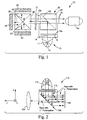
- Fig. 1 illustrates an optical display or imaging system 10 including a light source 12, providing a beam of light 14.
- the light source 12 includes a lamp 11 and a reflector 13. Suitable lamps include Xenon, incandescent, laser, LED, metal halide arc or highpressure mercury light source(s).
- the beam of light 14 passes through illumination optics 15, which may pre-polarize the light, and impinges upon a Cartesian PBS element 50.
- the Cartesian PBS element 50 includes a layer of 3M advanced multi-layer polymeric film (3M advanced film) 52 encased in a glass cube 54, and oriented so as to reflect light incident with y polarization.
- Wire grid polarizers or 3M advanced film polarizers may be used alone (see Figs. 2 and 3) though they also may be used in cube configurations.
- Most 3M advanced film polarizers used in the present embodiment function best between sheets of glass or as a pellicle, i.e. in configurations where-in the angles of transmission through the film are turned toward the film normal by Snell's law as the light enters the material medium.
- Other 3M advanced multi-layer film PBS's have been prepared which function well in glass cubes of arbitrary index, where-in the angles of transmission through the film have not been turned toward the film normal as the light enters the embedding medium from air.
- Films which function well in glass cubes have additional requirements to ensure appropriate values of the anisotropic indexes of refraction for each layer, especially in the direction normal to the surface of the film.
- the indices of refraction in the thickness direction the film, of alternating layers are ideally the same. This is in addition to the indices in the X direction (pass direction) of the polarizer being equal.
- both the X and Z (normal to the film) indices of the alternating layers must be matched. Achieving a match for both the X and Z indices requires a different material set than that used when only the X index is matched.
- Older 3M multi-layer films, such as 3M brand "DBEF" film were made in the past with a match to the X index.
- One method of matching both the X and Z indices of all the layers is to impart a true uniaxial stretch wherein the film is allowed to relax (i.e. shrink) in both the X and Z directions while it is being stretched in the Y direction. In such a manner, the X and Z indices of refraction are the same in a given layer. It then follows that if a second material is chosen which matches the X index of the first material, the Z indices must also match because the second material layers are also subjected to the same stretching conditions.
- the allowed magnitude of the Z index mismatch is always relative to the Y index mismatch because the latter value determines the number of layers required in the polarizer thin film stack.
- the total reflectivity of a thin film stack is controlled equally by the index mismatch ⁇ n and the number of layers in the stack N, i.e., the product ⁇ n ⁇ *N determines the reflectivity of a stack.
- the ratio of ⁇ n Z / ⁇ n Y is the relevant parameter that must be controlled.
- the ratio ⁇ n Z / ⁇ n Y is preferably less than 0.5 and more preferably less than 0.2.
- the ratio ⁇ n Z / ⁇ n Y is preferably less than 0.2, more preferably less than 0.1 and most preferably less than 0.05.
- ⁇ n X must also be very small compared to ⁇ n Y and if ⁇ n Z is very small, the ratio is preferably less than 0.1 for films used in air. For immersed films the ratio is preferably less than 0.1 and most preferably less than 0.01. However, as described in co-assigned U.S. Pat. Appln. No. 08/958,329, relevant portions of which are hereby incorporated by reference, if ⁇ n Z is not zero, then a small mismatch in the X indices can be used to improve the transmission of p-polarized light.
- the Z index mismatch is irrelevant for the transmission of s-polarized light.
- s-polarized light does not sense the Z-index of refraction of a film.
- the reflective properties of birefringent multilayer polarizers at various azimuthal angles are such that a projection system performance is superior when the beam splitter is configured to reflect y polarized (approximately s-polarized) light and transmit x-polarized (approximately p-polarized) light.
- a beam splitter that reflects x-polarized light and transmits y-polarized light would work well along the major optic axes, but for a light ray having a finite cone angle, the contrast degrades quickly as the cone angle increases. For film immersed in a cube, the problem is even more severe.
- the preferred PBS configuration reflects y-pol and transmits x-pol.
- the cube configuration is especially advantageous in cases where sensitivity to astigmatism, such as that created by light passing through a tilted glass slab, is high, or where a reduced optical path length is important.
- the cube configuration has the disadvantages, shared by MacNeille polarizers, of suffering from thermally-induced stress-optical effects and increased weight.
- a polarized beam 18 comprising the y-components of the beam 14 is directed towards a color splitter/combiner prism 36, that splits the y-polarized beam 18 into three sub-beams 20, 22, and 24.
- the polarized sub-beams 20, 22, and 24 are reflected and modulated respectively off red, green and blue reflective imagers 26, 28, and 30.
- current reflective LCD light valves have ordinary and extraordinary axes for their dark and light states which are best described in fixed Cartesian coordinates and the fixed polarization axes of Cartesian PBS are better suited to match the Cartesian construction of the imagers.
- the reflected and modulated sub-beams are recombined by the combiner 36 into a combined beam 32 having x-polarization.
- the modulated components of the combined beam 32 pass through the PBS element 50 and are projected as an image by projection lenses 34.
- the exemplary illumination optics 15 in the present embodiment may include a pre-polarizer or polarization converter 15a before the PBS cube 50, and a cleanup polarizer 15b after the PBS cube 50.
- the illumination optics 15 illuminates the imagers 26, 28, and 30 with light having an f /# equal to or lower than 2.5.
- the imagers 26, 28 and 30 may be smectic, nematic, or other suitable reflective imagers. If smectic, the imagers 26, 28, and 30 of the optical imaging system 10 of Figs. 1 and 2 may be ferroelectric liquid crystal display (FLCD) imagers.
- FLCD ferroelectric liquid crystal display
- the combination of a Cartesian PBS and smectic LCD imagers allow optical systems having a very low f /#.
- Smectic LCD's such as FLCD's, typically have particularly wide acceptance cones, and therefore better take advantage of the low f /# capabilities of the systems in accordance with the present invention.
- a multi-layer polymeric PBS with FLCD reflective imager device takes advantage of the low f /# capabilities and fast optical beams that may be used with the present invention.
- Exemplary smectic light valves include ferroelectric liquid crystal display (FLCD), anti-FLCD (AFLCD), analog FLCD, and electroclinic LCD mode light valves.
- Exemplary nematic liquid crystal light valves include twisted, vertically aligned, hybrid aligned, and Pi-cell.
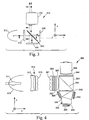
- Fig. 2 illustrates a second embodiment of a projection system 110, including a light source 112, such as, for example, an arc lamp with a reflector.
- the light source could also be a solid state light source, such as light emitting diodes or a laser light source.
- the system 110 further includes a Cartesian PBS 150, an imager 126, illumination optics 115, and a focusing lens 134.
- the PBS 150 is a freestanding Cartesian PBS, such as a wire grid polarizer or a 3M advanced multi-layer film laminated between glass panes.
- Figure 2 illustrates the beam path and ray polarization.
- Light with y-polarization (approximate s-polarization) is indicated by the circled x, showing that the polarization is into the page.
- Light with x-polarization (approximate p-polarization) is indicated by the solid arrow depicting the polarization vector.
- Solid lines indicate incident light, while dashed lines show light that has been returned from the imagers with a changed polarization state.
- Light, provided by the source is conditioned by the illumination optics 115.
- the y components of the light are reflected by the Cartesian PBS 150 and impinge on reflective imager 126.
- the reflective imager reflects and modulates an image beam having x-polarization.
- the reflected x-polarized beam is transmitted by the PBS 150 and is focussed by the focussing lens 134.
- Many design specific components of a projection system such as filters for the light, beam homogenizers, polarization converters, relay or field lenses and the like, are omitted from the figures as unnecessary to this discussion, but may be placed by those skilled in the art.
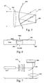
- Fig. 3 illustrates a third embodiment of a projection system 210 in accordance with the present invention that also uses the transmitted x-polarized components of the original beam.
- the system 210 includes a light source 212, a Cartesian PBS 250, a first imager 226, a second imager 228, illumination optics 215, and a projection lens 234.
- the imagers 226 and 228 are sequential color or monochrome.
- Light from the light source 212 passes through the illumination optics 215 and is incident on the PBS 250.
- the PBS transmits the x-polarization component of the light and reflects the y-polarization component.
- the x-polarization component is reflected and modulated by the first imager 226 into a y-polarized beam that is reflected by the PBS 150 into the projection lens 234.
- the y-polarization components are reflected and modulated by the second imager 228 into an x-polarized beam that is transmitted by the PBS 250 into the projection lens 234.
- Light returned from the projector in its original polarization state is not depicted on the figure. This light will return from the imager and the PBS will direct the light back toward the lamp.
- Fig. 4 illustrates a fourth exemplary embodiment of a projection system 310 in accordance with the present invention having a light source 312.
- Light is generated by an arc lamp 311 and collected by an elliptical reflector 313, which sends the light toward illumination optics 315.
- the illumination optics 315 include a collimating lens 317, a first lenslet array 319, a second lenslet array 321, and a condensing lens 327. Between the second lenslet array 321 and the condensing lens 327, an optional polarization converter 323, such as those of a Geffcken-type design, may follow. Depending on the conversion efficiency of the polarization converter 323, it may be advantageous to include an optional pre-polarizer 325, immediately following the polarization converter.
- the pair of lenslet arrays 319 and 321 receives nominally collimated light from the collimating lens 317.
- the polarization converter 323 and the prepolarizer 325 polarize the light in the desired direction.
- the lenslet arrays 319 and 321 and the condensing lens 327 serve to shape and homogenize the light in order to illuminate evenly the reflective imagers 326, 328 and 330.
- a Cartesian PBS 350 will then redirect the y-polarized light towards three reflective imagers 326, 328 and 330.
- the PBS surface 352 may be free standing, between glass plates, or encased in a glass prism 354 as shown in Fig. 4.
- a color-separating prism 336 separates the light into its primary colors: red, green, and blue.
- Intervening lenses such as field lenses 338, 340 and 342, may be inserted between each imager and the color-separating prism 336 to further optimize the optical response of the entire system.
- the imagers 326, 328, and 330 will modulate the polarization state of the light upon reflection to varying degrees depending on particular image information.
- the color-separating prism 336 recombines the red, green, and blue images and passes the light to the Cartesian PBS 350, which analyzes the polarization state of the image by passing substantially only the x-polarized light.
- the y-polarized light is redirected back towards the light source 312.
- the light that passes the Cartesian PBS 350 is collected by the projection lens 334 and focussed onto a front or rear projection screen (not shown) for viewing.
- An optional post-polarizer 344 may be inserted between the PBS 350 and the projection lens 334.
- Cartesian polarizers even may be curved along one or two axes. MacNeille PBS systems or Frustrated Total Internal Reflection PBS systems do not offer such flexibility.
- FIG. 5 illustrates an optical imaging system 410 including a curved Cartesian PBS 450, a light source 412, a reflective LCD imager 426 and an eyepiece lens 434.
- the light source 412 may contain reflective and refractive beam shaping and conditioning elements.
- the curved PBS 450 may be curved along one or two orthogonal in-plane axes, i.e., it may possess either a simple or compound curvature.
- Systems utilizing a PBS that has a curvature along one axis may require cylindrical lenses to shape the beam along the orthogonal axis.
- Curved polarizers may be useful in both front and rear projection systems, as well the so called micro displays which project directly into the viewer's eye, or systems which form a virtual image by reflection from a semitransparent surface as in the "heads up" display.
- a 2D curved PBS has been reduced to practice using the technique diagrammed in Fig. 6.
- a 3M multi layer reflective polarizer optical film (“MOF") 550 was stretched over a hole 560 in a plate 562 and a vacuum was applied to pull the film 550 through the hole 560. Heat was applied with a heat gun to soften the film 550 and deepen the sag. When cooled, the film retained its concave shape.
- the curved MOF acted as a curved Cartesian PBS, focusing the reflected light of one polarization and transmitting the orthogonal polarization. Multiple diameters and heating times were tried. In all cases, the polarization extinction was maintained out to the very edge of the concave shape.
- a curved PBS with an elliptical edge could also be made by vacu-forming through an elliptical hole.
- the axis of polarization of the curved PBS could be controlled, depending on the alignment of the optical axes of the MOF to the major axis of the hole.
- the optical train of a micro-display using a curved PBS was demonstrated, as illustrated in Fig. 7.
- Light from a diffuse source 512 was passed through illumination optics 515, pre-polarized, reflected off of the curved PBS 550 and reflected off of a quarter-wave mirror (QWM) 558.
- the resulting polarization rotation allowed the light to then pass through the PBS 550 to an eyepiece 534.
- the curvature served to concentrate the illumination light onto the QWM 558 that resulted in a brighter image than that from a planar PBS.
- Rotating the QWM 558 45° about the normal axis presented a dark state to the eyepiece 534 that included a dark central band characteristic of thin film polarizers. It was observed that the image of the QWM 558 in the bright state angular range was compressed in horizontal plane.
- the source (a diffuse small backlight) 412 and imager 426 co-planar, and along the same axis as the eyepiece 434, good illumination was obtained off the imager 426 with no apparent image distortion. It was also found that the distance between the source/imager plane and the curved PBS 450 was not particularly critical. The most compact design has the center of the curved PBS 450 aligned with the common edge of the imager 426 and the adjacent source 412. Tilting the source 412 improved illumination somewhat. The output of the source was polarized by a dichroic polarizer.
- Figure 8 illustrates another embodiment, optical imaging system 610, where the source 612 is above the imager 626.
- a curved QWM 658 is used to rotate the polarization of the incident light initially transmitted through the curved Cartesian PBS 650.
- the additional beam shaping from the curvature of the QWM 658 may be used to optimize the illumination of the imager 426.
- a MOF polarizer can be shaped into a multiplicity of curved surfaces to create a means to image an inhomogeneous source onto a plane or other desired loci to improve homogeneity. This could be used to replace or augment a lenslet array commonly employed in projection systems to provide uniform illumination.
- Fig. 9 illustrates an optical imaging system 710 including a lenslet-shaped Cartesian PBS 750. Experimentation has shown that the source area 712 was optimally trapezoidal in shape to obtain uniform illumination onto the imager 726.
- Fig. 10 illustrates an optical imaging system 810 including a double-curve Cartesian PBS 850 and a dual light source planes 812.
- a single lamp 811, illumination/conditioning optics 815 and a lenslet array 817 may be used to provide the dual light source planes 812.
- the dual source beams are reflected off the curved Cartesian PBS 850 and then off the imager 826.
- a projection lens or eyepiece 834 prepares the transmitted beams for projection or viewing.
- Use of two sources (or two source planes) is possible if two curved PBS's are used, joined at one edge (could be one molded piece).
- the union line 853 would ideally be above the center line of the imager.
- the same concept could be used in projection systems where the "source planes" represent planes of homogeneous illumination.
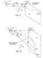
- Figs. 11-18 illustrate the compound angle depolarization effects or depolarization cascade problem.
- MacNeille PBS systems based on Brewster angle reflection are more adequately described in cylindrical coordinates around the normal axis of the PBS coating, as the function of the MacNeille PBS depends on the angle of incidence of the incident light.
- imaging systems include imagers that function with respect to fixed orthogonal axes. The ramifications of this qualitative difference can be discerned by considering the prepolarized light rays, Rays 1-4, depicted in Figs. 11 and 12.
- the x, y, and z axes are referenced with respect to the principal ray, with the z axis parallel to the propagation vector of the principal ray and the y axis aligned with the pre-polarizer transmission axis.
- the x, y, and z axes are shown for the light passing between a pre-polarizer and a PBS.
- the y-axis is referenced in the present example as the vertical direction.
- the principal ray is normal to the surface of the reflective imager.
- the axes of the rays after reflection from the PBS are identified by x', y', and z'. Note that the directions y and y' are parallel.
- Real light sources project light beams in the shape of a cone, where all the light rays are not perfectly collimated.
- Real projection systems therefore, generally use cones of light. These cones are defined by a cone angle.
- the cone angle is the smallest angle that includes all of the rays from that beam of light that may be used by the projection system.
- Rays 1, 2, 3 and 4 in Figs. 11 and 12 illustrate four different types of light rays found in such a cone of light.
- a light source 70 produces a light cone that is first conditioned by a pre-polarizer 72.
- the rays are shown with large values of deflection. It should be understood that all rays would be incident upon a PBS 74.
- Ray 1 is a principal ray parallel to a z-axis.
- Rays 2-4 are skew rays, that is, rays that are not parallel to the principal axis (z).
- the propagation vector, k 2 , of Ray 2 has an x component and is horizontally angled, that is, the end of the k 2 vector is horizontally displaced in the horizontal x-z plane from that of a principal ray originating from the same location on the pre-polarizer as Ray 2.
- the propagation vector of Ray 3, k 3 has a vertical component and is vertically angled (the end of the k 3 vector is vertically displaced in the vertical y-z plane from that of a principal ray originating from the same location on the pre-polarizer as Ray 3).
- Ray 4 is both vertically and horizontally angled.
- the relative amounts of each of these four types of rays in the cone of light of a projection system will depend on the details of the illumination system.
- a common metal halide or Xenon lamp source in a typical illumination system will, from simple phase space considerations, provide very few type 1 rays, as many type 2 as type 3 rays, and more type 4 rays than of any other type.
- Ray 1 of Figure 11 is a principal ray of the projection system and is pre-polarized in the y direction by the pre-polarizer 72. Ray 1 will be 100% reflected by a perfect reflective polarizer oriented to reflect either y or s-polarization, be it a Cartesian polarizer or a MacNeille polarizer. The pure y-polarization of this ray is also pure s-polarization for the MacNeille PBS, that is, the polarization vector is perpendicular to the reflection plane for the ray as it is reflected by the PBS (the x-z plane of Figure 11).
- Ray 1 If subsequently reflected from a mirror or mirror-like imager placed along and perpendicular to the z' axis, Ray 1 will remain both purely y and purely s polarized after reflection, and be reflected back into the light source with high efficiency. Thus rays of light similar to Ray 1 will provide a very good, low leakage dark state, and a very high contrast ratio when used with either a Cartesian or a MacNeille PBS. Unfortunately, most light sources cannot provide perfectly collimated light.
- Ray 2 has been horizontally deflected from Ray 1, so that Ray 2 has a propagation direction (k 2 vector) having an x component.
- Ray 2 is contained in the x-z plane, that is, Ray 2 has an angular displacement within the horizontal plane. Because the x-z plane is still the reflection plane, Ray 2 is still purely y polarized both before and after reflection from the PBS, and after reflection from a mirror-like imager placed along and perpendicular to the z' axis.
- Ray 2 also has the property that y-polarization is identical to s-polarization, so once again both ideal MacNeille and ideal Cartesian polarizers should provide equivalent, high contrast for Ray 2-type rays, so long as the deflection does not cause the ray to deviate too much from the Brewster's angle. If this happens, the MacNeille polarizer will reflect both s and p-polarized light, causing the ray returning from the imager to be reflected back to the lamp.
- Ray 3 in Fig. 12 has been deflected from Ray 1 such that Ray 3 is contained in the y-z plane.
- Ray 3 is vertically skewed with respect to Ray 1 and is angularly displaced along the vertical plane.
- Ray 3 also includes a component of polarization along the z direction.
- the reflection plane for resulting Ray 3" is no longer the same as it was for Ray 3'. Because the polarization vector of Ray 3" has not been affected by reflection, this rotation of the reflection plane means that the Ray 3" is no longer purely s-polarized, but is now partially p-polarized.
- Figs. 13-20 better illustrate the reflection of a Ray 1, the principal ray, and of the vertically skewed Ray 3 off a PBS.
- the x and z axes rotate about the y axis to keep the z axis aligned with the propagation direction of the principal ray.
- the rotated axes are labeled x', y' and z' and the reflected rays are labeled Ray 1' and Ray 3' respectively.
- Figs. 13-16 illustrate the paths of Rays 1 and 3 when reflected off a PBS 74.
- the PBS 74 comprises a cube 76, shown in dashed lines, having a PBS surface 78 located along an internal diagonal plane of the cube.
- the cube has an incident face 80 that receives the incident light rays and an exit face 458 through which the rays, which are reflected off the PBS surface exit the cube.
- Fig. 13 is an incident side perspective view and Fig. 14 is an exit-side perspective view.
- Fig. 15 is a plan top view of a top face 84 and Fig. 16 is an incident-side elevation view of the PBS 74.
- Ray 3 shown by the dash-dot vector, propagates at a 30° angle with respect to Ray 1 along the y-z plane.
- Ray 1 also is contained in the same y-z vertical plane.
- both rays have been illustrated as having the same point of contact P on the surface of the PBS 74, marked by the intersection of perpendicular dot-dash axes.
- the Ray 1' Upon reflection from the PBS 74, the Ray 1' propagates in the negative x (z') direction, while Ray 3' deviates 30° in the x-y (_y,z') plane.
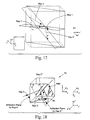
- Fig. 17 is the equivalent of Fig. 14 in which the PBS surface is the traditional MacNeille type, and indicates the effects of reflection on the polarization state of initially unpolarized rays of light, 1 and 3.
- the polarization states of the reflected components of Rays 1' and 3' are illustrated by small direction arrows.
- the reflective surface normal is shown as â. It may be appreciated that the s-polarization states of both Ray 1 and Ray 3 are reflected.
- traditional reflective polarizers operate based on the plane of incidence of the incoming rays, the reflected polarization states for Ray 1' and Ray 3' each are perpendicular to the plane of incidence for each respective ray.
- the polarization state of the Ray 3' is rotated away from the y, z' plane, as illustrated in Fig. 17. That is, in a system including a traditional MacNeille polarizer, the reflection of a vertically skewed ray is depolarized with respect to the reflection of the principal ray. The larger the skew angle, the larger will be the depolarization effect. For a skew angle of 30°, the depolarization effect is a 39.2° rotation of the reflection plane, and consequently of the polarization state of s polarized light from the desired y, z' plane..
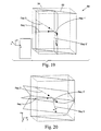
- Fig. 19 illustrates the reflection (Rays 1' and 3') of both unpolarized Ray 1 and Ray 3 off the Cartesian PBS 50 of display system 10.
- the Cartesian PBS 50 has a fixed vertical reflection axis.
- the Cartesian PBS 50 includes a 3M advanced multi-layer birefringent film, or other suitable Cartesian PBS, such as a wire grid polarizer, or any other Cartesian polarizer PBS.
- Fig. 18 illustrates in simplified detail the reflection of Ray 3' off the PBS 74 and the subsequent reflection, Ray 3", off a reflective imager 86.
- a mirror is used as an ideal imager to avoid the contrast degradation associated with imager performance factors, such as diffraction and scattering due to pixelation or stray retardation in the imager dark state.
- a mirror does not rotate the polarization state of the light and represents the function of an ideal reflective LCD imager for most nematic modes in the dark state.
- the depolarization effect illustrated in Fig. 12 is amplified when the Ray 3" is reflected off the imager 86.
- the polarization vector of the Ray 3" returning from the mirror-like imager will be at an angle 2 ⁇ from the s polarization condition, thus suffering from a depolarization cascade.
- This purely geometrical effect arising from the rotation of the reflection plane results in the mirrored Ray 3" possessing a p component which will leak through the MacNeille PBS, degrading contrast in the dark state for the system.
- Rosenbluth Contrast Properties mentions a method to compensate the depolarization by placing an additional component, a 1/4 wave retarder plate, parallel or perpendicular to the polarization direction of the principal ray.
- Rosenbluth discourages the use of reflective interference coatings by indicating that "Beam-dividing interference coatings give rise to polarization crosstalk via compound-angle depolarization, as illustrated...for a PBS coating....
- the Cartesian polarizer 50 reflects light that is y-polarized and transmits light that is x-polarized. As seen in Fig. 19, this is true even for unpolarized light. Since the Cartesian PBS 50 has a fixed reflection axis that is intrinsic to the material of the PBS and not dependent on the angle of incidence of the light rays, the polarization of an initially y-polarized Ray 3 when reflected as skew Ray 3' is not significantly rotated with respect to that of the reflected principal Ray 1'. The polarization state of the reflected Ray 3' is restricted to lie in the y-z' plane containing the reflected ray and the vertical axis of the PBS 50. The reflected Ray 3' has no substantial x' component.
- y-polarized light is presented to subsequent inclined reflecting surfaces regardless of the incident angle of the skew rays. While the reflecting surfaces may introduce some depolarization of their own, the reflecting surfaces will not amplify the pre-existing depolarization of the ray, since that depolarization will not exist or be minimal. This effect both ensures that the LCD imager is presented with a ray that is nearly purely y-polarized, and will minimize the degree of rotation introduced prior to reaching the imager.
- the present invention enables optical imaging system embodiments that may utilize light rays having a very wide range of angles of incidence.
- Optical systems in accordance with the present invention have illumination optics having f /#s lower than 2.5, with acceptable system contrast. Acceptable contrast is defined as at least 100:1 over all color bands of interest in projection systems using a reflective mirror as an ideal imager.
- the system 10 of the present invention including the Cartesian polarizer 50 has been experimentally tested with illumination optics having a lens speed of f /1.8, while providing a contrast ratio of over 200:1.
- optical systems according to the present invention minimize depolarization by the use of the Cartesian, as opposed to MacNeille PBS.
- the present invention allows the use of optics having extremely low f /#'s.
- the system of the present invention provides further benefits for skew rays that are both vertically and horizontally angled with respect to the principal ray.
- Ray 4 is both vertically and horizontally angularly displaced.
- the polarization vector for Ray 4 contains components in the x direction as well as in y and z. All of the depolarization effects described for a reflected Ray 3' will occur upon a reflected Ray 4' in a system including a traditional "plane-of-incidence" dependent polarizer.
- an LCD imager will be presented with an additional component of x' polarized light along with the dominant y-polarization.
- the depolarized component will be amplified upon reflection from subsequent inclined reflecting surfaces, such as a MacNeille PBS or color-separating surface.
- the amplified depolarization component will cause the same degradation in the dark state as for rays of type 3.
- the optical imaging system of the present invention using Cartesian PBS's generally will minimize the reflected the x component of polarization and will therefore provide superior performance.
- the present invention further discloses additional advantages to the use of reflective Cartesian polarizers in a projection system.
- the Cartesian polarizers may be oriented at arbitrary angles of incidence or be shaped to minimize volume, achieve keystone correction, or otherwise optimize the performance of the projection system.
- the Cartesian PBS is oriented at an angle between 40° and 50° with respect to the principal ray.
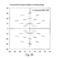
- Fig. 20 shows the polarization direction of Rays 1' and 3' if the PBS 50 is rotated 90° about the surface normal.
- the PBS reflection Material Axis is now horizontal instead of vertical.
- the polarization state suffers a similar but opposite rotation as that for the MacNeille PBS of Fig. 17.
- it is preferable that the polarization direction be perpendicular to the propagation direction of Ray 3', k 3 , and contained in the plane defined by the reflection Material Axis and k 3 .
- the rotation of the polarization state of Ray 3' with respect to Ray 1' is shown in Fig. 20.
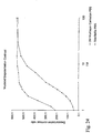
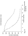
- Figs 24 and 25 illustrate the results of a computer modeling of depolarization contrast ratio vs f /# and acceptance angle for traditional PBS systems and the exemplary 3M Film Cartesian PBS 50. It may be noted that the Cartesian PBS Systems in accordance with the present invention provide far better contrast ratio at lower f /#'s and wider acceptance angles.
- FIG. 2 A compact and cost-effective LCD projector configuration using reflective LC microdisplays for which the PBS serves as both polarizer and analyzer, is depicted in Figure 2.
- a projection display test bed implementation of Figure 2 was built and used to compare the performance of a system in accordance with the present invention.
- a first system was tested including a wide-angle Cartesian PBS, while a second system was tested employing a high-performance Brewster's angle PBS.
- a 3M multi-layer polymeric PBS film laminated between two 0.3 mm or two 0.7 mm glass sheets was used as a representative wide angle Cartesian PBS.
- PBS components were tested in an optical imaging system having illumination optics between f /1.8 and f /8.0, first with fiber light illumination.
- the illumination profile of fiber light illumination varies smoothly, was nearly Lambertian and did not uniformly illuminate the imager.
- the effects of the reflective imager were modeled by replacing the imager with a 1/4 wave film, such as quarter-wave film from Edmund Scientific from Barrington, NJ, laminated to a front surface mirror.
- a 1/4 wave film such as quarter-wave film from Edmund Scientific from Barrington, NJ
- the arrangement modeled LC modes that vertically turn the LC to the optic axis, such as TN or VAN (vertically aligned nematic) modes.
- contrast measurements are made by measuring light throughput at nine locations on the projection screen for both the dark and light states, then calculating the ratio of these measurements.
- the ratio is referred to as the contrast dynamic range.
- the contrast dynamic range is one measurement of the contrast ratio.
- the contrast dynamic range ratio is defined as the projected light throughput in the brightest state divided by the light throughput in the darkest state. Because, as indicated above, the fiber light does not uniformly illuminate the imager, a single-point measurement at the center of the screen, where the light is brightest, was used for the fiber illumination case. Contrast dynamic range results should therefore be understood to be either single point values at the center of the screen for fiber illumination, or nine point averages in all other cases.
- color bands refers to wavelength bands into which white light is separated for independent modulation, prior to being recombined into a colored image. These bands are typically less than 1 00nm wide, for example 50-70 nm, and are often selected so as not to include light that is detrimental to color gamut, such as yellow and cyan light in a three-band, red/green/blue image forming system. While the exemplary data in Table 2 does not explicitly demonstrate separate red, green, and blue contrast levels exceeding 100:1 for the system of the present invention, the Tables below illustrates contrast levels exceeding 100:1 for other illumination sources. It is clear though, that for quasi-lambertian white light contrast the Cartesian PBS is markedly superior to the MacNeille PBS.
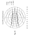
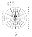
- Figs. 21-23 depict the dark state light present at the pupil of the f /2 projection lens after passing through the projector test bed of Fig. 2, including pre- and post-polarizers. At the pupil of the projection lens light is spatially sorted by angle. Therefore, these images are depictions of conoscopic plots of the dark state light transmission vs. angle of incidence. These images may be compared to Figures 32-34, which are calculated contrast results. For these results, which will be described more fully below, a quarter wave film was used to provide a bright state for calculating contrast ratios, and a mirror was used to represent the dark state depicted in the figures.
- the images of Figs. 21-23 were taken with a digital camera that adjusted its gain automatically to provide good image quality; otherwise all images were taken under identical conditions. Because the camera adjusts gain, these images can only be used qualitatively. Full screen contrast values associated with each image will be provided below for comparison.
- Fig. 22 depicts the dark state performance of a MacNeille polarizer.
- a color depiction is it notably red along the left hand side, corresponding to light incident on the PBS coating at angles closer to normal than 45°.
- It has a quite deep Maltese band of good contrast, but the band is also quite narrow and the type 3 and 4 skew rays, present at the top and bottom of the image, cause a notable increase in bright-ness.
- the white contrast on screen associated with this pupil image is 53:1, however the contrast over a particular color band may be lower than this due to the observed red leak.
- Fig. 21 shows the pupil image for a dark state of the exemplary system using 3M DBEF.
- This image has a much less dark, but broader, Maltese band.
- As projected on the screen there was a slight red coloration in vertical bands across the image, as well as a pronounced blue/green coloration to the Maltese band, especially on the left hand side of the band. This redness is less pronounced than for the MacNeille PBS.
- the broader Maltese band and the reduced skew ray leakage that can be seen for this polarizer are expected, since it is a Cartesian polarizer. The reason the performance is inadequate is that the polarizer has not been designed for high extinction.
- Fig. 23 shows the dark state performance of the 3M Multilayer polymeric PBS. The overall darkness of the image is striking, despite the automatic gain adjustment of the camera.
- the width of the Maltese band is much broader than for either the MacNeille PBS or the DBEF PBS, and the leakage of type 3 and 4 rays is much less severe than in either of the other cases.
- the white light contrast measured with this PBS was 222:1. Color band contrast for this PBS will be described more fully in Example 2.
- Figs. 31-35 present results that further and more quantitatively illustrate how a Cartesian polarizer optical imaging system improves performance of the illumination leg of a projection system.
- a computer code was used to model the transmission or reflection of a Stokes vector from surfaces or multilayer stacks.
- Luminous intensities for the various polarization states were obtained by weighting the result at each wavelength with the value of the CIE 1931 photopic response function and the radiance of an equal-energy Lambertian illuminant and integrating over all wavelengths from 400 to 700 nm. In this manner results such as polarization state and contrast ratio were obtained for each ray in a conical bundle.
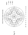
- Figs. 31-35 depict conoscopic plots.
- a conoscopic plot presents data that vary with the polar coordinate angles, ⁇ and ⁇ by using a two-dimensional polar coordinate system with ⁇ as the radial coordinate. This maps the upper hemisphere onto a disc and plots data along rings of constant ⁇ and rays of constant ⁇ .
- Conoscopic plots are commonly used to depict the angular performance of devices such as liquid crystal displays through a plot of angular contrast ratio, i.e., contrast ratio (CR) versus viewing angle.
- CR contrast ratio
- a technique to plot sets of polarization data conoscopically also was developed.
- Fig. 31 shows a conoscopic CR contour plot computed for a vertical or Y-oriented linear polarizer lying in the X-Y plane and analyzed with a second, identical polarizer lying in a plane parallel to the first.
- Polarizer orientation is used to refer to the orientation of its transmission axis.
- the light state occurred when the analyzer was oriented parallel to the Y-axis and the dark state when the analyzer was perpendicular to it.
- a common way to describe the polarization state of a light ray is with its polarization ellipse, i.e. the curve swept out by the end point of the electric field vector over a period of oscillation.
- the ellipse graphically displays the magnitude and orientation of the polarization state of the light ray with respect to a pair of orthogonal reference axes lying in a plane perpendicular to the ray direction.
- Important special cases include circular polarization (where the ellipse becomes a circle) and linear polarization (where the ellipse degenerates into a straight line).
- a polarization ellipse in the local s-p coordinate system defined by ⁇ and ⁇ can be rotated (by - ⁇ ) and plotted in a global X-Y coordinate system.
- This transformation allows one to present several angle-dependent polarization data sets with a single common reference. For example, plotted this way a narrow vertical ellipse would indicate a nearly linear polarization in the Y-Z plane.
- Fig. 34 shows a conoscopic CR contour plot for a y-oriented linear polarizer lying in the x-y plane, followed by a biaxial multilayer polymeric reflecting polarizer with a reflection axis parallel to the y-axis and a surface normal oriented at 45° to the x-y plane.
- This particular reflecting polarizer was designed specifically for use as a Cartesian-type polarizing beam splitter.
- An analyzing polarizer (identical to the first linear polarizer) was placed in the y-z. The light state occurred when the analyzer was oriented to pass light polarized parallel to the y-axis and the dark state when the analyzer oriented to block light polarized parallel to the y-axis.
- the highest angular CR computed for the combined polarizer plus beam splitter was much larger than for the polarizer alone, while the lowest computed CR was much smaller.
- the reflecting polarizer acts on light from the first polarizer. The first is by a reduction in the amount of unpolarized light. A reduction in unpolarized light is a reduction in the amount of unwanted polarization.
- the reflecting polarizer actually increases the degree of polarization (DP) of the light over a limited range of angles. Light emerges from the first polarizer with high DP, in this case about 99.80% to 99.90%, but by cascading with the beam splitter the DP is increased to as much as 99.98%.
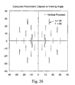
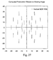
- Fig. 27 shows the computed polarization ellipses for the vertical polarized light after reflection by the PBS.
- a comparison with Fig. 26 reveals that while the reflecting polarizer has not added ellipticity, it has rotated the polarization. Regions with ellipses significantly rotated from vertical are seen to be the same regions with low angular CR in Fig. 34.
- depolarization contrast ratio (DCR) vs. f /# of optical imaging systems including a traditional PBS and systems including a Cartesian PBS.
- Figures 24 and 25 are plots of these results.
- the depolarization contrast ratio is defined as the ratio of the transmittance of the reflected light exiting a pre-polarizer/PBS through a vertical (y) analyzer vs. a horizontal (x') analyzer.
- y vertical
- x' horizontal
- the wide-angle Cartesian PBS has an exceptional DCR at low f /#s as compared to the MacNeille PBS.
- Angular CR is very similar to the DCR. It is a measure of the beam splitter's ability to maintain the polarization of light it reflects. DCR versus angle, however, is computed by integrating light and dark state luminosity over all ⁇ out to some value of ⁇ and taking their ratio and not by integrating the angular CR.
- the DCRs computed for the polarizer plus beam splitter in Fig. 34 are shown in Figs. 24 and 25. As might be expected, the combined polarizer plus beam splitter has a larger DCR for large f -numbers (small angles).
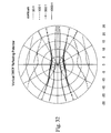
- Fig. 32 also shows the computed angular CR for a y-oriented linear polarizer lying in the x-y plane, followed by a reflecting polarizer with a reflection axis parallel to the y-axis and surface normal oriented at 45° to the x-y plane.
- the 3M advanced film biaxial multilayer polymeric reflecting polarizer in this example was originally designed to enhance the brightness of LCDs over a wide range of angles, similar to 3M's Dual Brightness Enhancement Film (DBEF).
- DBEF Dual Brightness Enhancement Film
- the angular CR pattern shown in Fig. 32 has a narrower band of very high contrast compared to Fig. 34.
- Figs. 32 and 34 The superiority of the optical imaging system designed to include the 3M advanced film for f -numbers less than about f /14 ( ⁇ ⁇ 2°) is clearly shown in Figs. 32 and 34. While it is not obvious by comparing the DBEF polarization ellipse plot (Fig. 28) with the beam splitter plot (Fig. 27), the beam splitter does in fact provide a more nearly vertical polarization over a larger range of angles. It also produces light with a larger DP.
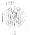
- Fig. 33 shows the computed angular CR for a y-oriented linear polarizer lying in the x-y plane, followed by a 45° MacNeille cube-type reflecting polarizer with its tilt axis parallel to the y-axis.
- the CR was computed by placing an analyzing polarizer (identical to the first linear polarizer) in the y-z plane parallel to the cube output face.
- the angular CR pattern is different from those of the two Cartesian polarizers in having a reduced region of large CR that gets slightly larger along the positive x-axis.
- Figs. 24 and 25 reveals this particular MacNeille polarizer to be significantly worse than either of the Cartesian polarizers at f /2 and to provide useful contrast over a much smaller range of cone angles.
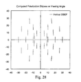
- Fig. 29 a conoscopic plot of the polarization ellipses for the MacNeille polarizer illuminated with initially unpolarized light, also displays a very different behavior from the Cartesian polarizers.
- increasing the angle of incidence rotates the reflection plane of rays striking the 45° coating.
- the coating reflects S-polarization
- the polarization of the reflected ray must rotate as well.
- Fig. 35 reveals that the beam splitter film oriented to reflect horizontally polarized light does a poor job of maintaining the polarization despite its being a good Cartesian polarizer when oriented to reflect vertically polarized light.
- the transmission axis of the first polarizer and the reflection axis of the second were parallel and the reflection was mostly of s-polarized light.
- the transmission axis of the first polarizer and the reflection axis of the second polarizer are merely coplanar and the reflection is predominantly of p-polarized light.
- this Cartesian polarizer to reflect polarized light without rotation requires a preferred orientation of its reflection axis to minimize the variations in reflection with incidence angle.
- Example 2 the systems were tested under the same parameters as in Example 1 with paired lenslet array (Rantsch) illumination, as illustrated in Fig. 4.
- Räntsch illumination the illumination profile was very structured due to the lenslet array integrator and the imager was more uniformly illuminated.
- Räntsch illumination is commonly employed in electronic projectors.
- optical imaging systems were tested using components at f /#'s between 1.8 and 8.0.
- the dynamic range was measured as described above.
- Quarter-wave compensation is accomplished by placing a quarter-wave compensating film (QWF) at 0° to the polarization direction of the light incident on the imagers to supply a dark state.
- QWF quarter-wave compensating film
- the configuration models an FLCD imager.
- the mirror was used alone in the dark state to model a Nematic imager.
- Sufficient illumination was available in the present example to allow the results to be reported by color band.
- Example 2 more closely resembles the arrangement of an actual projection system.
- the contrast performance of the MacNeille cube is much less than that of the wide-angle Cartesian PBS; the difference being much greater than that seen with fiber illumination.
- Reflective nematic LCD based electronic projection system including 3M advanced film Cartesian PBS's were observed to have a number of advantages over systems including MacNeille Polarizer PBS's. These include:
- Cartesian PBS may be applicable to any wide-angle Cartesian PBS.
- Alternative embodiments may include other suitable Cartesian PBS's, such as wire grid polarizers.
- FLCD imagers offer superior contrast relative to TN imagers at very small f /#'s, thereby improving the potential efficiency of light utilization for FLCD relative to TN imagers when used in conjunction with a wide angle PBS.
- the combination of wide-angle Cartesian PBS's and FLCD imagers allows for faster optical beams to be employed in, for example, sequential color systems where the color separating prism does not limit the f /#. In this sort of system, or any other which allows f /#'s below 2 to be used, the contrast advantage of the FLCD with fast optical beams allows a more efficient light throughput.
Claims (22)
- Système optique de formation d'image (10) comprenant :dans lequel la lumière de l'image réfléchie par l'au moins un modulateur de lumière réflecteur est transmise, par l'intermédiaire du séparateur de faisceau de polarisation à grand angle cartésien, dans un second état de polarisation orthogonal par rapport au premier état de polarisation, et a un rapport de contraste d'au moins 100 sur 1 dans chaque bande de couleur projetée de la gamme de lumière visible.au moins un modulateur de lumière réflecteur (26) ;un dispositif optique d'illumination de modulateur de lumière (15) produisant un faisceau lumineux d'illumination frappant l'au moins un modulateur de lumière réflecteur avec un f/# de 2,5 ou moins ; etun séparateur de faisceau de polarisation à grand angle cartésien (50) disposé entre l'au moins un modulateur de lumière réflecteur et le dispositif optique d'illumination de modulateur de lumière, ledit séparateur de faisceau ayant une orientation structurelle définissant des axes fixes de polarisation et séparant la lumière incidente en un premier et un second faisceau sensiblement polarisés ayant des états de polarisation référencés par rapport au système de coordonnées fixes, de telle sorte que le faisceau lumineux soit transmis vers l'au moins un modulateur de lumière réflecteur par l'intermédiaire du séparateur de faisceau de polarisation à grand angle cartésien dans un premier état de polarisation ;
- Système optique de formation d'image selon la revendication 1, dans lequel le système a un angle de cône minimum acceptable d'environ 12 degrés.
- Système optique de formation d'image selon la revendication 1, dans lequel le rapport de contraste dépasse 150 sur 1.
- Système optique de formation d'image selon la revendication 1, le dispositif optique d'illumination du modulateur de lumière ayant un f/# de 2,0 au maximum.
- Système optique de formation d'image selon la revendication 4, dans lequel le rapport de contraste dépasse 150 sur 1.
- Système optique de formation d'image selon la revendication 1, dans lequel le modulateur de lumière est un modulateur de lumière modulant la polarisation.
- Système optique de formation d'image selon la revendication 1, dans lequel le modulateur de lumière réflecteur est un modulateur de lumière à cristaux liquides smectiques.
- Système optique de formation d'image selon la revendication 1, dans lequel le modulateur de lumière réflecteur est un modulateur de lumière à cristaux liquides nématiques.
- Système optique de formation d'image selon la revendication 7, dans lequel le modulateur de lumière réflecteur est un FLCD.
- Système optique de formation d'image selon la revendication 1, comprenant en outre un compensateur en quart d'onde placé optiquement entre le séparateur de faisceau de polarisation cartésien et le modulateur de lumière réflecteur.
- Système optique de formation d'image selon la revendication 1, comprenant en outre un pré-polariseur (15a), dans lequel le pré-polariseur polarise la lumière d'entrée en une lumière pré-polarisée, dans lequel la lumière pré-polarisée comprend la lumière frappant le séparateur de faisceau de polarisation.
- Système optique de formation d'image selon la revendication 1, comprenant en outre un prisme de séparation et de recombinaison de couleurs (36) et une pluralité de modulateurs de lumière réflecteurs, dans lequel le prisme reçoit la lumière polarisée depuis le séparateur de faisceau de polarisation, sépare les couleurs de la lumière polarisée et dirige les faisceaux de couleurs polarisés vers chaque modulateur de lumière.
- Système optique de formation d'image selon la revendication 1, dans lequel le modulateur de lumière réflecteur réfléchit au moins une partie du premier faisceau polarisé vers le séparateur de faisceau de polarisation cartésien.
- Système optique de formation d'image selon la revendication 1, dans lequel le premier faisceau polarisé a un rayon central et le dispositif de formation d'image a une surface réfléchissante définissant un plan de réflexion, dans lequel le rayon central est normal par rapport au plan de réflexion.
- Système optique de formation d'image selon la revendication 1, dans lequel le séparateur de faisceau de polarisation cartésien comprend un film biréfringent multicouche.
- Système optique de formation d'image selon la revendication 1, dans lequel le séparateur de faisceau de polarisation comprend un film multicouche.
- Système optique de formation d'image selon la revendication 1, dans lequel le séparateur de faisceau de polarisation comprend un polariseur à grille de fils.
- Système optique de formation d'image selon la revendication 1, le dispositif optique d'illumination ayant un f/# égal ou inférieur à 1,8.
- Système optique de formation d'image selon la revendication 1, le séparateur de faisceau de polarisation cartésien ayant un axe de rotation et un axe matériel le long duquel la lumière réfléchie est sensiblement polarisée, dans lequel l'axe de rotation est orienté parallèlement à l'axe matériel.
- Système optique de formation d'image selon la revendication 1, dans lequel le séparateur de faisceau de polarisation cartésien est incurvé le long d'au moins un axe.
- Système optique de formation d'image selon la revendication 1, dans lequel on fait tourner le séparateur de faisceau de polarisation par rapport à un rayon central compris entre 40° et 50°.
- Système optique de formation d'image selon la revendication 1 comprenant en outre :a) un prisme de séparation de couleurs (36) aligné optiquement pour recevoir la première composante de polarisation, dans lequel le prisme de séparation de couleurs sépare la première composante de polarisation en faisceaux rouge, vert et bleu ;b) au moins trois modulateurs de lumière réflecteurs (26, 28, 30) alignés optiquement pour recevoir respectivement les faisceaux rouge, vert et bleu ; dans lequel la lumière de l'image réfléchie depuis les au moins trois modulateurs de lumière réflecteurs par l'intermédiaire du séparateur de faisceau de polarisation cartésien a une plage dynamique d'au moins 150 sur 1.
Applications Claiming Priority (3)
| Application Number | Priority Date | Filing Date | Title |
|---|---|---|---|
| US312917 | 1994-09-30 | ||
| US09/312,917 US6486997B1 (en) | 1997-10-28 | 1999-05-17 | Reflective LCD projection system using wide-angle Cartesian polarizing beam splitter |
| PCT/US2000/013525 WO2000070386A1 (fr) | 1999-05-17 | 2000-05-16 | Systeme de projection reflecteur a affichage couleur liquide utilisant un diviseur optique de faisceau de polarisation a grand angle |
Publications (2)
| Publication Number | Publication Date |
|---|---|
| EP1181617A1 EP1181617A1 (fr) | 2002-02-27 |
| EP1181617B1 true EP1181617B1 (fr) | 2003-12-10 |
Family
ID=23213589
Family Applications (1)
| Application Number | Title | Priority Date | Filing Date |
|---|---|---|---|
| EP00936012A Expired - Lifetime EP1181617B1 (fr) | 1999-05-17 | 2000-05-16 | Systeme de projection reflecteur a affichage couleur liquide utilisant un diviseur optique de faisceau de polarisation a grand angle |
Country Status (9)
| Country | Link |
|---|---|
| US (2) | US6486997B1 (fr) |
| EP (1) | EP1181617B1 (fr) |
| JP (1) | JP4638056B2 (fr) |
| KR (1) | KR100702420B1 (fr) |
| CA (1) | CA2387982A1 (fr) |
| DE (1) | DE60007117T2 (fr) |
| MX (1) | MXPA01011639A (fr) |
| TW (1) | TW459146B (fr) |
| WO (1) | WO2000070386A1 (fr) |
Families Citing this family (257)
| Publication number | Priority date | Publication date | Assignee | Title |
|---|---|---|---|---|
| US5882774A (en) * | 1993-12-21 | 1999-03-16 | Minnesota Mining And Manufacturing Company | Optical film |
| US6498683B2 (en) | 1999-11-22 | 2002-12-24 | 3M Innovative Properties Company | Multilayer optical bodies |
| EP0735952B1 (fr) | 1993-12-21 | 2000-03-22 | Minnesota Mining And Manufacturing Company | Film optique multicouche |
| US6486997B1 (en) * | 1997-10-28 | 2002-11-26 | 3M Innovative Properties Company | Reflective LCD projection system using wide-angle Cartesian polarizing beam splitter |
| US7023602B2 (en) | 1999-05-17 | 2006-04-04 | 3M Innovative Properties Company | Reflective LCD projection system using wide-angle Cartesian polarizing beam splitter and color separation and recombination prisms |
| US6587159B1 (en) * | 1998-05-29 | 2003-07-01 | Texas Instruments Incorporated | Projector for digital cinema |
| DE19847161A1 (de) * | 1998-10-14 | 2000-04-20 | Degussa | Mittels Aerosol dotiertes pyrogen hergestelltes Siliciumdioxid |
| JP3609715B2 (ja) * | 2000-11-27 | 2005-01-12 | 三洋電機株式会社 | 色分離合成素子及びそれを用いた液晶プロジェクタ |
| US6597504B2 (en) * | 2000-12-29 | 2003-07-22 | Honeywell International Inc. | Optical devices employing beam folding with polarizing splitters |
| JP2002207120A (ja) * | 2001-01-05 | 2002-07-26 | Nikon Corp | 偏光ビームスプリッタ、投射型表示装置用光学装置、投射型表示装置及び偏光ビームスプリッタの製造方法 |
| JP2003215344A (ja) * | 2001-03-29 | 2003-07-30 | Seiko Epson Corp | 偏光子、およびこの偏光子を用いた光学機器 |
| US6511183B2 (en) * | 2001-06-02 | 2003-01-28 | Koninklijke Philips Electronics N.V. | Digital image projector with oriented fixed-polarization-axis polarizing beamsplitter |
| US6672721B2 (en) * | 2001-06-11 | 2004-01-06 | 3M Innovative Properties Company | Projection system having low astigmatism |
| US6609795B2 (en) * | 2001-06-11 | 2003-08-26 | 3M Innovative Properties Company | Polarizing beam splitter |
| KR20040028778A (ko) | 2001-06-13 | 2004-04-03 | 쓰리엠 이노베이티브 프로퍼티즈 컴파니 | 투사 시스템용 광학 장치 |
| DE60227854D1 (de) | 2001-10-01 | 2008-09-04 | Sony Corp | Polarisationsselektives Prisma für einen Projektor |
| CN1568437A (zh) * | 2001-10-09 | 2005-01-19 | 皇家飞利浦电子股份有限公司 | 光学装置 |
| US6515801B1 (en) | 2001-12-21 | 2003-02-04 | Koninklijke Philips Electronics N.V. | Lateral color compensation for projection displays |
| US6909473B2 (en) | 2002-01-07 | 2005-06-21 | Eastman Kodak Company | Display apparatus and method |
| EP1337117A1 (fr) * | 2002-01-28 | 2003-08-20 | Thomson Licensing S.A. | Système de projection stéréoscopique |
| JP3858723B2 (ja) * | 2002-02-26 | 2006-12-20 | 株式会社日立製作所 | 光学ユニット及びそれを用いた投射型プロジェクタ装置 |
| AU2003213290A1 (en) * | 2002-02-28 | 2003-09-16 | 3M Innovative Properties Company | Compound polarization beam splitters |
| CN2563599Y (zh) * | 2002-05-14 | 2003-07-30 | 邵剑心 | 一种新型硅基液晶彩色微显示器件 |
| US6805445B2 (en) * | 2002-06-05 | 2004-10-19 | Eastman Kodak Company | Projection display using a wire grid polarization beamsplitter with compensator |
| US6634756B1 (en) * | 2002-06-27 | 2003-10-21 | Koninklijke Philips Electronics N.V. | Beam-splitter folded path for rear projection displays |
| DE10255603A1 (de) * | 2002-11-28 | 2004-06-17 | Carl Zeiss Jena Gmbh | Projektionsvorrichtung |
| US7157839B2 (en) * | 2003-01-27 | 2007-01-02 | 3M Innovative Properties Company | Phosphor based light sources utilizing total internal reflection |
| US7118438B2 (en) * | 2003-01-27 | 2006-10-10 | 3M Innovative Properties Company | Methods of making phosphor based light sources having an interference reflector |
| US7091653B2 (en) | 2003-01-27 | 2006-08-15 | 3M Innovative Properties Company | Phosphor based light sources having a non-planar long pass reflector |
| US20040145312A1 (en) * | 2003-01-27 | 2004-07-29 | 3M Innovative Properties Company | Phosphor based light source having a flexible short pass reflector |
| US7245072B2 (en) * | 2003-01-27 | 2007-07-17 | 3M Innovative Properties Company | Phosphor based light sources having a polymeric long pass reflector |
| US7210977B2 (en) | 2003-01-27 | 2007-05-01 | 3M Innovative Properties Comapny | Phosphor based light source component and method of making |
| JP2006516828A (ja) * | 2003-01-27 | 2006-07-06 | スリーエム イノベイティブ プロパティズ カンパニー | 蛍燐光体系光源素子および作製方法 |
| US7312560B2 (en) * | 2003-01-27 | 2007-12-25 | 3M Innovative Properties | Phosphor based light sources having a non-planar long pass reflector and method of making |
| US7091661B2 (en) * | 2003-01-27 | 2006-08-15 | 3M Innovative Properties Company | Phosphor based light sources having a reflective polarizer |
| JP2004286947A (ja) * | 2003-03-20 | 2004-10-14 | Sanyo Electric Co Ltd | 投写型映像表示装置 |
| CA2519937C (fr) | 2003-03-31 | 2012-11-20 | Guillermo J. Tearney | Reduction de granularite dans la tomographie par coherence optique au moyen d'une composition angulaire par codage de longueur de trajet |
| US20040227994A1 (en) * | 2003-05-16 | 2004-11-18 | Jiaying Ma | Polarizing beam splitter and projection systems using the polarizing beam splitter |
| US7237899B2 (en) * | 2003-05-16 | 2007-07-03 | 3M Innovative Properties Company | Highly efficient single panel and two panel projection engines |
| WO2004114003A1 (fr) * | 2003-06-24 | 2004-12-29 | Koninklijke Philips Electronics, N.V. | Procede et appareil pour le recyclage de lumiere reflechie dans des systemes optiques tels que par exemple un ecran de projection |
| US7150535B2 (en) * | 2003-10-07 | 2006-12-19 | Seiko Epson Corporation | Lighting device and projector equipped with the same |
| KR101384553B1 (ko) * | 2003-10-27 | 2014-04-11 | 더 제너럴 하스피탈 코포레이션 | 주파수 영역 간섭법을 이용하여 광 영상화를 수행하는 방법 및 장치 |
| AU2004312929A1 (en) * | 2003-12-29 | 2005-07-21 | Spatialight, Inc. | Method and apparatus for minimization of skew light rays in optical and image projection systems |
| JP4033137B2 (ja) * | 2004-01-30 | 2008-01-16 | ソニー株式会社 | 投影型画像表示装置及び光学系 |
| US7234816B2 (en) * | 2004-02-03 | 2007-06-26 | 3M Innovative Properties Company | Polarizing beam splitter assembly adhesive |
| EP1719002A1 (fr) * | 2004-02-25 | 2006-11-08 | THOMSON Licensing | Systeme de recuperation de polarisation simplifie |
| US7222968B2 (en) * | 2004-05-14 | 2007-05-29 | 3M Innovative Properties Company | Illumination system with separate optical paths for different color channels |
| US8199685B2 (en) | 2004-05-17 | 2012-06-12 | Sonosite, Inc. | Processing of medical signals |
| US7413317B2 (en) * | 2004-06-02 | 2008-08-19 | 3M Innovative Properties Company | Polarized UV exposure system |
| US7148957B2 (en) * | 2004-06-09 | 2006-12-12 | 3M Innovative Properties Company, | Imaging system for thermal transfer |
| US7414784B2 (en) * | 2004-09-23 | 2008-08-19 | Rohm And Haas Denmark Finance A/S | Low fill factor wire grid polarizer and method of use |
| US7329465B2 (en) * | 2004-10-29 | 2008-02-12 | 3M Innovative Properties Company | Optical films incorporating cyclic olefin copolymers |
| US7261418B2 (en) * | 2004-11-12 | 2007-08-28 | 3M Innovative Properties Company | Projection apparatus |
| US7800823B2 (en) | 2004-12-06 | 2010-09-21 | Moxtek, Inc. | Polarization device to polarize and further control light |
| US20080055719A1 (en) * | 2006-08-31 | 2008-03-06 | Perkins Raymond T | Inorganic, Dielectric Grid Polarizer |
| US7570424B2 (en) | 2004-12-06 | 2009-08-04 | Moxtek, Inc. | Multilayer wire-grid polarizer |
| US7961393B2 (en) | 2004-12-06 | 2011-06-14 | Moxtek, Inc. | Selectively absorptive wire-grid polarizer |
| US20070205969A1 (en) | 2005-02-23 | 2007-09-06 | Pixtronix, Incorporated | Direct-view MEMS display devices and methods for generating images thereon |
| US8310442B2 (en) | 2005-02-23 | 2012-11-13 | Pixtronix, Inc. | Circuits for controlling display apparatus |
| US8519945B2 (en) | 2006-01-06 | 2013-08-27 | Pixtronix, Inc. | Circuits for controlling display apparatus |
| US9261694B2 (en) | 2005-02-23 | 2016-02-16 | Pixtronix, Inc. | Display apparatus and methods for manufacture thereof |
| US9082353B2 (en) | 2010-01-05 | 2015-07-14 | Pixtronix, Inc. | Circuits for controlling display apparatus |
| US7999994B2 (en) | 2005-02-23 | 2011-08-16 | Pixtronix, Inc. | Display apparatus and methods for manufacture thereof |
| US9229222B2 (en) | 2005-02-23 | 2016-01-05 | Pixtronix, Inc. | Alignment methods in fluid-filled MEMS displays |
| US9158106B2 (en) | 2005-02-23 | 2015-10-13 | Pixtronix, Inc. | Display methods and apparatus |
| US7525604B2 (en) * | 2005-03-15 | 2009-04-28 | Naxellent, Llc | Windows with electrically controllable transmission and reflection |
| US7357511B2 (en) * | 2005-03-23 | 2008-04-15 | 3M Innovative Properties Company | Stress birefringence compensation in polarizing beamsplitters and systems using same |
| US7315418B2 (en) * | 2005-03-31 | 2008-01-01 | 3M Innovative Properties Company | Polarizing beam splitter assembly having reduced stress |
| US9709700B2 (en) * | 2005-04-06 | 2017-07-18 | 3M Innovative Properties Company | Optical bodies including rough strippable boundary layers |
| US20060227421A1 (en) * | 2005-04-06 | 2006-10-12 | Stover Carl A | Optical bodies including strippable boundary layers |
| CN101189123B (zh) | 2005-04-06 | 2010-06-09 | 3M创新有限公司 | 具有可剥离型粗糙界面层和非对称性表面结构物的光学体 |
| US7445340B2 (en) | 2005-05-19 | 2008-11-04 | 3M Innovative Properties Company | Polarized, LED-based illumination source |
| US7518662B2 (en) * | 2005-05-22 | 2009-04-14 | Real D | Contrast enhancement for liquid crystal based projection systems |
| US7570426B2 (en) | 2005-06-30 | 2009-08-04 | The Johns Hopkins University | Apparatus and system for wide angle narrow-band optical detection in daylight |
| DE102005031677B4 (de) * | 2005-07-05 | 2007-11-29 | J. Eberspächer GmbH & Co. KG | Abgasbehandlungseinrichtung und zugehöriges Herstellungsverfahren |
| US20070019274A1 (en) * | 2005-07-25 | 2007-01-25 | Scott Lerner | Double pass light modulator |
| US7529029B2 (en) * | 2005-07-29 | 2009-05-05 | 3M Innovative Properties Company | Polarizing beam splitter |
| US7362507B2 (en) * | 2005-07-29 | 2008-04-22 | 3M Innovative Properties Company | Polarizing beam splitter |
| JP4798366B2 (ja) * | 2005-08-04 | 2011-10-19 | 日本ビクター株式会社 | 反射型液晶表示素子及び投射型表示装置 |
| JP2009507256A (ja) * | 2005-09-02 | 2009-02-19 | カラーリンク・インコーポレイテッド | 偏光ビームスプリッタ及びコンバイナ |
| US7686453B2 (en) * | 2005-12-19 | 2010-03-30 | 3M Innovative Properties Company | High contrast liquid crystal display and projection system using same |
| US7673993B2 (en) * | 2005-12-22 | 2010-03-09 | 3M Innovative Properties Company | Projection system using reflective polarizers |
| US7475991B2 (en) * | 2005-12-22 | 2009-01-13 | 3M Innovative Properties Company | Polarizing beamsplitter assembly |
| US7540616B2 (en) * | 2005-12-23 | 2009-06-02 | 3M Innovative Properties Company | Polarized, multicolor LED-based illumination source |
| US7463417B2 (en) * | 2006-02-13 | 2008-12-09 | 3M Innovative Properties Company | Optical articles from curable compositions |
| US8526096B2 (en) | 2006-02-23 | 2013-09-03 | Pixtronix, Inc. | Mechanical light modulators with stressed beams |
| GB0718706D0 (en) | 2007-09-25 | 2007-11-07 | Creative Physics Ltd | Method and apparatus for reducing laser speckle |
| US20070297052A1 (en) * | 2006-06-26 | 2007-12-27 | Bin Wang | Cube wire-grid polarizing beam splitter |
| US20070296921A1 (en) * | 2006-06-26 | 2007-12-27 | Bin Wang | Projection display with a cube wire-grid polarizing beam splitter |
| US20080013051A1 (en) * | 2006-07-14 | 2008-01-17 | 3M Innovative Properties Company | Polarizing beam splitters incorporating reflective and absorptive polarizers and image display systems thereof |
| EP2047678A2 (fr) * | 2006-07-31 | 2009-04-15 | 3M Innovative Properties Company | Système combiné caméra/projecteur |
| EP2050147A2 (fr) | 2006-07-31 | 2009-04-22 | 3M Innovative Properties Company | Source à diodes électroluminescente à lentilles de collecte creuse |
| KR20090035562A (ko) * | 2006-07-31 | 2009-04-09 | 쓰리엠 이노베이티브 프로퍼티즈 컴파니 | 통합형 광원 모듈 |
| EP2049947A1 (fr) | 2006-07-31 | 2009-04-22 | 3M Innovative Properties Company | Sous-système de projection optique |
| US20080036972A1 (en) * | 2006-07-31 | 2008-02-14 | 3M Innovative Properties Company | Led mosaic |
| US8075140B2 (en) * | 2006-07-31 | 2011-12-13 | 3M Innovative Properties Company | LED illumination system with polarization recycling |
| US8755113B2 (en) | 2006-08-31 | 2014-06-17 | Moxtek, Inc. | Durable, inorganic, absorptive, ultra-violet, grid polarizer |
| US20100033816A1 (en) * | 2006-09-29 | 2010-02-11 | 3M Innovative Properties Company | Adhesives inhibiting formation of artifacts in polymer based optical elements |
| US20080094576A1 (en) * | 2006-10-04 | 2008-04-24 | 3M Innovative Properties Company | Projection system incorporating color correcting element |
| US9176318B2 (en) | 2007-05-18 | 2015-11-03 | Pixtronix, Inc. | Methods for manufacturing fluid-filled MEMS displays |
| AU2008207802B2 (en) * | 2007-01-24 | 2011-07-28 | Ravenbrick, Llc | Thermally switched optical downconverting filter |
| US7636198B2 (en) * | 2007-03-22 | 2009-12-22 | Honeywell International Inc. | Beamsplitter display |
| US8368889B2 (en) * | 2007-04-12 | 2013-02-05 | The Arizona Board Of Regents On Behalf Of The University Of Arizona | Compact snapshot polarimetry camera |
| US7789515B2 (en) | 2007-05-17 | 2010-09-07 | Moxtek, Inc. | Projection device with a folded optical path and wire-grid polarizer |
| US7821713B2 (en) * | 2007-05-18 | 2010-10-26 | 3M Innovative Properties Company | Color light combining system for optical projector |
| US7973998B2 (en) * | 2007-05-18 | 2011-07-05 | Serious Materials, Inc. | Temperature activated optical films |
| US7633666B2 (en) * | 2007-06-20 | 2009-12-15 | Real D | ZScreen® modulator with wire grid polarizer for stereoscopic projection |
| USRE44483E1 (en) | 2007-06-20 | 2013-09-10 | Reald Inc. | ZSCREEN® modulator with wire grid polarizer for stereoscopic projection |
| EP2171520A4 (fr) * | 2007-07-11 | 2011-09-07 | Ravenbrick Llc | Obturateur optique réfléchissant à commutation thermique |
| WO2009039423A1 (fr) | 2007-09-19 | 2009-03-26 | Ravenbrick, Llc | Films de fenêtre de faible émissivité et revêtements incorporant des grilles de fil d'échelle nanométrique |
| US7379130B1 (en) | 2007-10-03 | 2008-05-27 | Vitera Llc | LCD with hetero polar light guide |
| TWI396036B (zh) * | 2007-12-14 | 2013-05-11 | Delta Electronics Inc | 用於一投影系統之光源切換裝置 |
| US8169685B2 (en) | 2007-12-20 | 2012-05-01 | Ravenbrick, Llc | Thermally switched absorptive window shutter |
| JP2009156898A (ja) * | 2007-12-25 | 2009-07-16 | Seiko Epson Corp | 表示装置 |
| EP2238498A1 (fr) * | 2007-12-28 | 2010-10-13 | 3M Innovative Properties Company | Coupleur de lumière |
| US20100277796A1 (en) * | 2007-12-28 | 2010-11-04 | Simon Magarill | Light combiner |
| WO2009101236A1 (fr) * | 2008-02-13 | 2009-08-20 | Nokia Corporation | Dispositif d'affichage et procédé d'éclairage d'un réseau de modulateur de lumière d'un dispositif d'affichage |
| CN103513305A (zh) | 2008-04-23 | 2014-01-15 | 雷文布里克有限责任公司 | 反射性和热反射性表面的眩光管理 |
| US20090268165A1 (en) * | 2008-04-28 | 2009-10-29 | Himax Display, Inc. | Optical engine |
| US20090268109A1 (en) * | 2008-04-29 | 2009-10-29 | Clay Schluchter | Digital Projection System |
| WO2009139799A1 (fr) | 2008-05-15 | 2009-11-19 | 3M Innovative Properties Company | Élément optique et combineur de couleurs |
| EP2286296A4 (fr) * | 2008-05-15 | 2011-09-07 | 3M Innovative Properties Co | Élément optique et combineur de couleurs |
| US9116302B2 (en) | 2008-06-19 | 2015-08-25 | Ravenbrick Llc | Optical metapolarizer device |
| WO2010003112A2 (fr) * | 2008-07-03 | 2010-01-07 | Ravenbrick, Llc | Unité de verre isolant comme contenant d’expédition |
| AU2009282812B2 (en) | 2008-08-20 | 2013-02-21 | Ravenbrick, Llc | Methods for fabricating thermochromic filters |
| US8169679B2 (en) | 2008-10-27 | 2012-05-01 | Pixtronix, Inc. | MEMS anchors |
| EP2359179A4 (fr) * | 2008-11-19 | 2012-08-22 | 3M Innovative Properties Co | Combinateur couleur à durabilité élevée |
| KR20110086852A (ko) * | 2008-11-19 | 2011-08-01 | 쓰리엠 이노베이티브 프로퍼티즈 컴파니 | 컬러 결합기 |
| JP2012509506A (ja) | 2008-11-19 | 2012-04-19 | スリーエム イノベイティブ プロパティズ カンパニー | 偏光変換を行う色合成器 |
| EP2417481B1 (fr) | 2009-04-10 | 2016-11-16 | Ravenbrick, LLC | Filtre optique commuté thermiquement incorporant une architecture invité-hôte |
| US8947760B2 (en) | 2009-04-23 | 2015-02-03 | Ravenbrick Llc | Thermotropic optical shutter incorporating coatable polarizers |
| US9335604B2 (en) | 2013-12-11 | 2016-05-10 | Milan Momcilo Popovich | Holographic waveguide display |
| US11726332B2 (en) | 2009-04-27 | 2023-08-15 | Digilens Inc. | Diffractive projection apparatus |
| US8248696B2 (en) | 2009-06-25 | 2012-08-21 | Moxtek, Inc. | Nano fractal diffuser |
| BR112012005031A2 (pt) * | 2009-09-11 | 2016-05-03 | Thomson Licensing | método e sistema para projeção tridimensional (3d). |
| US10795160B1 (en) | 2014-09-25 | 2020-10-06 | Rockwell Collins, Inc. | Systems for and methods of using fold gratings for dual axis expansion |
| US11320571B2 (en) | 2012-11-16 | 2022-05-03 | Rockwell Collins, Inc. | Transparent waveguide display providing upper and lower fields of view with uniform light extraction |
| US11300795B1 (en) | 2009-09-30 | 2022-04-12 | Digilens Inc. | Systems for and methods of using fold gratings coordinated with output couplers for dual axis expansion |
| US8233204B1 (en) | 2009-09-30 | 2012-07-31 | Rockwell Collins, Inc. | Optical displays |
| US8089568B1 (en) * | 2009-10-02 | 2012-01-03 | Rockwell Collins, Inc. | Method of and system for providing a head up display (HUD) |
| US8867132B2 (en) * | 2009-10-30 | 2014-10-21 | Ravenbrick Llc | Thermochromic filters and stopband filters for use with same |
| JP5734993B2 (ja) | 2009-11-17 | 2015-06-17 | レイブンブリック,エルエルシー | 屈折性光学構造を組み込んだ温度応答切換型光学フィルタ |
| WO2011097258A1 (fr) * | 2010-02-02 | 2011-08-11 | Pixtronix, Inc. | Circuits pour commander un appareil d'affichage |
| US8659826B1 (en) | 2010-02-04 | 2014-02-25 | Rockwell Collins, Inc. | Worn display system and method without requiring real time tracking for boresight precision |
| US20150309316A1 (en) | 2011-04-06 | 2015-10-29 | Microsoft Technology Licensing, Llc | Ar glasses with predictive control of external device based on event input |
| US8482859B2 (en) | 2010-02-28 | 2013-07-09 | Osterhout Group, Inc. | See-through near-eye display glasses wherein image light is transmitted to and reflected from an optically flat film |
| US9759917B2 (en) | 2010-02-28 | 2017-09-12 | Microsoft Technology Licensing, Llc | AR glasses with event and sensor triggered AR eyepiece interface to external devices |
| US9128281B2 (en) | 2010-09-14 | 2015-09-08 | Microsoft Technology Licensing, Llc | Eyepiece with uniformly illuminated reflective display |
| US9091851B2 (en) | 2010-02-28 | 2015-07-28 | Microsoft Technology Licensing, Llc | Light control in head mounted displays |
| US20120249797A1 (en) | 2010-02-28 | 2012-10-04 | Osterhout Group, Inc. | Head-worn adaptive display |
| WO2011106797A1 (fr) | 2010-02-28 | 2011-09-01 | Osterhout Group, Inc. | Déclenchement de projection par un repère externe dans des lunettes intégrales |
| US10180572B2 (en) | 2010-02-28 | 2019-01-15 | Microsoft Technology Licensing, Llc | AR glasses with event and user action control of external applications |
| US8472120B2 (en) * | 2010-02-28 | 2013-06-25 | Osterhout Group, Inc. | See-through near-eye display glasses with a small scale image source |
| US9129295B2 (en) | 2010-02-28 | 2015-09-08 | Microsoft Technology Licensing, Llc | See-through near-eye display glasses with a fast response photochromic film system for quick transition from dark to clear |
| US8488246B2 (en) | 2010-02-28 | 2013-07-16 | Osterhout Group, Inc. | See-through near-eye display glasses including a curved polarizing film in the image source, a partially reflective, partially transmitting optical element and an optically flat film |
| US9366862B2 (en) | 2010-02-28 | 2016-06-14 | Microsoft Technology Licensing, Llc | System and method for delivering content to a group of see-through near eye display eyepieces |
| US8477425B2 (en) | 2010-02-28 | 2013-07-02 | Osterhout Group, Inc. | See-through near-eye display glasses including a partially reflective, partially transmitting optical element |
| US9223134B2 (en) | 2010-02-28 | 2015-12-29 | Microsoft Technology Licensing, Llc | Optical imperfections in a light transmissive illumination system for see-through near-eye display glasses |
| US9229227B2 (en) | 2010-02-28 | 2016-01-05 | Microsoft Technology Licensing, Llc | See-through near-eye display glasses with a light transmissive wedge shaped illumination system |
| US8467133B2 (en) | 2010-02-28 | 2013-06-18 | Osterhout Group, Inc. | See-through display with an optical assembly including a wedge-shaped illumination system |
| US9097890B2 (en) | 2010-02-28 | 2015-08-04 | Microsoft Technology Licensing, Llc | Grating in a light transmissive illumination system for see-through near-eye display glasses |
| US9285589B2 (en) | 2010-02-28 | 2016-03-15 | Microsoft Technology Licensing, Llc | AR glasses with event and sensor triggered control of AR eyepiece applications |
| US9341843B2 (en) | 2010-02-28 | 2016-05-17 | Microsoft Technology Licensing, Llc | See-through near-eye display glasses with a small scale image source |
| US9182596B2 (en) | 2010-02-28 | 2015-11-10 | Microsoft Technology Licensing, Llc | See-through near-eye display glasses with the optical assembly including absorptive polarizers or anti-reflective coatings to reduce stray light |
| US9134534B2 (en) | 2010-02-28 | 2015-09-15 | Microsoft Technology Licensing, Llc | See-through near-eye display glasses including a modular image source |
| US9097891B2 (en) | 2010-02-28 | 2015-08-04 | Microsoft Technology Licensing, Llc | See-through near-eye display glasses including an auto-brightness control for the display brightness based on the brightness in the environment |
| ES2748829T3 (es) | 2010-03-29 | 2020-03-18 | Ravenbrick Llc | Dispositivo de cristal líquido termotrópico estabilizado por polímero |
| CN102906605B (zh) | 2010-05-21 | 2016-02-03 | 3M创新有限公司 | 具有降低的彩色的部分反射型多层光学膜 |
| KR101526041B1 (ko) | 2010-06-01 | 2015-06-04 | 라벤브릭 엘엘씨 | 다기능 건축 부품 |
| US8611007B2 (en) | 2010-09-21 | 2013-12-17 | Moxtek, Inc. | Fine pitch wire grid polarizer |
| US8913321B2 (en) | 2010-09-21 | 2014-12-16 | Moxtek, Inc. | Fine pitch grid polarizer |
| JP5707984B2 (ja) * | 2011-02-03 | 2015-04-30 | セイコーエプソン株式会社 | プロジェクター |
| JP2012163786A (ja) * | 2011-02-07 | 2012-08-30 | Jvc Kenwood Corp | 分布型偏光子および投射型液晶表示装置 |
| WO2012136970A1 (fr) | 2011-04-07 | 2012-10-11 | Milan Momcilo Popovich | Dispositif d'élimination de la granularité laser basé sur une diversité angulaire |
| CN103477147B (zh) | 2011-04-08 | 2015-01-14 | 3M创新有限公司 | 光管道t形提取器 |
| US8913320B2 (en) | 2011-05-17 | 2014-12-16 | Moxtek, Inc. | Wire grid polarizer with bordered sections |
| US8873144B2 (en) | 2011-05-17 | 2014-10-28 | Moxtek, Inc. | Wire grid polarizer with multiple functionality sections |
| US9405048B2 (en) | 2011-06-17 | 2016-08-02 | Teijin Limited | Reflective polarizing film, and optical member for liquid crystal display device, and liquid crystal display device formed from same |
| CN103748503B (zh) | 2011-08-19 | 2017-07-11 | 3M创新有限公司 | 投影子系统 |
| WO2016020630A2 (fr) | 2014-08-08 | 2016-02-11 | Milan Momcilo Popovich | Illuminateur laser en guide d'ondes comprenant un dispositif de déchatoiement |
| US10670876B2 (en) | 2011-08-24 | 2020-06-02 | Digilens Inc. | Waveguide laser illuminator incorporating a despeckler |
| WO2013027004A1 (fr) | 2011-08-24 | 2013-02-28 | Milan Momcilo Popovich | Affichage de données vestimentaire |
| US9715067B1 (en) | 2011-09-30 | 2017-07-25 | Rockwell Collins, Inc. | Ultra-compact HUD utilizing waveguide pupil expander with surface relief gratings in high refractive index materials |
| US9507150B1 (en) | 2011-09-30 | 2016-11-29 | Rockwell Collins, Inc. | Head up display (HUD) using a bent waveguide assembly |
| US8634139B1 (en) | 2011-09-30 | 2014-01-21 | Rockwell Collins, Inc. | System for and method of catadioptric collimation in a compact head up display (HUD) |
| US9366864B1 (en) | 2011-09-30 | 2016-06-14 | Rockwell Collins, Inc. | System for and method of displaying information without need for a combiner alignment detector |
| TW201327014A (zh) | 2011-10-24 | 2013-07-01 | 3M Innovative Properties Co | 偏斜雙色偏光之色彩結合器 |
| KR20140098203A (ko) * | 2011-11-28 | 2014-08-07 | 쓰리엠 이노베이티브 프로퍼티즈 컴파니 | 고해상도 이미지를 제공하는 편광 빔 스플리터 및 그러한 빔 스플리터를 이용하는 시스템 |
| WO2013102759A2 (fr) | 2012-01-06 | 2013-07-11 | Milan Momcilo Popovich | Capteur d'image à contact utilisant des réseaux de bragg commutables |
| TWI474079B (zh) * | 2012-03-14 | 2015-02-21 | Extend Optronics Corp | 反射式光學膜及其製作方法、及影像顯示器 |
| US8922890B2 (en) | 2012-03-21 | 2014-12-30 | Moxtek, Inc. | Polarizer edge rib modification |
| US9523852B1 (en) | 2012-03-28 | 2016-12-20 | Rockwell Collins, Inc. | Micro collimator system and method for a head up display (HUD) |
| EP2842003B1 (fr) | 2012-04-25 | 2019-02-27 | Rockwell Collins, Inc. | Affichage grand angle holographique |
| US10477194B2 (en) | 2012-04-25 | 2019-11-12 | 3M Innovative Properties Company | Two imager projection device |
| TW201346335A (zh) * | 2012-05-07 | 2013-11-16 | Zhi Chen Opto Electronics Technology Co Ltd | 投影系統之高效率合光模組 |
| TWI448731B (zh) * | 2012-05-10 | 2014-08-11 | Delta Electronics Inc | 提供複數視角影像之投影裝置 |
| US10578946B2 (en) * | 2012-07-27 | 2020-03-03 | Seereal Technologies S.A. | Polarization gratings for oblique incidence angles |
| US20160109714A1 (en) * | 2012-08-14 | 2016-04-21 | National Tsing Hua University | Head-Up Display Device |
| US9933684B2 (en) * | 2012-11-16 | 2018-04-03 | Rockwell Collins, Inc. | Transparent waveguide display providing upper and lower fields of view having a specific light output aperture configuration |
| JP6505605B2 (ja) | 2012-11-30 | 2019-04-24 | スリーエム イノベイティブ プロパティズ カンパニー | 反射性偏光子を備えた発光ディスプレイ |
| JP6144481B2 (ja) * | 2012-11-30 | 2017-06-07 | 旭化成株式会社 | 映像表示装置 |
| US9761843B2 (en) | 2012-11-30 | 2017-09-12 | 3M Innovative Properties Company | Emissive display with hybrid polarizer |
| JP2016509699A (ja) | 2013-02-08 | 2016-03-31 | スリーエム イノベイティブ プロパティズ カンパニー | 集積量子ドット光学構造物 |
| US9134552B2 (en) | 2013-03-13 | 2015-09-15 | Pixtronix, Inc. | Display apparatus with narrow gap electrostatic actuators |
| US9674413B1 (en) | 2013-04-17 | 2017-06-06 | Rockwell Collins, Inc. | Vision system and method having improved performance and solar mitigation |
| US9773847B2 (en) | 2013-06-06 | 2017-09-26 | 3M Innovative Properties Company | Antireflective OLED construction |
| EP2976674A2 (fr) | 2013-06-12 | 2016-01-27 | Halliburton Energy Services, Inc. | Dispositifs informatiques optiques à éléments optiques biréfringents |
| US9727772B2 (en) | 2013-07-31 | 2017-08-08 | Digilens, Inc. | Method and apparatus for contact image sensing |
| US9244281B1 (en) | 2013-09-26 | 2016-01-26 | Rockwell Collins, Inc. | Display system and method using a detached combiner |
| US9348076B2 (en) | 2013-10-24 | 2016-05-24 | Moxtek, Inc. | Polarizer with variable inter-wire distance |
| US9841598B2 (en) | 2013-12-31 | 2017-12-12 | 3M Innovative Properties Company | Lens with embedded multilayer optical film for near-eye display systems |
| US10732407B1 (en) | 2014-01-10 | 2020-08-04 | Rockwell Collins, Inc. | Near eye head up display system and method with fixed combiner |
| US9519089B1 (en) | 2014-01-30 | 2016-12-13 | Rockwell Collins, Inc. | High performance volume phase gratings |
| US9244280B1 (en) | 2014-03-25 | 2016-01-26 | Rockwell Collins, Inc. | Near eye display system and method for display enhancement or redundancy |
| US10642044B2 (en) | 2014-04-09 | 2020-05-05 | 3M Innovative Properties Company | Near-eye display system having a pellicle as a combiner |
| WO2016020632A1 (fr) | 2014-08-08 | 2016-02-11 | Milan Momcilo Popovich | Procédé pour gravure par pressage et réplication holographique |
| US10241330B2 (en) | 2014-09-19 | 2019-03-26 | Digilens, Inc. | Method and apparatus for generating input images for holographic waveguide displays |
| US10088675B1 (en) | 2015-05-18 | 2018-10-02 | Rockwell Collins, Inc. | Turning light pipe for a pupil expansion system and method |
| US9715110B1 (en) | 2014-09-25 | 2017-07-25 | Rockwell Collins, Inc. | Automotive head up display (HUD) |
| EP3245444B1 (fr) | 2015-01-12 | 2021-09-08 | DigiLens Inc. | Affichage à guide d'ondes isolé de l'environnement |
| US9632226B2 (en) | 2015-02-12 | 2017-04-25 | Digilens Inc. | Waveguide grating device |
| US9703028B2 (en) * | 2015-04-03 | 2017-07-11 | Moxtek, Inc. | Wire grid polarizer with phosphonate protective coating |
| US10126552B2 (en) | 2015-05-18 | 2018-11-13 | Rockwell Collins, Inc. | Micro collimator system and method for a head up display (HUD) |
| US10247943B1 (en) | 2015-05-18 | 2019-04-02 | Rockwell Collins, Inc. | Head up display (HUD) using a light pipe |
| US11366316B2 (en) | 2015-05-18 | 2022-06-21 | Rockwell Collins, Inc. | Head up display (HUD) using a light pipe |
| US10108010B2 (en) | 2015-06-29 | 2018-10-23 | Rockwell Collins, Inc. | System for and method of integrating head up displays and head down displays |
| US10078164B2 (en) | 2015-09-03 | 2018-09-18 | 3M Innovative Properties Company | Optical system |
| JP6829969B2 (ja) | 2015-09-28 | 2021-02-17 | 日東電工株式会社 | 光学部材、ならびに、該光学部材を用いた偏光板のセットおよび液晶表示装置 |
| US10690916B2 (en) | 2015-10-05 | 2020-06-23 | Digilens Inc. | Apparatus for providing waveguide displays with two-dimensional pupil expansion |
| EP4005702A3 (fr) | 2015-10-30 | 2022-08-10 | Seurat Technologies, Inc. | Système et procédé de fabrication additive |
| US9857585B2 (en) * | 2015-12-21 | 2018-01-02 | Raytheon Company | Rolling beam splitter optical switching mechanism for combination and selection of detector illumination |
| US10598932B1 (en) | 2016-01-06 | 2020-03-24 | Rockwell Collins, Inc. | Head up display for integrating views of conformally mapped symbols and a fixed image source |
| IL301720A (en) * | 2016-02-24 | 2023-05-01 | Magic Leap Inc | Polarizing beam splitter with low light leakage |
| JP6895451B2 (ja) | 2016-03-24 | 2021-06-30 | ディジレンズ インコーポレイテッド | 偏光選択ホログラフィー導波管デバイスを提供するための方法および装置 |
| JP6734933B2 (ja) | 2016-04-11 | 2020-08-05 | ディジレンズ インコーポレイテッド | 構造化光投影のためのホログラフィック導波管装置 |
| JP2018036586A (ja) | 2016-09-02 | 2018-03-08 | 日東電工株式会社 | 光学部材 |
| JP2018036585A (ja) | 2016-09-02 | 2018-03-08 | 日東電工株式会社 | 光学部材 |
| WO2018102834A2 (fr) | 2016-12-02 | 2018-06-07 | Digilens, Inc. | Dispositif de guide d'ondes à éclairage de sortie uniforme |
| WO2018129398A1 (fr) | 2017-01-05 | 2018-07-12 | Digilens, Inc. | Dispositifs d'affichage tête haute vestimentaires |
| US10295824B2 (en) | 2017-01-26 | 2019-05-21 | Rockwell Collins, Inc. | Head up display with an angled light pipe |
| JP2018138985A (ja) * | 2017-02-24 | 2018-09-06 | 京セラ株式会社 | 光学素子 |
| KR102453653B1 (ko) | 2017-05-11 | 2022-10-11 | 쇠라 테크널러지스 인코포레이티드 | 적층 가공을 위한 패턴화된 광의 스위치야드 빔 라우팅 |
| CN109520621A (zh) * | 2017-09-19 | 2019-03-26 | 睿励科学仪器(上海)有限公司 | 三维空间光源系统及相关的光测量设备 |
| JP7399084B2 (ja) | 2017-10-16 | 2023-12-15 | ディジレンズ インコーポレイテッド | ピクセル化されたディスプレイの画像分解能を倍増させるためのシステムおよび方法 |
| WO2019123141A1 (fr) | 2017-12-20 | 2019-06-27 | 3M Innovative Properties Company | Empilement optique et séparateur de faisceau de polarisation |
| CN111566571B (zh) | 2018-01-08 | 2022-05-13 | 迪吉伦斯公司 | 波导单元格中全息光栅高吞吐量记录的系统和方法 |
| US10914950B2 (en) | 2018-01-08 | 2021-02-09 | Digilens Inc. | Waveguide architectures and related methods of manufacturing |
| US10690931B2 (en) * | 2018-05-25 | 2020-06-23 | Panasonic Intellectual Property Management Co., Ltd. | Light source device and projection display apparatus |
| WO2020023779A1 (fr) | 2018-07-25 | 2020-01-30 | Digilens Inc. | Systèmes et procédés pour fabriquer une structure optique multicouches |
| KR102077098B1 (ko) * | 2018-10-30 | 2020-02-13 | 주식회사 브이씨 | 마이크로 디스플레이를 구비한 증강현실 거리 측정 장치 |
| JP2022520472A (ja) | 2019-02-15 | 2022-03-30 | ディジレンズ インコーポレイテッド | 統合された格子を使用してホログラフィック導波管ディスプレイを提供するための方法および装置 |
| US20200292745A1 (en) | 2019-03-12 | 2020-09-17 | Digilens Inc. | Holographic Waveguide Backlight and Related Methods of Manufacturing |
| JP2022535460A (ja) | 2019-06-07 | 2022-08-08 | ディジレンズ インコーポレイテッド | 透過格子および反射格子を組み込んだ導波路、ならびに関連する製造方法 |
| JP2022543571A (ja) | 2019-07-29 | 2022-10-13 | ディジレンズ インコーポレイテッド | 画素化されたディスプレイの画像解像度および視野を乗算するための方法および装置 |
| US11442222B2 (en) | 2019-08-29 | 2022-09-13 | Digilens Inc. | Evacuated gratings and methods of manufacturing |
| US11835728B2 (en) | 2020-05-11 | 2023-12-05 | Meta Platforms Technologies, Llc | Eye tracking system |
| US11513362B2 (en) * | 2020-05-11 | 2022-11-29 | Meta Platforms Technologies, Llc | Illumination system |
Family Cites Families (107)
| Publication number | Priority date | Publication date | Assignee | Title |
|---|---|---|---|---|
| US3124639A (en) | 1964-03-10 | figure | ||
| US540768A (en) | 1895-06-11 | Richard walsingham western | ||
| US2604817A (en) | 1948-10-14 | 1952-07-29 | Du Pont | Light polarizing composition |
| US3438691A (en) * | 1964-05-14 | 1969-04-15 | Polaroid Corp | Birefringent polarizer |
| US3610729A (en) | 1969-06-18 | 1971-10-05 | Polaroid Corp | Multilayered light polarizer |
| US3860036A (en) | 1970-11-02 | 1975-01-14 | Dow Chemical Co | Variable geometry feed block for multilayer extrusion |
| US3711176A (en) * | 1971-01-14 | 1973-01-16 | Dow Chemical Co | Highly reflective thermoplastic bodies for infrared, visible or ultraviolet light |
| US4446305A (en) * | 1981-03-02 | 1984-05-01 | Polaroid Corporation | Optical device including birefringent polymer |
| US4520189A (en) | 1981-03-02 | 1985-05-28 | Polaroid Corporation | Optical device including birefringent aromatic amino carboxylic acid polymer |
| US4525413A (en) | 1981-03-02 | 1985-06-25 | Polaroid Corporation | Optical device including birefringent polymer |
| US4521588A (en) | 1981-03-02 | 1985-06-04 | Polaroid Corporation | Optical device including birefringent polyhydrazide polymer |
| GB2177814B (en) | 1985-07-11 | 1989-08-23 | Coherent Inc | Polarization preserving reflector and method |
| US4723077A (en) | 1985-12-06 | 1988-02-02 | Hughes Aircraft Company | Dual liquid crystal light valve based visible-to-infrared dynamic image converter system |
| US4720426A (en) | 1986-06-30 | 1988-01-19 | General Electric Company | Reflective coating for solid-state scintillator bar |
| US4943155A (en) | 1987-12-22 | 1990-07-24 | Hughes Aircraft Company | Color projection system with a color correction wedge |
| US5146248A (en) * | 1987-12-23 | 1992-09-08 | North American Philips Corporation | Light valve projection system with improved illumination |
| US4943154A (en) * | 1988-02-25 | 1990-07-24 | Matsushita Electric Industrial Co., Ltd. | Projection display apparatus |
| US5211878A (en) | 1988-03-10 | 1993-05-18 | Merck Patent Gesellschaft Mit Beschrankter Haftung | Difluorobenzonitrile derivatives |
| US5042921A (en) | 1988-10-25 | 1991-08-27 | Casio Computer Co., Ltd. | Liquid crystal display apparatus |
| US5122905A (en) * | 1989-06-20 | 1992-06-16 | The Dow Chemical Company | Relective polymeric body |
| US5486949A (en) | 1989-06-20 | 1996-01-23 | The Dow Chemical Company | Birefringent interference polarizer |
| US5235443A (en) | 1989-07-10 | 1993-08-10 | Hoffmann-La Roche Inc. | Polarizer device |
| JP2893599B2 (ja) | 1989-10-05 | 1999-05-24 | セイコーエプソン株式会社 | 偏光光源及び投写型表示装置 |
| EP0422661A3 (en) | 1989-10-13 | 1992-07-01 | Mitsubishi Rayon Co., Ltd | Polarization forming optical device and polarization beam splitter |
| KR100203549B1 (ko) | 1989-11-01 | 1999-06-15 | 샤트 마르틴, 부헥커 리하르트 | 액정 파라미터의 온도 보정 |
| NL9000808A (nl) | 1990-04-06 | 1991-11-01 | Koninkl Philips Electronics Nv | Vloeibaar kristallijn materiaal en beeldweergeefcel die dit materiaal bevat. |
| US5387953A (en) | 1990-12-27 | 1995-02-07 | Canon Kabushiki Kaisha | Polarization illumination device and projector having the same |
| US5217794A (en) | 1991-01-22 | 1993-06-08 | The Dow Chemical Company | Lamellar polymeric body |
| JP2913864B2 (ja) * | 1991-03-04 | 1999-06-28 | 株式会社日立製作所 | 偏光変換光学系及び偏光ビームスプリッタ及び液晶表示装置 |
| US5210548A (en) | 1991-08-01 | 1993-05-11 | Xerox Corporation | Method and system for reducing surface reflections from a photosensitive imaging member |
| JP2861547B2 (ja) * | 1991-11-15 | 1999-02-24 | 松下電器産業株式会社 | 投写型表示装置 |
| JP3015201B2 (ja) * | 1992-05-06 | 2000-03-06 | キヤノン株式会社 | 画像形成装置、投射型表示装置並びに光変調装置 |
| US5294657A (en) | 1992-05-15 | 1994-03-15 | Melendy Peter S | Adhesive composition with decorative glitter |
| US5233465A (en) | 1992-05-27 | 1993-08-03 | The Dow Chemical Company | Visibly transparent infrared reflecting film with color masking |
| DE4326521B4 (de) | 1992-08-10 | 2005-12-22 | Bridgestone Corp. | Lichtstreuendes Material und Verfahren zu seiner Herstellung |
| US5303083A (en) | 1992-08-26 | 1994-04-12 | Hughes Aircraft Company | Polarized light recovery |
| US5269995A (en) | 1992-10-02 | 1993-12-14 | The Dow Chemical Company | Coextrusion of multilayer articles using protective boundary layers and apparatus therefor |
| DE69325283T2 (de) | 1992-10-29 | 1999-11-04 | Minnesota Mining & Mfg | Formbarer reflektierender multischichtenkörper |
| US5321683A (en) * | 1992-12-28 | 1994-06-14 | Eastman Kodak Company | Digital optical tape read system |
| TW289095B (fr) | 1993-01-11 | 1996-10-21 | ||
| EP0606939B1 (fr) | 1993-01-11 | 1998-05-06 | Koninklijke Philips Electronics N.V. | Système d'illumination et dispositif d'affichage comportant un tel système |
| US5389324A (en) | 1993-06-07 | 1995-02-14 | The Dow Chemical Company | Layer thickness gradient control in multilayer polymeric bodies |
| US5486935A (en) | 1993-06-29 | 1996-01-23 | Kaiser Aerospace And Electronics Corporation | High efficiency chiral nematic liquid crystal rear polarizer for liquid crystal displays having a notch polarization bandwidth of 100 nm to 250 nm |
| US6025897A (en) | 1993-12-21 | 2000-02-15 | 3M Innovative Properties Co. | Display with reflective polarizer and randomizing cavity |
| US6096375A (en) | 1993-12-21 | 2000-08-01 | 3M Innovative Properties Company | Optical polarizer |
| WO1995017691A1 (fr) * | 1993-12-21 | 1995-06-29 | Minnesota Mining And Manufacturing Company | Polariseur optique |
| JP3448626B2 (ja) * | 1993-12-21 | 2003-09-22 | スリーエム イノベイティブ プロパティズ カンパニー | 反射偏光子ディスプレイ |
| EP0735952B1 (fr) * | 1993-12-21 | 2000-03-22 | Minnesota Mining And Manufacturing Company | Film optique multicouche |
| CA2178325A1 (fr) * | 1993-12-21 | 1995-06-29 | Andrew J. Ouderkirk | Polariseur reflechissant a luminosite amelioree |
| US5882774A (en) * | 1993-12-21 | 1999-03-16 | Minnesota Mining And Manufacturing Company | Optical film |
| US5629055A (en) | 1994-02-14 | 1997-05-13 | Pulp And Paper Research Institute Of Canada | Solidified liquid crystals of cellulose with optically variable properties |
| US5379083A (en) * | 1994-02-15 | 1995-01-03 | Raychem Corporation | Projector |
| US6101032A (en) * | 1994-04-06 | 2000-08-08 | 3M Innovative Properties Company | Light fixture having a multilayer polymeric film |
| DE69527515T2 (de) * | 1994-04-06 | 2003-05-08 | Minnesota Mining & Mfg | Polarisierte lichtquelle |
| US5594563A (en) * | 1994-05-31 | 1997-01-14 | Honeywell Inc. | High resolution subtractive color projection system |
| JP3295583B2 (ja) | 1994-12-19 | 2002-06-24 | シャープ株式会社 | 光学装置および該光学装置を用いた頭部搭載型ディスプレイ |
| JP4034365B2 (ja) | 1995-03-09 | 2008-01-16 | 大日本印刷株式会社 | 超微粒子含有反射防止フィルム、偏光板及び液晶表示装置 |
| US5751388A (en) | 1995-04-07 | 1998-05-12 | Honeywell Inc. | High efficiency polarized display |
| US5621486A (en) * | 1995-06-22 | 1997-04-15 | International Business Machines Corporation | Efficient optical system for a high resolution projection display employing reflection light valves |
| DE69626124T2 (de) | 1995-06-26 | 2003-10-09 | Minnesota Mining & Mfg | Diffus reflektierende mehrschicht-polarisatoren und spiegel |
| CN1097080C (zh) | 1995-06-26 | 2002-12-25 | 美国3M公司 | 光漫射粘合剂 |
| US5699188A (en) | 1995-06-26 | 1997-12-16 | Minnesota Mining And Manufacturing Co. | Metal-coated multilayer mirror |
| US5686979A (en) | 1995-06-26 | 1997-11-11 | Minnesota Mining And Manufacturing Company | Optical panel capable of switching between reflective and transmissive states |
| US6080467A (en) * | 1995-06-26 | 2000-06-27 | 3M Innovative Properties Company | High efficiency optical devices |
| EP0871923A1 (fr) | 1995-06-26 | 1998-10-21 | Minnesota Mining And Manufacturing Company | Dispositifs transflectifs a transflecteur de polarisation reflechissant |
| WO1997001440A1 (fr) * | 1995-06-26 | 1997-01-16 | Minnesota Mining And Manufacturing Company | Film polymere multicouche a couches ou revetements additionnels |
| KR100394313B1 (ko) | 1995-06-26 | 2003-10-30 | 미네소타 마이닝 앤드 매뉴팩춰링 캄파니 | 투명한다층디바이스 |
| US6088067A (en) | 1995-06-26 | 2000-07-11 | 3M Innovative Properties Company | Liquid crystal display projection system using multilayer optical film polarizers |
| US5767935A (en) | 1995-08-31 | 1998-06-16 | Sumitomo Chemical Company, Limited | Light control sheet and liquid crystal display device comprising the same |
| JP4870248B2 (ja) * | 1996-02-29 | 2012-02-08 | スリーエム カンパニー | 輝度増強フィルム |
| US5783120A (en) | 1996-02-29 | 1998-07-21 | Minnesota Mining And Manufacturing Company | Method for making an optical film |
| US5867316A (en) | 1996-02-29 | 1999-02-02 | Minnesota Mining And Manufacturing Company | Multilayer film having a continuous and disperse phase |
| US5825543A (en) | 1996-02-29 | 1998-10-20 | Minnesota Mining And Manufacturing Company | Diffusely reflecting polarizing element including a first birefringent phase and a second phase |
| US5976424A (en) * | 1996-07-31 | 1999-11-02 | Minnesota Mining And Manufacturing Company | Method for making multilayer optical films having thin optical layers |
| US5808794A (en) | 1996-07-31 | 1998-09-15 | Weber; Michael F. | Reflective polarizers having extended red band edge for controlled off axis color |
| US6390626B2 (en) * | 1996-10-17 | 2002-05-21 | Duke University | Image projection system engine assembly |
| US6072629A (en) * | 1997-02-26 | 2000-06-06 | Reveo, Inc. | Polarizer devices and methods for making the same |
| US6486997B1 (en) * | 1997-10-28 | 2002-11-26 | 3M Innovative Properties Company | Reflective LCD projection system using wide-angle Cartesian polarizing beam splitter |
| US5999316A (en) | 1997-12-06 | 1999-12-07 | 3M Innovative Properties Company | Light valve with rotating polarizing element |
| US5940149A (en) | 1997-12-11 | 1999-08-17 | Minnesota Mining And Manufacturing Company | Planar polarizer for LCD projectors |
| US6864861B2 (en) | 1997-12-31 | 2005-03-08 | Brillian Corporation | Image generator having a miniature display device |
| US6157490A (en) | 1998-01-13 | 2000-12-05 | 3M Innovative Properties Company | Optical film with sharpened bandedge |
| KR100601228B1 (ko) * | 1998-01-13 | 2006-07-19 | 미네소타 마이닝 앤드 매뉴팩춰링 캄파니 | 다층 광학 필름의 제조 방법 |
| US6012820A (en) | 1998-01-13 | 2000-01-11 | 3M Innovative Properties Compnay | Lighted hand-holdable novelty article |
| US6120026A (en) | 1998-01-13 | 2000-09-19 | 3M Innovative Properties Co. | Game with privacy material |
| US6113811A (en) | 1998-01-13 | 2000-09-05 | 3M Innovative Properties Company | Dichroic polarizing film and optical polarizer containing the film |
| US5999317A (en) | 1998-01-13 | 1999-12-07 | 3M Innovative Properties Company | Toy mirror with transmissive image mode |
| US6045894A (en) | 1998-01-13 | 2000-04-04 | 3M Innovative Properties Company | Clear to colored security film |
| US6179948B1 (en) | 1998-01-13 | 2001-01-30 | 3M Innovative Properties Company | Optical film and process for manufacture thereof |
| EP1548045B1 (fr) | 1998-01-13 | 2009-06-03 | Minnesota Mining And Manufacturing Company | Copolyester modifiés |
| US6053795A (en) | 1998-01-13 | 2000-04-25 | 3M Innovative Properties Company | Toy having image mode and changed image mode |
| US6049419A (en) | 1998-01-13 | 2000-04-11 | 3M Innovative Properties Co | Multilayer infrared reflecting optical body |
| US6569515B2 (en) | 1998-01-13 | 2003-05-27 | 3M Innovative Properties Company | Multilayered polymer films with recyclable or recycled layers |
| US6082876A (en) | 1998-01-13 | 2000-07-04 | 3M Innovative Properties Company | Hand-holdable toy light tube with color changing film |
| US6111697A (en) | 1998-01-13 | 2000-08-29 | 3M Innovative Properties Company | Optical device with a dichroic polarizer and a multilayer optical film |
| US6024455A (en) | 1998-01-13 | 2000-02-15 | 3M Innovative Properties Company | Reflective article with concealed retroreflective pattern |
| US6207260B1 (en) | 1998-01-13 | 2001-03-27 | 3M Innovative Properties Company | Multicomponent optical body |
| US6157486A (en) | 1998-01-13 | 2000-12-05 | 3M Innovative Properties Company | Retroreflective dichroic reflector |
| US6531230B1 (en) | 1998-01-13 | 2003-03-11 | 3M Innovative Properties Company | Color shifting film |
| US6108131A (en) * | 1998-05-14 | 2000-08-22 | Moxtek | Polarizer apparatus for producing a generally polarized beam of light |
| US6096247A (en) | 1998-07-31 | 2000-08-01 | 3M Innovative Properties Company | Embossed optical polymer films |
| US6256146B1 (en) | 1998-07-31 | 2001-07-03 | 3M Innovative Properties | Post-forming continuous/disperse phase optical bodies |
| US6160663A (en) | 1998-10-01 | 2000-12-12 | 3M Innovative Properties Company | Film confined to a frame having relative anisotropic expansion characteristics |
| US6208466B1 (en) | 1998-11-25 | 2001-03-27 | 3M Innovative Properties Company | Multilayer reflector with selective transmission |
| US6322236B1 (en) | 1999-02-09 | 2001-11-27 | 3M Innovative Properties Company | Optical film with defect-reducing surface and method for making same |
| US6515785B1 (en) | 1999-04-22 | 2003-02-04 | 3M Innovative Properties Company | Optical devices using reflecting polarizing materials |
| US6609795B2 (en) | 2001-06-11 | 2003-08-26 | 3M Innovative Properties Company | Polarizing beam splitter |
-
1999
- 1999-05-17 US US09/312,917 patent/US6486997B1/en not_active Expired - Fee Related
-
2000
- 2000-04-19 TW TW089107359A patent/TW459146B/zh not_active IP Right Cessation
- 2000-05-16 WO PCT/US2000/013525 patent/WO2000070386A1/fr active IP Right Grant
- 2000-05-16 CA CA002387982A patent/CA2387982A1/fr not_active Abandoned
- 2000-05-16 KR KR1020017014626A patent/KR100702420B1/ko active IP Right Grant
- 2000-05-16 DE DE60007117T patent/DE60007117T2/de not_active Expired - Lifetime
- 2000-05-16 EP EP00936012A patent/EP1181617B1/fr not_active Expired - Lifetime
- 2000-05-16 JP JP2000618768A patent/JP4638056B2/ja not_active Expired - Lifetime
- 2000-05-16 MX MXPA01011639A patent/MXPA01011639A/es active IP Right Grant
-
2002
- 2002-11-15 US US10/295,674 patent/US6721096B2/en not_active Expired - Fee Related
Also Published As
| Publication number | Publication date |
|---|---|
| US20030184864A1 (en) | 2003-10-02 |
| JP4638056B2 (ja) | 2011-02-23 |
| CA2387982A1 (fr) | 2000-11-23 |
| US6721096B2 (en) | 2004-04-13 |
| EP1181617A1 (fr) | 2002-02-27 |
| TW459146B (en) | 2001-10-11 |
| US6486997B1 (en) | 2002-11-26 |
| DE60007117D1 (de) | 2004-01-22 |
| WO2000070386A1 (fr) | 2000-11-23 |
| JP2002544561A (ja) | 2002-12-24 |
| DE60007117T2 (de) | 2004-06-03 |
| KR20020041787A (ko) | 2002-06-03 |
| KR100702420B1 (ko) | 2007-04-04 |
| MXPA01011639A (es) | 2002-07-30 |
Similar Documents
| Publication | Publication Date | Title |
|---|---|---|
| EP1181617B1 (fr) | Systeme de projection reflecteur a affichage couleur liquide utilisant un diviseur optique de faisceau de polarisation a grand angle | |
| US7652820B2 (en) | Reflective LCD projection system using wide-angle cartesian polarizing beam splitter and color separation and recombination prisms | |
| US7329006B2 (en) | Projection system having low astigmatism | |
| US7315418B2 (en) | Polarizing beam splitter assembly having reduced stress | |
| US6646806B1 (en) | Polarized light source system with dual optical paths | |
| US5884991A (en) | LCD projection system with polarization doubler | |
| JP4444650B2 (ja) | 低い非点収差を有する投影システム | |
| US20040227994A1 (en) | Polarizing beam splitter and projection systems using the polarizing beam splitter | |
| KR20090046778A (ko) | 반사 편광기 및 흡수 편광기를 포함하는 편광 빔 스플리터,및 그의 이미지 디스플레이 시스템 | |
| US20080094576A1 (en) | Projection system incorporating color correcting element | |
| US6082863A (en) | Color projection prism |
Legal Events
| Date | Code | Title | Description |
|---|---|---|---|
| PUAI | Public reference made under article 153(3) epc to a published international application that has entered the european phase |
Free format text: ORIGINAL CODE: 0009012 |
|
| 17P | Request for examination filed |
Effective date: 20011213 |
|
| AK | Designated contracting states |
Kind code of ref document: A1 Designated state(s): AT BE CH CY DE DK ES FI FR GB GR IE IT LI LU MC NL PT SE |
|
| GRAH | Despatch of communication of intention to grant a patent |
Free format text: ORIGINAL CODE: EPIDOS IGRA |
|
| GRAH | Despatch of communication of intention to grant a patent |
Free format text: ORIGINAL CODE: EPIDOS IGRA |
|
| GRAA | (expected) grant |
Free format text: ORIGINAL CODE: 0009210 |
|
| AK | Designated contracting states |
Kind code of ref document: B1 Designated state(s): DE ES FR GB IT SE |
|
| PG25 | Lapsed in a contracting state [announced via postgrant information from national office to epo] |
Ref country code: IT Free format text: LAPSE BECAUSE OF FAILURE TO SUBMIT A TRANSLATION OF THE DESCRIPTION OR TO PAY THE FEE WITHIN THE PRESCRIBED TIME-LIMIT;WARNING: LAPSES OF ITALIAN PATENTS WITH EFFECTIVE DATE BEFORE 2007 MAY HAVE OCCURRED AT ANY TIME BEFORE 2007. THE CORRECT EFFECTIVE DATE MAY BE DIFFERENT FROM THE ONE RECORDED. Effective date: 20031210 |
|
| REG | Reference to a national code |
Ref country code: GB Ref legal event code: FG4D |
|
| REG | Reference to a national code |
Ref country code: IE Ref legal event code: FG4D |
|
| REF | Corresponds to: |
Ref document number: 60007117 Country of ref document: DE Date of ref document: 20040122 Kind code of ref document: P |
|
| PG25 | Lapsed in a contracting state [announced via postgrant information from national office to epo] |
Ref country code: SE Free format text: LAPSE BECAUSE OF FAILURE TO SUBMIT A TRANSLATION OF THE DESCRIPTION OR TO PAY THE FEE WITHIN THE PRESCRIBED TIME-LIMIT Effective date: 20040310 |
|
| PG25 | Lapsed in a contracting state [announced via postgrant information from national office to epo] |
Ref country code: ES Free format text: LAPSE BECAUSE OF FAILURE TO SUBMIT A TRANSLATION OF THE DESCRIPTION OR TO PAY THE FEE WITHIN THE PRESCRIBED TIME-LIMIT Effective date: 20040321 |
|
| ET | Fr: translation filed | ||
| PLBE | No opposition filed within time limit |
Free format text: ORIGINAL CODE: 0009261 |
|
| STAA | Information on the status of an ep patent application or granted ep patent |
Free format text: STATUS: NO OPPOSITION FILED WITHIN TIME LIMIT |
|
| 26N | No opposition filed |
Effective date: 20040913 |
|
| REG | Reference to a national code |
Ref country code: IE Ref legal event code: MM4A |
|
| PGFP | Annual fee paid to national office [announced via postgrant information from national office to epo] |
Ref country code: GB Payment date: 20080529 Year of fee payment: 9 |
|
| GBPC | Gb: european patent ceased through non-payment of renewal fee |
Effective date: 20090516 |
|
| REG | Reference to a national code |
Ref country code: FR Ref legal event code: ST Effective date: 20100129 |
|
| PG25 | Lapsed in a contracting state [announced via postgrant information from national office to epo] |
Ref country code: FR Free format text: LAPSE BECAUSE OF NON-PAYMENT OF DUE FEES Effective date: 20090602 |
|
| PGFP | Annual fee paid to national office [announced via postgrant information from national office to epo] |
Ref country code: FR Payment date: 20080519 Year of fee payment: 9 |
|
| PG25 | Lapsed in a contracting state [announced via postgrant information from national office to epo] |
Ref country code: GB Free format text: LAPSE BECAUSE OF NON-PAYMENT OF DUE FEES Effective date: 20090516 |
|
| PGFP | Annual fee paid to national office [announced via postgrant information from national office to epo] |
Ref country code: DE Payment date: 20190430 Year of fee payment: 20 |
|
| REG | Reference to a national code |
Ref country code: DE Ref legal event code: R071 Ref document number: 60007117 Country of ref document: DE |