EP1180841A1 - Régulateur de tension d'un alternateur de véhicule - Google Patents
Régulateur de tension d'un alternateur de véhicule Download PDFInfo
- Publication number
- EP1180841A1 EP1180841A1 EP01117533A EP01117533A EP1180841A1 EP 1180841 A1 EP1180841 A1 EP 1180841A1 EP 01117533 A EP01117533 A EP 01117533A EP 01117533 A EP01117533 A EP 01117533A EP 1180841 A1 EP1180841 A1 EP 1180841A1
- Authority
- EP
- European Patent Office
- Prior art keywords
- voltage
- phase
- vehicle
- voltage regulator
- phase voltage
- Prior art date
- Legal status (The legal status is an assumption and is not a legal conclusion. Google has not performed a legal analysis and makes no representation as to the accuracy of the status listed.)
- Granted
Links
Images


Classifications
-
- H—ELECTRICITY
- H02—GENERATION; CONVERSION OR DISTRIBUTION OF ELECTRIC POWER
- H02P—CONTROL OR REGULATION OF ELECTRIC MOTORS, ELECTRIC GENERATORS OR DYNAMO-ELECTRIC CONVERTERS; CONTROLLING TRANSFORMERS, REACTORS OR CHOKE COILS
- H02P9/00—Arrangements for controlling electric generators for the purpose of obtaining a desired output
- H02P9/14—Arrangements for controlling electric generators for the purpose of obtaining a desired output by variation of field
- H02P9/26—Arrangements for controlling electric generators for the purpose of obtaining a desired output by variation of field using discharge tubes or semiconductor devices
- H02P9/30—Arrangements for controlling electric generators for the purpose of obtaining a desired output by variation of field using discharge tubes or semiconductor devices using semiconductor devices
- H02P9/305—Arrangements for controlling electric generators for the purpose of obtaining a desired output by variation of field using discharge tubes or semiconductor devices using semiconductor devices controlling voltage
-
- H—ELECTRICITY
- H02—GENERATION; CONVERSION OR DISTRIBUTION OF ELECTRIC POWER
- H02J—CIRCUIT ARRANGEMENTS OR SYSTEMS FOR SUPPLYING OR DISTRIBUTING ELECTRIC POWER; SYSTEMS FOR STORING ELECTRIC ENERGY
- H02J7/00—Circuit arrangements for charging or depolarising batteries or for supplying loads from batteries
- H02J7/0047—Circuit arrangements for charging or depolarising batteries or for supplying loads from batteries with monitoring or indicating devices or circuits
-
- H—ELECTRICITY
- H02—GENERATION; CONVERSION OR DISTRIBUTION OF ELECTRIC POWER
- H02J—CIRCUIT ARRANGEMENTS OR SYSTEMS FOR SUPPLYING OR DISTRIBUTING ELECTRIC POWER; SYSTEMS FOR STORING ELECTRIC ENERGY
- H02J7/00—Circuit arrangements for charging or depolarising batteries or for supplying loads from batteries
- H02J7/14—Circuit arrangements for charging or depolarising batteries or for supplying loads from batteries for charging batteries from dynamo-electric generators driven at varying speed, e.g. on vehicle
- H02J7/16—Regulation of the charging current or voltage by variation of field
Definitions
- the present invention relates to a vehicle AC generator and a voltage regulator thereof.
- U.S. Patent 5376876 discloses a voltage regulator in which terminal voltage of an armature winding of an AC generator is compare with a staircase wave-form to detect rotation of the rotor.
- WO99/07064 proposes an AC generator in which the output voltage of an armature winding is compared with a variable threshold value of a window comparator to detect rotation of a rotor.
- Fig. 8 schematically shows a case in which leak current flows into a Z-phase winding for generating phase voltage Pz that is not used as a rotation signal.
- contact resistance between the output terminal of the Z-phase winding and +B potential of, for example a positive cooling fin of the full-wave rectifier is R1 and contact resistance between the output terminal of the Z-phase winding and a ground, for example a housing is R2, the contact resistances R1 and R2 changes widely according to foreign material such as salt water, mud water, or its dried product, crystals, rust or the like.
- Fig. 9 shows an equivalent circuit diagram when leak current flows.
- the potential or terminal voltage Pz of the terminal of the Z-phase winding is expressed as follows: Vbatt • R2 / (R1 + R2). Since the amounts of the resistances R1 and R2 are not fixed, the potential Pz of the terminal is not fixed.
- the threshold value of the window comparator is variable, only a limited number of threshold values are provided. It takes a time to detect all the variable DC bias voltage signals, and it is too late when the signal is found to correspond to one of the threshold values that were provided. Therefore, it is impossible to make the AC generator generate power concurrently when the engine starts.
- the delay time ⁇ becomes the longest when the DC bias voltage becomes as high as a half of the terminal voltage of the vehicle battery, as hereafter described in more detail.
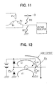
- the DC bias voltage becomes lower than a half of the terminal voltage of the vehicle battery, in other words, if the contact resistance R1 is larger than the contact resistance R2, the voltage Px or Pz of the X-phase or Z-phase winding alternately changes, with the DC bias voltage applied to the Y-phase winding being the center of the amplitude. If the voltage of the bias voltage is lower than a half of the battery terminal voltage, the phase voltages Px and Pz become the ground voltage faster than they become the battery terminal voltage. If the Z-phase voltage Pz becomes the ground voltage, a diode connected to the Z-phase winding passes signal current i1, so that the signal voltage becomes higher than the bias voltage. If the phase voltage Px becomes the ground voltage, a diode connected to the X-phase winding, likewise, passes signal current, as shown in Fig. 13A.
- the phase voltage Px or Pz alternately changes, with the bias voltage being the center of the amplitude. If the bias voltage is higher than a half of the battery terminal voltage, the phase voltages Px and Pz become the battery terminal voltage faster than they become the ground voltage. If the phase voltage Px becomes the battery terminal voltage, a diode connected to the X-phase winding passes signal current i2, so that the signal voltage becomes lower than the bias voltage, as shown in Fig. 14A.
- the bias voltage applied to the Y-phase winding becomes as high as a half of the battery terminal voltage due to leak current, it takes the longest time for the phase voltages Px and Pz of the X-phase and Y-phase windings to become 0 V or the battery terminal voltage. That is, if an amount of the leak current is very large, it takes a long time to generate the rotation signal to be detected.
- JP-A-3-215200 and PCT National Publication 8-503308 disclose control circuits in which terminal voltages of two phase windings are detected to thereby detect leak current.
- the present invention is to provide a voltage regulator of a vehicle AC generator that can surely detect a voltage signal from a terminal of a multi-phase armature winding.
- a voltage regulator of a vehicle AC generator includes means for detecting phase voltage of an armature winding, and a comparator for comparing phase voltage with a variable threshold level signal that varies according to the phase voltage. Even if leak current takes place and DC bias voltage is applied to the armature winding, a binary pulse signal can be surely formed so that the start of the rotation can be surely detected without delay. Accordingly, no exclusive signal line for detecting turning-on of a key switch is necessary.
- a pulse detecting means for detecting the number of the pulses of the output signal of the comparator or frequency thereof may be provided.
- the AC generator is operated if the pulse detecting means detects the number or frequency to be the same as or larger than a predetermined level. Therefore, the signal can be processed digitally at a high speed, so that the rotation can be detected without delay by a compact integrated circuit.
- the variable threshold level may be an electric signal that corresponds to one of the maximum voltage and the minimum voltage of the phase voltage.
- the variable threshold level can be formed by a positive peak hold circuit or a negative peak hold circuit.
- the variable threshold level signal may be an electric signal that corresponds to any value between the maximum voltage and the minimum voltage of the phase voltage.
- the variable threshold value signal can be formed by combining a positive or negative peak hold circuit and a voltage dividing resistors. Further, the DC bias voltage due to the leak current can be detected at any case.
- the variable threshold level signal may cross the phase voltage twice in a cycle of the phase voltage while the rotor is rotating. Therefore, the digitalized binary output pulse signal of the comparator can be surely formed.
- the variable threshold level signal may be a signal corresponds to a mean value of the phase voltage. Therefore, the variable threshold value signal can be formed easily by an integration circuit or the like.
- the frequency of the output pulse of the comparator may be equal to the frequency of the phase voltage. Therefore, the frequency of the phase voltage, which is caused by rotation of the rotor, can be accurately detected. In other words, the rotation speed of the rotor can be accurately detected.
- the voltage regulator may further includes a second comparator for comparing the phase voltage with a reference value, and the field current is supplied to the field coil for a predetermined period to increase the phase voltage when the second comparator reverses the output signal thereof.
- the signal is amplified by supplying field current to have a voltage level sufficient to be detected.
- the phase voltage detecting means may include a first resistor connected between the armature winding and the negative terminal of a vehicle battery, a second resistor that has much lower resistance than the first resistor and connected, together with a switching means, in parallel with the first resistor. If the switching means is closed especially in a case that leak current flows in the phase winding whose terminal voltage is detected as the rotation signal, the terminal voltage can be lowered. Therefore, the delay time until a signal is increased to an amount to be detected can be reduced.
- the switching means is opened. Therefore, power generated in the armature winding is prevented from being wasted by the second resistor.
- the switching means may be a MOSFET that is easy to mount in a circuit. Moreover, the signal current can be supplied not only from the winding to the negative terminal of the battery, but also from the negative terminal of the battery to the winding. Therefore, the rotation can be detected even if the contact resistance varies widely.
- the predetermined period may be longer than a period during which the field coil is supplied with field current so that the output voltage of the armature winding becomes as high as about a half of a nominal vehicle battery voltage. That is, the field current is supplied until the signal is generated even in the case that leak current takes place and the output voltage of the armature winding is fixed to be as high as a half of a nominal voltage of the vehicle battery. Therefore, the signal can be surely detected. Accordingly, the rotation of the rotor can be detected whenever any leak current flows.
- the voltage regulator may cut the field current for a period after the field current is supplied to the field coil and before the field current is supplied to the field coil for a next period. Therefore, the field current is prevented from being continuously supplied as long as the leak current flows.
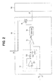
- FIG. 1 shows an alternator 1, through Fig. 4.
- the alternator 1 is connected to a vehicle battery 2.
- the alternator 1 is comprised of a three-phase armature winding 3, a full-wave rectifier unit 4 connected to respective phase windings of the three-phase armature winding 3, a field coil 5 mounted in a rotary magnetic pole core (not shown) for providing a rotary magnetic field to be supplied to the respective phase windings, and a voltage regulator 6 for controlling the output voltage of the armature winding 4 at a prescribed voltage level by controlling field current supplied to the field coil 5.
- the voltage regulator 6 is comprised of a power transistor 61 which switches on and off the field current supplied to the field coil 5, a flywheel diode 62 for passing the field current when the power transistor 61 is turned off, a voltage control circuit 63, a main power circuit 64, and a sub-power circuit 65.
- the voltage control circuit 63 monitors the output voltage of the full-wave rectifier unit 4 and generating a signal that drives the power transistor 61 so that the output voltage can be controlled at a prescribed level.
- the main power circuit 64 supplies power to the voltage control circuit 63 to keep the operation thereof.
- the sub-power circuit 65 detects a terminal voltage Py of a Y-phase winding of the armature winding 3 and generates a signal for driving the main power circuit when it detects rotation of the rotor.
- the sub-power circuit 65 is comprised of an input terminal 71 to which the phase voltage Py of the Y-phase winding is applied, an integration circuit 72 for providing the mean value of the Y-phase voltage Py, a voltage follower 721, a resistor 722 and a capacitor 723, a comparator 73, a counter circuit 74 and an analog switch 75.
- the comparator 73 compares the phase voltage Py with the output signal of the integration circuit 72 and provides a binary pulse signal.
- the counter circuit 74 counts the number of the pulses of the pulse signal of the comparator 73 and reverses when the number of the pulses becomes a predetermined number.
- the analog switch 75 supplies electric power to the main power circuit 64.
- the sub-power circuit 65 provides a mean value of the Y-phase voltage at the integration circuit 72. Both the Y-phase voltage and the mean value thereof are inputted to the comparator 73, so that the comparator provides an output pulse signal.
- the number of pulses of the output pulse signal depends on the rotation speed. Therefore, if the rotation speed is high, the number of pulses per unit time becomes high. On the other hand, if the rotation speed is low, the number of the pulses per unit time is low. That is, the rotation speed of the rotor can be detected by counting the pulses. If the number of the pulses is larger than a predetermined number, it is judged that the rotor rotates at a normal operation speed. Then the counter circuit reverses, so that the analog switch is closed to maintain operation of the main power circuit.
- the comparator 73 can compares both the input signals thereof and provide the output pulse signal Vco whenever the phase signal Py is applied to the terminal 71, as shown in Figs. 3A and 3B.
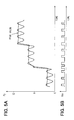
- a variation 65a of the sub-power circuit 65 accocrding to the first embodiment of the invention is described with reference to Fig. 4 and Figs. 5A and 5B.
- This sub-power circuit 65a has a peak hold circuit 76 for detecting the peak values of the Y-phase voltage instead of the integration circuit 72.
- the peak hold circuit 76 which has a time constant of a CR circuit, can not detect a complete envelope of the phase voltage. In other words, because of this feature, the Y-phase voltage Py and the output signal of the peak hold circuit 76 cross each other, so that the comparator can provide the pulse signal Vco at the output terminal thereof, as shown in Figs. 5A and 5B. Other operation is the same as the operation of the first embodiment.
- this voltage signal is divided into a suitable value to provide a medium threshold value between the peak value and the minimum value.
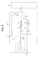
- a voltage regulator according to a second embodiment of the invention is described with reference to Fig. 6.
- a sub-power circuit 65b of the voltage regulator 6 according to the second embodiment is equipped with a series circuit of a second comparator 81 and a timer circuit 82.
- the Y-phase voltage of the Y-phase winding is compared with a voltage V1.
- the analog switch 75 is turned on to drive the power circuit 64 for a limited short period. If the rotor of the alternator 1 rotates at this moment, the phase voltage Py of the Y-phase winding rises up instantly because the field current is supplied to the field coil, so that generation can be detected very easily. If the number of the pulses Vco supplied from the comparator 73 is larger than a predetermined value, the AC generator immediately starts normal generation.
- the comparator 73 does not provide the pulse signal, and the analog switch turns off after such short period. If there is a certain interval before the next input signal applied to the comparator 81, the vehicle battery can be prevented from discharging.
- the time lag of the signal caused by the leak current can be eliminated by supplying the field current thereby to amplify the signal.
- the main power source is prevented from operating without control.
- a voltage regulator 6 according to a third embodiment of the invention is described with reference to Fig. 7.
- a first resistor 84 is connected between the terminal of a sub-power circuit 65c and the ground, and a second resistor 85, which has a much smaller resistance R3 than the first resistor, is connected in parallel with the first resistor 84.
- a switching element 86 is connected between the second resistor 85 and the ground.
- the resistance of the first resistor 84 is about 100 times as many as, or more than, the resistance of the second resistor 85.
- the sub-power circuit 65c has a third comparator 87 that compares the Y-phase voltage with a second voltage level V2 that is higher than the first voltage level V1.
- the switching element 86 is turned on until the third comparator 87 reverses.
- the third comparator 87 does not reverse until the Y-phase voltage becomes as high as the second voltage level V2. When it does not reverse, the switching element 86 is turned on. If leak current flows, the DC bias voltage of the Y-phase winding is reduced from a high level expressed by Vbatt ⁇ R2 /(R1 + R2) to a low level expressed by Vbatt ⁇ R3 / (R1 + R3), since the resistor having much smaller resistance R3 than R2 is connected. As stated before, if the DC bias voltage is low, the detection delay is improved since the time lag of the signal generated when the rotor rotates becomes shorter.
- the switch 86 is turned off immediately after the terminal voltage of the Y-phase winding reaches V2.
- phase voltage Py field current is supplied for a period so that the output voltage of the armature winding becomes as high as a half of the battery terminal voltage.
- the input terminal of the sub-power circuit 65c, to which the phase voltage Py is applied is raised by the leak current to be higher than the first voltage level V1.
- the field current may be otherwise supplied again, and the battery power may be wasted due to discharge. However, this is prevented by providing an interval before the next Py-phase voltage is detected.
Applications Claiming Priority (4)
| Application Number | Priority Date | Filing Date | Title |
|---|---|---|---|
| JP2000239918 | 2000-08-08 | ||
| JP2000239918 | 2000-08-08 | ||
| JP2001144937 | 2001-05-15 | ||
| JP2001144937A JP4186432B2 (ja) | 2000-08-08 | 2001-05-15 | 車両用交流発電機の電圧制御装置 |
Publications (2)
| Publication Number | Publication Date |
|---|---|
| EP1180841A1 true EP1180841A1 (fr) | 2002-02-20 |
| EP1180841B1 EP1180841B1 (fr) | 2004-04-21 |
Family
ID=26597553
Family Applications (1)
| Application Number | Title | Priority Date | Filing Date |
|---|---|---|---|
| EP01117533A Expired - Lifetime EP1180841B1 (fr) | 2000-08-08 | 2001-07-20 | Régulateur de tension d'un alternateur de véhicule |
Country Status (4)
| Country | Link |
|---|---|
| US (1) | US6621251B2 (fr) |
| EP (1) | EP1180841B1 (fr) |
| JP (1) | JP4186432B2 (fr) |
| DE (1) | DE60102873T2 (fr) |
Cited By (3)
| Publication number | Priority date | Publication date | Assignee | Title |
|---|---|---|---|---|
| WO2010049305A2 (fr) | 2008-10-27 | 2010-05-06 | Robert Bosch Gmbh | Dispositif pour détecter une modification d'un signal de sortie d'une génératrice de véhicule |
| IT201900002959A1 (it) * | 2019-02-28 | 2020-08-28 | St Microelectronics Srl | Procedimento per la rilevazione di segnali, circuito, dispositivo e sistema corrispondenti |
| EP4078205A4 (fr) * | 2019-12-17 | 2024-01-17 | Scania Cv Ab | Procédé et agencement pour déterminer la fonctionnalité d'un alternateur |
Families Citing this family (13)
| Publication number | Priority date | Publication date | Assignee | Title |
|---|---|---|---|---|
| JP4438261B2 (ja) * | 2001-08-31 | 2010-03-24 | 株式会社デンソー | 車両用交流発電機 |
| US6750635B2 (en) * | 2001-09-24 | 2004-06-15 | Delphi Technologies, Inc. | Apparatus and method for comparing output signals indicative of engine rotational speed and/or generator rotational speed |
| JP3932104B2 (ja) * | 2002-03-20 | 2007-06-20 | 株式会社デンソー | 車両用交流発電機装置及びその製造方法 |
| JP4450613B2 (ja) * | 2003-12-17 | 2010-04-14 | 三菱電機株式会社 | 車両用交流発電機の制御装置 |
| US7564224B2 (en) | 2005-11-08 | 2009-07-21 | Denso Corporation | Power-generator control method and apparatus using externally applied periodic signal |
| US20070273205A1 (en) * | 2006-05-22 | 2007-11-29 | Denso Corporation | Communication system for use in data communications between power generator and external unit |
| JP4270279B2 (ja) * | 2007-01-05 | 2009-05-27 | 株式会社デンソー | 車両用交流発電機の制御装置 |
| JP4823078B2 (ja) * | 2007-01-09 | 2011-11-24 | ヤマハモーターエレクトロニクス株式会社 | 車両における充電装置 |
| US20130113457A1 (en) * | 2011-11-04 | 2013-05-09 | Kohler Co. | Method of sensing generator speed |
| DE102012013405A1 (de) * | 2012-07-05 | 2014-01-09 | Audi Ag | Diagnoseeinrichtung zur Überprüfung einer Steuersignalleitung |
| US9590548B2 (en) * | 2014-09-25 | 2017-03-07 | Nxp Usa, Inc. | Method and apparatus for regulating an output voltage of an alternator |
| JP6211120B2 (ja) * | 2016-03-28 | 2017-10-11 | 三菱電機株式会社 | 相電圧検出回路および発電制御装置 |
| KR102343295B1 (ko) * | 2019-11-05 | 2021-12-24 | 현대모비스 주식회사 | 누설전류 검출 기능을 구비한 bms 반도체 장치 및 그것의 누설전류 검출 방법 |
Citations (5)
| Publication number | Priority date | Publication date | Assignee | Title |
|---|---|---|---|---|
| US4297631A (en) * | 1979-03-16 | 1981-10-27 | Lucas Industries Limited | Battery charging systems for road vehicles |
| EP0510527A1 (fr) * | 1991-04-22 | 1992-10-28 | MAGNETI MARELLI S.p.A. | Circuit de surveillance pour un système de recharge de la batterie d'un véhicule à moteur |
| US5376876A (en) * | 1992-06-25 | 1994-12-27 | Motorola, Inc. | Phase winding detector and alternator charging system |
| US5449999A (en) * | 1994-06-13 | 1995-09-12 | Motorola, Inc. | Rectifier leakage compensated alternator phase detection system and method |
| WO1999007064A1 (fr) * | 1997-07-31 | 1999-02-11 | Robert Bosch Gmbh | Regulateur avec evaluation de tension de phase pour un generateur de courant triphase |
Family Cites Families (28)
| Publication number | Priority date | Publication date | Assignee | Title |
|---|---|---|---|---|
| US4143289A (en) | 1976-12-14 | 1979-03-06 | Progressive Electronics, Inc. | Rotational field sensor |
| US4495450A (en) * | 1982-12-29 | 1985-01-22 | Sanyo Electric Co., Ltd. | Control device for brushless motor |
| US4641066A (en) * | 1984-10-04 | 1987-02-03 | Nippondenso Co., Ltd. | Control apparatus for brushless motor |
| US4585982A (en) * | 1984-12-10 | 1986-04-29 | General Electric Company | Third harmonic auxiliary impulse commutation inverter with means for precharging commutation capacitor |
| JPS6284399U (fr) * | 1985-11-18 | 1987-05-29 | ||
| US4743777A (en) * | 1986-03-07 | 1988-05-10 | Westinghouse Electric Corp. | Starter generator system with two stator exciter windings |
| JPS62191392U (fr) * | 1986-05-28 | 1987-12-05 | ||
| US4730097A (en) * | 1986-08-15 | 1988-03-08 | General Motors Corporation | Dual mode windshield heater control |
| US4743815A (en) * | 1987-09-01 | 1988-05-10 | Emerson Electric Co. | Brushless permanent magnet motor system |
| CA2003191A1 (fr) * | 1988-11-21 | 1990-05-21 | Shigeki Tezuka | Systeme d'alimentation en energie electrique pour automobile |
| FR2649797B1 (fr) | 1989-07-11 | 1991-10-31 | Valeo Equip Electr Moteur | Circuit de detection du signal phase alternateur polyphase de controle d'un regulateur de charge de batterie de vehicule automobile et son utilisation |
| US5097195A (en) * | 1989-11-27 | 1992-03-17 | Sundstrand Corporation | AC exciter for VSCF starter/generator |
| JP2649291B2 (ja) | 1991-05-22 | 1997-09-03 | 東洋電産株式会社 | 車両用交流発電機 |
| JP3283042B2 (ja) * | 1991-07-12 | 2002-05-20 | 本田技研工業株式会社 | 携帯用電源装置 |
| JP3363170B2 (ja) * | 1992-02-10 | 2003-01-08 | 本田技研工業株式会社 | インバータ制御式発電機 |
| JPH06284596A (ja) | 1993-03-25 | 1994-10-07 | Mitsubishi Electric Corp | 車両用交流発電機の電圧調整器 |
| JPH06284598A (ja) | 1993-03-29 | 1994-10-07 | Sawafuji Electric Co Ltd | 車両用充電発電装置 |
| US5495162A (en) * | 1993-05-12 | 1996-02-27 | Sundstrand Corporation | Position-and-velocity sensorless control for starter generator electrical system using generator back-EMF voltage |
| DE4327485B4 (de) | 1993-08-16 | 2005-10-27 | Robert Bosch Gmbh | Schaltungsanordnung zur Messung der Drehzahl eines Generators |
| US5345156A (en) * | 1993-12-30 | 1994-09-06 | Whirlpool Corporation | Control for high speed operation of brushless permanent magnet motor |
| JP2000050696A (ja) * | 1998-08-03 | 2000-02-18 | Sawafuji Electric Co Ltd | 発動発電機用自動電圧調整装置 |
| US6215261B1 (en) * | 1999-05-21 | 2001-04-10 | General Electric Company | Application specific integrated circuit for controlling power devices for commutating a motor based on the back emf of motor |
| GB0004018D0 (en) * | 2000-02-22 | 2000-04-12 | Lucas Industries Ltd | Control circuit for electrical generator |
| JP3866013B2 (ja) * | 2000-06-07 | 2007-01-10 | 三菱電機株式会社 | オルタネータの電圧制御装置 |
| JP4224932B2 (ja) * | 2000-08-07 | 2009-02-18 | 株式会社デンソー | 車両用交流発電機の電圧制御装置 |
| JP3519048B2 (ja) * | 2000-10-18 | 2004-04-12 | 三菱電機株式会社 | 車両用交流発電機の電圧制御装置 |
| US6528973B2 (en) * | 2001-01-22 | 2003-03-04 | Robert Fury | Voltage-limiting regulator for use with an AC generator having DC-excited fields |
| US6531850B1 (en) * | 2001-08-20 | 2003-03-11 | Deere & Company | Load controller utilizing alternator field excitation |
-
2001
- 2001-05-15 JP JP2001144937A patent/JP4186432B2/ja not_active Expired - Fee Related
- 2001-07-20 EP EP01117533A patent/EP1180841B1/fr not_active Expired - Lifetime
- 2001-07-20 DE DE60102873T patent/DE60102873T2/de not_active Expired - Lifetime
- 2001-08-07 US US09/922,690 patent/US6621251B2/en not_active Expired - Fee Related
Patent Citations (5)
| Publication number | Priority date | Publication date | Assignee | Title |
|---|---|---|---|---|
| US4297631A (en) * | 1979-03-16 | 1981-10-27 | Lucas Industries Limited | Battery charging systems for road vehicles |
| EP0510527A1 (fr) * | 1991-04-22 | 1992-10-28 | MAGNETI MARELLI S.p.A. | Circuit de surveillance pour un système de recharge de la batterie d'un véhicule à moteur |
| US5376876A (en) * | 1992-06-25 | 1994-12-27 | Motorola, Inc. | Phase winding detector and alternator charging system |
| US5449999A (en) * | 1994-06-13 | 1995-09-12 | Motorola, Inc. | Rectifier leakage compensated alternator phase detection system and method |
| WO1999007064A1 (fr) * | 1997-07-31 | 1999-02-11 | Robert Bosch Gmbh | Regulateur avec evaluation de tension de phase pour un generateur de courant triphase |
Cited By (7)
| Publication number | Priority date | Publication date | Assignee | Title |
|---|---|---|---|---|
| WO2010049305A2 (fr) | 2008-10-27 | 2010-05-06 | Robert Bosch Gmbh | Dispositif pour détecter une modification d'un signal de sortie d'une génératrice de véhicule |
| WO2010049305A3 (fr) * | 2008-10-27 | 2011-05-05 | Robert Bosch Gmbh | Dispositif pour détecter une modification d'un signal de sortie d'une génératrice de véhicule |
| US8692522B2 (en) | 2008-10-27 | 2014-04-08 | Robert Bosch Gmbh | Device for detecting a change in a generator output signal of a vehicle generator |
| IT201900002959A1 (it) * | 2019-02-28 | 2020-08-28 | St Microelectronics Srl | Procedimento per la rilevazione di segnali, circuito, dispositivo e sistema corrispondenti |
| EP3702795A1 (fr) * | 2019-02-28 | 2020-09-02 | STMicroelectronics Srl | Procédé de détection de signal, circuit, dispositif et système correspondants |
| US11418139B2 (en) | 2019-02-28 | 2022-08-16 | Stmicroelectronics S.R.L. | Signal detection method, corresponding circuit, device and system |
| EP4078205A4 (fr) * | 2019-12-17 | 2024-01-17 | Scania Cv Ab | Procédé et agencement pour déterminer la fonctionnalité d'un alternateur |
Also Published As
| Publication number | Publication date |
|---|---|
| JP2002125398A (ja) | 2002-04-26 |
| US20020021111A1 (en) | 2002-02-21 |
| DE60102873T2 (de) | 2005-03-31 |
| EP1180841B1 (fr) | 2004-04-21 |
| US6621251B2 (en) | 2003-09-16 |
| JP4186432B2 (ja) | 2008-11-26 |
| DE60102873D1 (de) | 2004-05-27 |
Similar Documents
| Publication | Publication Date | Title |
|---|---|---|
| EP1180841B1 (fr) | Régulateur de tension d'un alternateur de véhicule | |
| US7843675B2 (en) | Overcurrent protection circuit, load driving device, motor driving device, electric appliance, power supply device | |
| US6420855B2 (en) | Vehicular ac generator having voltage control unit | |
| US6777898B2 (en) | Methods and apparatus for maintaining synchronization of a polyphase motor during power interruptions | |
| KR100486838B1 (ko) | 회전 개시 검출을 위한 검출기를 구비한 차량용 교류발전기 | |
| EP1258980B1 (fr) | Circuit d'alimentation et méthode de protection contre surtension sur une ligne d'alimentation pendant l'entraínement d'un moteur à cc | |
| US3887844A (en) | Overcurrent protection circuit for a brushless direct current motor | |
| JP4200672B2 (ja) | 車両用発電制御装置 | |
| KR101916795B1 (ko) | 스위치드 릴럭턴스 모터를 갖는 모터 시스템 및 그것의 동작 방법 | |
| US6603289B2 (en) | Vehicle alternator control device and method | |
| US5317244A (en) | Motor control unit provided with anti-burning device | |
| JP4192427B2 (ja) | 車両用発電制御装置 | |
| TW202010206A (zh) | 馬達斷電剎車系統及方法 | |
| JP2004135374A (ja) | 単相ブラシレスモータの駆動装置 | |
| JPH09166610A (ja) | モータの回転異常検出装置 | |
| JP2538977B2 (ja) | モ―タの焼損防止装置を備えた駆動装置 | |
| JP4273874B2 (ja) | コンデンサ放電式内燃機関用点火装置 | |
| JPH07118941B2 (ja) | ブラシレスモ−タのコイル焼損防止装置 | |
| JPH10117494A (ja) | 電流制限装置付直流電動機の制御回路 | |
| JPS59139847A (ja) | 回転子巻線を有する直流ブラシレスモ−タ | |
| JPH01164289A (ja) | 1相の半導体電動機 | |
| JPH08322281A (ja) | 直流ブラシレスモータの保護装置 | |
| JPH09163786A (ja) | モータ制御回路 | |
| JPH01248988A (ja) | 一相の半導体電動機 | |
| JPH0530781A (ja) | ブラシレスモータの制御回路 |
Legal Events
| Date | Code | Title | Description |
|---|---|---|---|
| PUAI | Public reference made under article 153(3) epc to a published international application that has entered the european phase |
Free format text: ORIGINAL CODE: 0009012 |
|
| AK | Designated contracting states |
Kind code of ref document: A1 Designated state(s): DE FR IT Kind code of ref document: A1 Designated state(s): AT BE CH CY DE DK ES FI FR GB GR IE IT LI LU MC NL PT SE TR |
|
| AX | Request for extension of the european patent |
Free format text: AL;LT;LV;MK;RO;SI |
|
| 17P | Request for examination filed |
Effective date: 20020308 |
|
| 17Q | First examination report despatched |
Effective date: 20020909 |
|
| AKX | Designation fees paid |
Free format text: DE FR IT |
|
| GRAP | Despatch of communication of intention to grant a patent |
Free format text: ORIGINAL CODE: EPIDOSNIGR1 |
|
| GRAS | Grant fee paid |
Free format text: ORIGINAL CODE: EPIDOSNIGR3 |
|
| GRAA | (expected) grant |
Free format text: ORIGINAL CODE: 0009210 |
|
| AK | Designated contracting states |
Kind code of ref document: B1 Designated state(s): DE FR IT |
|
| REG | Reference to a national code |
Ref country code: IE Ref legal event code: FG4D |
|
| REF | Corresponds to: |
Ref document number: 60102873 Country of ref document: DE Date of ref document: 20040527 Kind code of ref document: P |
|
| ET | Fr: translation filed | ||
| PLBE | No opposition filed within time limit |
Free format text: ORIGINAL CODE: 0009261 |
|
| STAA | Information on the status of an ep patent application or granted ep patent |
Free format text: STATUS: NO OPPOSITION FILED WITHIN TIME LIMIT |
|
| 26N | No opposition filed |
Effective date: 20050124 |
|
| REG | Reference to a national code |
Ref country code: IE Ref legal event code: MM4A |
|
| PGFP | Annual fee paid to national office [announced via postgrant information from national office to epo] |
Ref country code: DE Payment date: 20130722 Year of fee payment: 13 |
|
| PGFP | Annual fee paid to national office [announced via postgrant information from national office to epo] |
Ref country code: FR Payment date: 20130722 Year of fee payment: 13 |
|
| PGFP | Annual fee paid to national office [announced via postgrant information from national office to epo] |
Ref country code: IT Payment date: 20130729 Year of fee payment: 13 |
|
| REG | Reference to a national code |
Ref country code: DE Ref legal event code: R119 Ref document number: 60102873 Country of ref document: DE |
|
| REG | Reference to a national code |
Ref country code: FR Ref legal event code: ST Effective date: 20150331 |
|
| PG25 | Lapsed in a contracting state [announced via postgrant information from national office to epo] |
Ref country code: IT Free format text: LAPSE BECAUSE OF NON-PAYMENT OF DUE FEES Effective date: 20140720 Ref country code: DE Free format text: LAPSE BECAUSE OF NON-PAYMENT OF DUE FEES Effective date: 20150203 |
|
| REG | Reference to a national code |
Ref country code: DE Ref legal event code: R119 Ref document number: 60102873 Country of ref document: DE Effective date: 20150203 |
|
| PG25 | Lapsed in a contracting state [announced via postgrant information from national office to epo] |
Ref country code: FR Free format text: LAPSE BECAUSE OF NON-PAYMENT OF DUE FEES Effective date: 20140731 |