EP1178345B1 - Spektroskopische Anordnung in einem konfokalen Mikroskop - Google Patents
Spektroskopische Anordnung in einem konfokalen Mikroskop Download PDFInfo
- Publication number
- EP1178345B1 EP1178345B1 EP01117981A EP01117981A EP1178345B1 EP 1178345 B1 EP1178345 B1 EP 1178345B1 EP 01117981 A EP01117981 A EP 01117981A EP 01117981 A EP01117981 A EP 01117981A EP 1178345 B1 EP1178345 B1 EP 1178345B1
- Authority
- EP
- European Patent Office
- Prior art keywords
- detection device
- raster
- light beam
- microscope according
- spectral
- Prior art date
- Legal status (The legal status is an assumption and is not a legal conclusion. Google has not performed a legal analysis and makes no representation as to the accuracy of the status listed.)
- Expired - Lifetime
Links
- 238000001514 detection method Methods 0.000 claims description 69
- 230000003595 spectral effect Effects 0.000 claims description 60
- 230000003287 optical effect Effects 0.000 claims description 23
- 230000005540 biological transmission Effects 0.000 claims description 5
- 238000006073 displacement reaction Methods 0.000 claims description 4
- 230000001360 synchronised effect Effects 0.000 claims description 4
- 238000000354 decomposition reaction Methods 0.000 description 14
- 238000000034 method Methods 0.000 description 6
- 238000005286 illumination Methods 0.000 description 3
- 238000012216 screening Methods 0.000 description 3
- 230000008878 coupling Effects 0.000 description 2
- 238000010168 coupling process Methods 0.000 description 2
- 238000005859 coupling reaction Methods 0.000 description 2
- 238000004519 manufacturing process Methods 0.000 description 2
- 210000001747 pupil Anatomy 0.000 description 2
- 238000011144 upstream manufacturing Methods 0.000 description 2
- 229910000831 Steel Inorganic materials 0.000 description 1
- 238000013461 design Methods 0.000 description 1
- 238000011161 development Methods 0.000 description 1
- 230000018109 developmental process Effects 0.000 description 1
- 239000006185 dispersion Substances 0.000 description 1
- 230000005284 excitation Effects 0.000 description 1
- 239000007850 fluorescent dye Substances 0.000 description 1
- 230000002093 peripheral effect Effects 0.000 description 1
- 238000004621 scanning probe microscopy Methods 0.000 description 1
- 239000010959 steel Substances 0.000 description 1
- 238000012546 transfer Methods 0.000 description 1
Images
Classifications
-
- G—PHYSICS
- G01—MEASURING; TESTING
- G01J—MEASUREMENT OF INTENSITY, VELOCITY, SPECTRAL CONTENT, POLARISATION, PHASE OR PULSE CHARACTERISTICS OF INFRARED, VISIBLE OR ULTRAVIOLET LIGHT; COLORIMETRY; RADIATION PYROMETRY
- G01J3/00—Spectrometry; Spectrophotometry; Monochromators; Measuring colours
- G01J3/28—Investigating the spectrum
- G01J3/30—Measuring the intensity of spectral lines directly on the spectrum itself
- G01J3/32—Investigating bands of a spectrum in sequence by a single detector
-
- G—PHYSICS
- G01—MEASURING; TESTING
- G01J—MEASUREMENT OF INTENSITY, VELOCITY, SPECTRAL CONTENT, POLARISATION, PHASE OR PULSE CHARACTERISTICS OF INFRARED, VISIBLE OR ULTRAVIOLET LIGHT; COLORIMETRY; RADIATION PYROMETRY
- G01J3/00—Spectrometry; Spectrophotometry; Monochromators; Measuring colours
- G01J3/12—Generating the spectrum; Monochromators
- G01J3/14—Generating the spectrum; Monochromators using refracting elements, e.g. prisms
-
- G—PHYSICS
- G02—OPTICS
- G02B—OPTICAL ELEMENTS, SYSTEMS OR APPARATUS
- G02B21/00—Microscopes
- G02B21/0004—Microscopes specially adapted for specific applications
- G02B21/002—Scanning microscopes
- G02B21/0024—Confocal scanning microscopes (CSOMs) or confocal "macroscopes"; Accessories which are not restricted to use with CSOMs, e.g. sample holders
- G02B21/0036—Scanning details, e.g. scanning stages
- G02B21/0048—Scanning details, e.g. scanning stages scanning mirrors, e.g. rotating or galvanomirrors, MEMS mirrors
-
- G—PHYSICS
- G02—OPTICS
- G02B—OPTICAL ELEMENTS, SYSTEMS OR APPARATUS
- G02B21/00—Microscopes
- G02B21/0004—Microscopes specially adapted for specific applications
- G02B21/002—Scanning microscopes
- G02B21/0024—Confocal scanning microscopes (CSOMs) or confocal "macroscopes"; Accessories which are not restricted to use with CSOMs, e.g. sample holders
- G02B21/0052—Optical details of the image generation
- G02B21/0064—Optical details of the image generation multi-spectral or wavelength-selective arrangements, e.g. wavelength fan-out, chromatic profiling
-
- G—PHYSICS
- G02—OPTICS
- G02B—OPTICAL ELEMENTS, SYSTEMS OR APPARATUS
- G02B21/00—Microscopes
- G02B21/0004—Microscopes specially adapted for specific applications
- G02B21/002—Scanning microscopes
- G02B21/0024—Confocal scanning microscopes (CSOMs) or confocal "macroscopes"; Accessories which are not restricted to use with CSOMs, e.g. sample holders
- G02B21/008—Details of detection or image processing, including general computer control
Definitions
- the present invention relates to a confocal scanning microscope after the generic term of Patent claim 1.
- the further mirror shutter assembly may be a part of the first mirror shutter assembly reflected spectrally fanned light pass through the is detected with another detector. The remaining part will be with the other one Mirror aperture device to a third detector reflects, if necessary a further mirror aperture arrangement is arranged upstream.
- the known optical arrangements use for the detection of various Spectral ranges multiple detection channels. Each detection channel is common equipped with its own detector, which is sometimes considerable Costs associated. With the known optical arrangements, it is also possible simultaneously detect multiple spectral ranges, but is a detection numerous narrow-band spectral ranges with the known arrangements simultaneously not readily possible. Especially if the entire spectral range from 500 nm to 800 nm in 5 nm increments, for example a mechanical adjustment of the variably arranged mirror covers required which takes a relatively long time.
- the present invention is therefore based on the object, an optical arrangement of the generic type to specify and further educate, the one from detecting spectral range of several narrowband spectral ranges scan as far as possible and detect them in variably adjustable steps can. Furthermore, a fast and variable spectral detection should be possible which is at the same time economically feasible.
- the method of the generic type of the invention solves the above Task by the features of claim 1. Thereafter are to influence the to be detected spectral range of the spectrally dispersed light beam and the detection device relative to each other in their position changeable.
- a fast and variable spectral detection can be achieved by a relative change in position, and Although without ever moving at least one mirror aperture mechanically.
- this relative change in position it is possible in an advantageous manner, the adjust the spectral detection range much faster than with a Spectral range change by the means for selecting the predeterminable range is possible, whereby the detection time is reduced.
- the detection time is reduced. For example it is in particular in the selection of a narrow-band spectral detection range of 5 nm possible due to the relative position change an extended Spectral range with this adjusted narrowband spectral range in increments of 5 nm each.
- the detection device comprises only one Detector.
- This detector could, for example, be a photomultiplier the use of a photodiode, in particular an avalanche photodiode, would also be possible. Due to the relative change in position of the spectrally dispersed light beam and the detection device can be in an advantageous Way to dispense with the use of multiple detectors, reflecting the manufacturing cost considerably reduced. Ultimately, not just two, three or saved four detectors, but also their sometimes complex power supply and readout devices with the corresponding peripherals. Furthermore further eliminates the complicated spatial arrangement of multiple detectors together with their means for selecting the predeterminable spectral range, so that in Further advantageously, the production is considerably simplified.
- the inventive relative position change between the spectrally decomposed Light beam and the detection device causes a change in the initial and / or end wavelength of the spectrally selected region. If, for example the spectrally split light beam laterally displaced relative to the detection device is, the detector "sees" after this shift a spectral range, which has a different initial and final wavelength.
- the dispersion property of the means for spectral decomposition remains smaller in this example the width of the spectral range to be detected is unchanged, since the position of the Means for selecting the predeterminable spectral range relative to the detector were not changed.
- the relative position change is at least a arranged in the beam path optical component rotated or shifted.
- at the optical component is preferably a mirror.
- the turning a mirror arranged in the optical beam path could be detected Tilt light bundles in the pupil of a lens collimating the light beam.
- the rotating mirror would have to be in the detection beam path of the collimating Lens upstream.
- the rotated or shifted optical component is in Detection beam path arranged in front of the means for spectral decomposition.
- the Tilting the light beam in the pupil of the collimating lens causes a lateral Displacement of the spectrally decomposed incident on the detection device Light beam.
- the relative position change takes place between the spectrally split light beam and the detection device by turning or shifting the means for spectral decomposition. Also this can the spectrally dispersed light beam is displaced relative to the detection device or to be changed.
- optical component or the means for spectral decomposition could also be rotated and be moved. This results then - depending on the arrangement the axis of rotation and the design of the displacement - a tilting of the optical component or the means for spectral decomposition.
- the rotation of the means for spectral decomposition and the above-mentioned optical Component could be done using a galvanometer. That too rotating component could be coupled directly to the galvanometer. Preferably it is fixed on the mechanical axis of rotation.
- the Rotation of the components to be rotated by the use of piezoelectric elements done. This rotation could be effected via a mechanical lever, wherein the lever, for example, extends radially relative to the axis of rotation and the piezoelectric element between a stationary housing part and the mechanical lever acts. in this connection is a rotation of the component in the two opposite directions of rotation Required, wherein the mechanical lever is coupled to the piezo element such the piezo element can both push and pull the lever.
- the relative position change between the spectrally dispersed light beam and the detection device done by a relative movement of the detection device.
- the Relative movement of the detection device either straight or on a sheet respectively.
- the means for selecting the predeterminable Spectral range - ie, for example, the slit diaphragm assembly - together with the Detector moves.
- the detection device in this case comprises the means for Select the predefinable area and the detector. If the relative movement over a distance smaller than the usable extent of the detector, could advantageously only the means for selecting the predefinable be moved spectral range.
- the relative position change takes place between the spectrally split light beam and the detection device by a Combined angle / position change of at least two optical components.
- a rotating Mirror with the relative movement of the detection device is an accelerated Detection possible with modified spectral detection setting. So could combines a arranged in the beam path optical component and the means for spectral disassembly and the detection device each have an angular and / or change position, the frequencies of the respective angle / position change can be in a fixed relationship to each other. For example, it turns the second component with twice the frequency of the first component and the detection device is at a threefold frequency of the rotational movement of the first Moving component.
- a means for spectral decomposition is a prism, a reflection or a transmission grating intended.
- the use of a prism for spectral decomposition has the advantage that the stray light components in a prism compared to a Lattice are smaller, so that a prism for spectral decomposition for the inventive Arrangement is preferred.
- a reflection or transmission grating would be preferable if the scattered light portions detector side a subordinate Play a role, but the means of spectral decomposition - so the grid - rotated or shifted due to the lower mass at a high frequency shall be.
- the relative position change between the spectrally split light beam and the detection device with the Scanning process of the confocal scanning microscope synchronized can be changed during the scanning process, which in particular Advantageously for each object point, for example, the spectral distribution of the fluorescent light emitted from the object point can.
- an object detail at different spectral detection settings repeated as long as each scanned until the entire to be detected Spectral range is detected. Only then will a next object section be scanned.
- An object section could be a point, a line, a straight line, a Area or a three-dimensional area.
- a line grid could be be configured such that the spectral detection range has a width of 5 nm.
- the total spectral range available for detection runs from 500 nm to 800 nm.
- the specifiable spectral detection range is now set at the beginning of line screening so that the detector is the spectral Range detected from 500 nm to 505 nm.
- the object scanned the first time is determined by the relative change in position of the object spectrally split light beam and the detection device to be detected spectral range from 505 nm to 510 nm detected by the detector becomes. It is envisaged that the same line of the object will be scanned so often is until the detection light of the predetermined spectral range of 5 nm completely detected up to the highest wavelength to be detected of 800 nm has been. This procedure is also with any arbitrarily shaped or curved Line of an object conceivable. Regarding the area is a rectangle or an arbitrary limited two-dimensional area provided.
- the synchronization of the relative position change between the spectrally decomposed Light beam and the detection device with the screening process of the confocal Raster microscope also advantageously includes the choice of in the Scanning microscope light wavelength to be coupled. For example, it is at the confocal fluorescence scanning microscopy conceivable that during the above Line raster matching the respective set spectral detection range Light of the corresponding excitation wavelength of the for this Spectral detection area in question fluorescent dye in the Scanning microscope is coupled.
- the coupling of the light of the corresponding Wavelength takes place here with an acousto-optical component, for example a AOTF (Acousto-Optical-Tunable-Filter) or AOBS (Acousto-Optical-Beam-Splitter), as is known for example from DE 199 06 757.
- a AOTF or AOBS it is possible to selectively light a specific wavelength in the coupling in a confocal scanning microscope, whereby also light of several wavelengths can be coupled simultaneously and the light output of the light of the respective wavelength with the AOTF or AOBS is controllable.
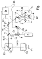
- the figure shows an optical arrangement for selection and detection of the spectral range a light beam 1 in a confocal scanning microscope, with a means 2 for the spectral decomposition of the light beam 1, with means 3 for selecting a predeterminable spectral range 4 and with a detection device 5.
- laser light 6 becomes the laser light source 7 with the help of an AOTF's 8 in the illumination beam path 9 of confocal scanning microscope coupled.
- the uncoupled laser light is absorbed by the jet trap 10.
- the coupled laser light 9 is at the Reflected dichroic beam splitter 11 to the beam deflector 12, wherein the Illumination light 9 in two substantially mutually perpendicular directions is distracted.
- the illumination light passes through the microscope optics 13 and Illuminates the schematically drawn fluorescent object 14.
- the fluorescence object 14 emitted fluorescent light 15 passes through the beam path in reverse Sequence up to the dichroic beam splitter 11.
- the fluorescent light 15 or 1 for further detection of the optical according to the invention Arrangement further processed.
- the detection device 5 comprises a single detector 20.
- the relative change in position between the spectrally dispersed light beam 19 and the detection device 5 causes a change in the initial and / or end wavelength of the spectrally selected area 4.
- the relative position change takes place by turning the mirror 21 arranged in the detection beam path 15.
- the mirror 21 is arranged in front of the means 2 for spectral decomposition.
- the rotation the mirror 21 takes place about the axis of rotation perpendicular to the plane of the drawing 26th
- the detection device 5 is along the direction 22nd moved in a straight line.
- the detector 5 and the means 3 for selecting become of the predeterminable area 4 moved together.
- a prism 2 is used for the spectral decomposition of the light beam 15.
- connection 23 By means of the connections 23, the relative change in position between the spectrally decomposed light steel 19 and the detection device 5 with the screening process synchronized by the confocal scanning microscope.
- the current position of Beam deflector 12 is the synchronization connection 23 the Transfer control computer 24 of the confocal scanning microscope, depending on the current beam position of the beam deflecting device 12, the mirror 21 and the Detection device 5 moves.
- the control computer 24 of the confocal scanning microscope is also connected via a connection 23 to the control device 25 of AOTF's 8 connected, allowing the choice of the coupled into the scanning microscope Wavelength also synchronous to the relative change in position between the spectrally dispersed light beam 19 and the detection device 5 is possible.
Landscapes
- Physics & Mathematics (AREA)
- Spectroscopy & Molecular Physics (AREA)
- General Physics & Mathematics (AREA)
- Chemical & Material Sciences (AREA)
- Analytical Chemistry (AREA)
- Optics & Photonics (AREA)
- Engineering & Computer Science (AREA)
- Computer Vision & Pattern Recognition (AREA)
- General Engineering & Computer Science (AREA)
- Microscoopes, Condenser (AREA)
- Investigating, Analyzing Materials By Fluorescence Or Luminescence (AREA)
- Diffracting Gratings Or Hologram Optical Elements (AREA)
- Spectrometry And Color Measurement (AREA)
- Investigating Or Analysing Materials By Optical Means (AREA)
- Mechanical Light Control Or Optical Switches (AREA)
Description
- Fig.
- eine schematische Darstellung eines Ausführungsbeispiels der erfindungsgemäßen optischen Anordnung.
Claims (13)
- Konfokales Rastermikroskop mit einer optischen Anordnung zur Selektion und Detektion des Lichts eines Spektralbereichs eines Lichtstrahls (1), wobei die optische Anordnung Mittel (2) zur spektralen Zerlegung des Lichtstrahls (1), Mittel (3) zum Selektieren eines vorgebbaren spektralen Bereichs (4) und eine Detektionsvorrichtung (5) umfasst und wobei zur Beeinflussung des zu detektierenden spektralen Bereichs (4, 18) der spektral zerlegte Lichtstrahl (19) und die Detektionsvorrichtung (5) relativ zueinander in ihrer Position veränderbar sind, dadurch gekennzeichnet, dass die relative Positionsänderung zwischen dem spektral zerlegten Lichtstrahl (19) und der Detektionsvorrichtung (5) durch eine Winkeländerung eines im Strahlengang vor einem Prisma oder Reflektionsgitter oder Transmissionsgitter angeordneten Spiegels (21) und einer simultanen lageänderung der Detektions vorrichtung (5) erfolgt.
- Rastermikroskop nach Anspruch 1, dadurch gekennzeichnet, dass das Prisma oder Reflektionsgitter oder Transmissionsgitter winkel veränderbar ist.
- Rastermikroskop nach Anspruch 1 oder 2, dadurch gekennzeichnet, dass die Detektionsvorrichtung (5) nur einen Detektor (20) umfasst.
- Rastermikroskop nach einem der Anspruch 1 bis 3, dadurch gekennzeichnet, dass die relative Positionsänderung zwischen dem spektral zerlegten Lichtstrahl (19) und der Detektionsvorrichtung (5) eine Veränderung der Anfangs- und/oder Endwellenlänge des spektral selektierten Bereichs (4) bewirkt.
- Rastermikroskop nach einem der Ansprüche 1 bis 4, dadurch gekennzeichnet, dass die relative Positionsänderung zwischen dem spektral zerlegten Lichtstrahl (19) und der Detektionsvorrichtung (5) durch Drehen und/oder Verschieben mindestens eines im Strahlengang (15) angeordneten optischen Bauteils, vorzugsweise eines Spiegels (21), erfolgt, wobei das optische Bauteil (21) vor dem Mittel (2) zur spektralen Zerlegung angeordnet sein kann.
- Rastermikroskop nach einem der Ansprüche 1 bis 5, dadurch gekennzeichnet, dass die relative Positionsänderung zwischen dem spektral zerlegten Lichtstrahl (19) und der Detektionsvorrichtung (5) durch Drehen und/oder Verschieben des Mittels (2) zur spektralen Zerlegung erfolgt.
- Rastermikroskop nach Anspruch 5 oder 6, dadurch gekennzeichnet, dass die Drehung unter Verwendung eines Galvanometers erfolgt, wobei das zu drehende Bauteil (21, 2) direkt an dem Galvanometer, vorzugsweise auf dessen mechanischer Drehachse befestigt, gekoppelt sein kann.
- Rastermikroskop nach Anspruch 5 oder 6, dadurch gekennzeichnet, dass die Drehung durch den Einsatz von Piezoelementen erfolgt, wobei ein Piezoelement die Drehung über einen mechanischen Hebel bewirken kann.
- Rastermikroskop nach einem der Ansprüche 1 bis 8, dadurch gekennzeichnet, dass die relative Positionsänderung zwischen dem spektral zerlegten Lichtstrahl (19) und der Detektionsvorrichtung (5) durch eine Relativbewegung der Detektionsvorrichtung (5) erfolgt, wobei die Relativbewegung der Detektionsvorrichtung (5) geradlinig oder auf einem Bogen verlaufen kann.
- Rastermikroskop nach einem der Ansprüche 1 bis 9, dadurch gekennzeichnet, dass als Mittel (2) zur spektralen Zerlegung ein Prisma, ein Reflexions- oder ein Transmissionsgitter dient.
- Rastermikroskop nach einem der Ansprüche 1 bis 10, dadurch gekennzeichnet, dass die relative Positionsänderung zwischen dem spektral zerlegten Lichtstrahl (19) und der Detektionsvorrichtung (5) mit dem Rastervorgang des konfokalen Rastermikroskops synchronisierbar ist.
- Rastermikroskop nach Anspruch 11, dadurch gekennzeichnet, dass mit dem konfokalen Rastermikroskop ein Objektausschnitt bei verschiedenen spektralen Detektionseinstellungen wiederholt solange jeweils abgerastert wird, bis der gesamte zu detektierende Spektralbereich detektiert ist, bevor ein nächster Objektausschnitt abgerastert wird, wobei der Objektausschnitt ein Punkt, eine Linie, eine Gerade, eine Fläche oder ein dreidimensionaler Bereich sein kann.
- Rastermikroskop nach Anspruch 11 oder 12, dadurch gekennzeichnet, dass die Synchronisation auch die Wahl der in das Rastermikroskop einzukoppelnden Lichtwellenlänge umfasst, wobei die Wahl der einzukoppelnden Lichtwellenlänge mit einem akusto-optischen Bauteil, insbesondere einem AOTF (8) (Acousto-Optical-Tunable-Filter) oder einem AOBS (Acousto-Optical-Beam-Splitter) erfolgen kann.
Applications Claiming Priority (2)
| Application Number | Priority Date | Filing Date | Title |
|---|---|---|---|
| DE10038049 | 2000-08-02 | ||
| DE10038049A DE10038049A1 (de) | 2000-08-02 | 2000-08-02 | Optische Anordnung zur Selektion und Detektion des Spektalbereichs eines Lichtstrahls |
Publications (2)
| Publication Number | Publication Date |
|---|---|
| EP1178345A1 EP1178345A1 (de) | 2002-02-06 |
| EP1178345B1 true EP1178345B1 (de) | 2005-09-28 |
Family
ID=7651310
Family Applications (1)
| Application Number | Title | Priority Date | Filing Date |
|---|---|---|---|
| EP01117981A Expired - Lifetime EP1178345B1 (de) | 2000-08-02 | 2001-07-25 | Spektroskopische Anordnung in einem konfokalen Mikroskop |
Country Status (4)
| Country | Link |
|---|---|
| US (1) | US6809815B2 (de) |
| EP (1) | EP1178345B1 (de) |
| JP (1) | JP4890691B2 (de) |
| DE (2) | DE10038049A1 (de) |
Families Citing this family (32)
| Publication number | Priority date | Publication date | Assignee | Title |
|---|---|---|---|---|
| US6958811B2 (en) | 2000-06-29 | 2005-10-25 | Carl Zeiss Jena Gmbh | Method for the detection of dyes in fluorescence microscopy |
| US6747737B2 (en) | 2000-06-29 | 2004-06-08 | Carl Zeiss Jena Gmbh | Method for optical detection of an illuminated specimen in a plurality of detection channels |
| US6947133B2 (en) | 2000-08-08 | 2005-09-20 | Carl Zeiss Jena Gmbh | Method for increasing the spectral and spatial resolution of detectors |
| US6858852B2 (en) | 2000-08-08 | 2005-02-22 | Carl Zeiss Jena Gmbh | Method and apparatus for rapid change of fluorescence bands in the detection of dyes in fluorescence microscopy |
| DE10213187A1 (de) | 2002-03-23 | 2003-10-09 | Leica Microsystems | Verfahren zur Spektralanlanalyse und Scanmikroskop |
| GB0221014D0 (en) * | 2002-09-11 | 2002-10-23 | Medical Res Council | Spectral discrimination apparatus and method |
| DE10251151B4 (de) * | 2002-10-31 | 2021-01-28 | Leica Microsystems Cms Gmbh | Konfokales Rastermikroskop zum Abbilden eines Lumineszenzobjekts und Verfahren zum Abbilden eines Lumineszenzobjekts |
| DE10257120B4 (de) | 2002-12-05 | 2020-01-16 | Leica Microsystems Cms Gmbh | Rastermikroskop zum Abbilden eines Objekts |
| JP2004239627A (ja) * | 2003-02-03 | 2004-08-26 | Olympus Corp | 分光器及びこれを備えた共焦点顕微鏡 |
| DE10332060A1 (de) * | 2003-07-11 | 2005-02-03 | Carl Zeiss Jena Gmbh | Verfahren zum Betrieb eines Laser-Scanning-Mikroskops |
| DE10356826B4 (de) * | 2003-12-05 | 2021-12-02 | Leica Microsystems Cms Gmbh | Rastermikroskop |
| JP4339746B2 (ja) * | 2004-05-17 | 2009-10-07 | オリンパス株式会社 | 蛍光検出装置の励起光照射タイミングの決定方法 |
| JP4804727B2 (ja) * | 2004-06-24 | 2011-11-02 | オリンパス株式会社 | 光走査型共焦点顕微鏡 |
| DE102004031049A1 (de) * | 2004-06-25 | 2006-01-12 | Leica Microsystems Cms Gmbh | Optische Anordnung zum spektralselektiven Nachweis von Licht eines Lichtstrahls |
| JP4740562B2 (ja) * | 2004-07-26 | 2011-08-03 | オリンパス株式会社 | レーザ走査顕微鏡および分光データ取得プログラム |
| DE102004054262B4 (de) * | 2004-11-09 | 2016-08-18 | Leica Microsystems Cms Gmbh | Vorrichtung zur Untersuchung und Manipulation von mikroskopischen Objekten |
| US7397561B2 (en) * | 2005-11-07 | 2008-07-08 | Wafermasters, Incorporated | Spectroscopy system |
| US7564547B2 (en) * | 2005-11-07 | 2009-07-21 | Wafermasters, Inc. | Spectroscopy system |
| US7973927B2 (en) * | 2006-09-29 | 2011-07-05 | Uwm Research Foundation, Inc. | Two-photon microscope with spectral resolution |
| WO2009005748A1 (en) * | 2007-06-29 | 2009-01-08 | The Trustees Of Columbia University In The City Ofnew York | Optical imaging or spectroscopy systems and methods |
| DE102009043745A1 (de) | 2009-09-30 | 2011-04-07 | Carl Zeiss Microlmaging Gmbh | Spektraldetektor mit variabler Filterung durch räumliche Farbtrennung und Laser-Scanning- Mikroskop |
| US8619237B2 (en) | 2009-12-04 | 2013-12-31 | The Trustees Of Columbia University In The City Of New York | Laser-scanning intersecting plane tomography such as for high speed volumetric optical imaging |
| JP5541972B2 (ja) * | 2010-06-09 | 2014-07-09 | オリンパス株式会社 | 走査型共焦点顕微鏡 |
| JP5541978B2 (ja) * | 2010-06-21 | 2014-07-09 | オリンパス株式会社 | レーザ走査型顕微鏡 |
| DE102010060747B4 (de) * | 2010-11-23 | 2014-04-03 | Leica Microsystems Cms Gmbh | Konfokales Laser-Scanmikroskop zum Untersuchen einer Probe |
| US20120257037A1 (en) | 2011-04-07 | 2012-10-11 | Valerica Raicu | High speed microscope with two-stage scanning for detection of rarities in samples |
| JP2012242104A (ja) * | 2011-05-16 | 2012-12-10 | Disco Abrasive Syst Ltd | 受光装置 |
| DE102011052336A1 (de) | 2011-08-01 | 2013-02-07 | Leica Microsystems Cms Gmbh | Einrichtung zur variablen Umlenkung von Licht |
| JP5945400B2 (ja) * | 2011-11-18 | 2016-07-05 | オリンパス株式会社 | 検出光学系および走査型顕微鏡 |
| DE102012101344A1 (de) * | 2012-02-20 | 2013-08-22 | MAX-PLANCK-Gesellschaft zur Förderung der Wissenschaften e.V. | Optisches Rastermikroskop mit zwei Scaneinheiten |
| JP2017219400A (ja) * | 2016-06-07 | 2017-12-14 | オリンパス株式会社 | レーザ顕微鏡 |
| DE102018124714B3 (de) | 2018-10-08 | 2019-10-17 | Abberior Instruments Gmbh | Bandpassfilter für Licht mit variabler unterer und oberer Grenzwellenlänge |
Family Cites Families (14)
| Publication number | Priority date | Publication date | Assignee | Title |
|---|---|---|---|---|
| US3971921A (en) * | 1975-01-13 | 1976-07-27 | Cincinnati Electronics Corporation | Apparatus for distinguishing time varying analog signals |
| GB9014263D0 (en) * | 1990-06-27 | 1990-08-15 | Dixon Arthur E | Apparatus and method for spatially- and spectrally- resolvedmeasurements |
| DE4111903A1 (de) * | 1991-04-12 | 1992-10-15 | Bayer Ag | Spektroskopiekorrelierte licht-rastermikroskopie |
| CA2084923A1 (en) * | 1991-12-20 | 1993-06-21 | Ronald E. Stafford | Slm spectrometer |
| US5886784A (en) * | 1993-09-08 | 1999-03-23 | Leica Lasertechink Gmbh | Device for the selection and detection of at least two spectral regions in a beam of light |
| DE4330347C2 (de) * | 1993-09-08 | 1998-04-09 | Leica Lasertechnik | Verwendung einer Vorrichtung zur Selektion und Detektion mindestens zweier Spektralbereiche eines Lichtstrahls |
| JP3411780B2 (ja) * | 1997-04-07 | 2003-06-03 | レーザーテック株式会社 | レーザ顕微鏡及びこのレーザ顕微鏡を用いたパターン検査装置 |
| DE19902625A1 (de) | 1998-01-28 | 1999-09-30 | Leica Microsystems | Vorrichtung zur gleichzeitigen Detektion mehrerer Spektralbereiche eines Lichtstrahls |
| WO1999042884A1 (de) * | 1998-02-19 | 1999-08-26 | Leica Microsystems Heidelberg Gmbh | Optische anordnung mit spektral selektivem element |
| DE19906757B4 (de) * | 1998-02-19 | 2004-07-15 | Leica Microsystems Heidelberg Gmbh | Mikroskop |
| DE19829981C2 (de) * | 1998-07-04 | 2002-10-17 | Zeiss Carl Jena Gmbh | Verfahren und Anordnung zur konfokalen Mikroskopie |
| DE19835072A1 (de) * | 1998-08-04 | 2000-02-10 | Zeiss Carl Jena Gmbh | Anordnung zur Beleuchtung und/oder Detektion in einem Mikroskop |
| GB9825267D0 (en) * | 1998-11-19 | 1999-01-13 | Medical Res Council | Scanning confocal optical microscope system |
| DE10006800A1 (de) * | 2000-02-15 | 2001-08-16 | Leica Microsystems | Vorrichtung zur Selektion und Detektion mindestens eines Spektralbereichs eines spektral aufgefächerten Lichtstrahls |
-
2000
- 2000-08-02 DE DE10038049A patent/DE10038049A1/de not_active Withdrawn
-
2001
- 2001-07-25 EP EP01117981A patent/EP1178345B1/de not_active Expired - Lifetime
- 2001-07-25 DE DE50107549T patent/DE50107549D1/de not_active Expired - Lifetime
- 2001-08-02 US US09/682,187 patent/US6809815B2/en not_active Expired - Lifetime
- 2001-08-02 JP JP2001234937A patent/JP4890691B2/ja not_active Expired - Lifetime
Also Published As
| Publication number | Publication date |
|---|---|
| JP4890691B2 (ja) | 2012-03-07 |
| DE10038049A1 (de) | 2002-02-14 |
| DE50107549D1 (de) | 2006-02-09 |
| US6809815B2 (en) | 2004-10-26 |
| JP2002122787A (ja) | 2002-04-26 |
| EP1178345A1 (de) | 2002-02-06 |
| US20020021440A1 (en) | 2002-02-21 |
Similar Documents
| Publication | Publication Date | Title |
|---|---|---|
| EP1178345B1 (de) | Spektroskopische Anordnung in einem konfokalen Mikroskop | |
| EP1058101B1 (de) | Auswahl von Spektralbereichen durch eine Spiegelblende | |
| DE69514485T2 (de) | Spektroskopisches gerät | |
| DE19906757B4 (de) | Mikroskop | |
| EP1055144B1 (de) | Optische anordnung mit spektral selektivem element | |
| EP3532885B1 (de) | Optische anordnung, multispot-scanning-mikroskop und verfahren zum betreiben eines mikroskops | |
| DE19835072A1 (de) | Anordnung zur Beleuchtung und/oder Detektion in einem Mikroskop | |
| EP1606665A1 (de) | Rastermikroskop mit konfokalem spaltscanner zum abbilden eines objektes | |
| EP2557451B1 (de) | Verfahren und anordnung zur optischen erfassung einer beleuchteten probe | |
| EP1085362A2 (de) | Optische Anordnung für Laser-Scanning Mikroskop | |
| EP3042233B1 (de) | Mikroskop mit einer akustooptischen vorrichtung | |
| EP3475750B1 (de) | Beleuchtungsvorrichtung für ein mikroskop | |
| DE102011083726A1 (de) | Konfokales Spektrometer und Verfahren zur Bildgebung in einem konfokalen Spektrometer | |
| EP1122574B1 (de) | Mikroskop-Aufbau | |
| WO2024153476A1 (de) | Mikroskop | |
| WO2018050888A1 (de) | Lichtmikroskop | |
| DE602004007319T2 (de) | Schnelles multispektrales konfokales Rastermikroskop | |
| EP3864446B1 (de) | Bandpassfilter für licht mit variabler unterer und oberer grenzwellenlänge | |
| DE60001848T2 (de) | Vorrichtung zur erzeugung spektroskopischer bilder | |
| DE102023005252A1 (de) | Mikroskop mit schneller quasikonfokaler Detektion | |
| EP3440492B1 (de) | Verfahren und mikroskop zum untersuchen einer probe | |
| DE102018124345B4 (de) | Spektrometer und Verfahren zum Analysieren einer Lichtprobe mittels eines Spektrometers | |
| DE102006045839A1 (de) | Laserscanningmikroskop mit Element zur Pupillenmanipulation | |
| WO2016097399A1 (de) | Rastermikroskop | |
| DE102012205722B4 (de) | Abbildendes Farbteilermodul, Mikroskop mit einem solchen Farbteilermodul sowie Verfahren zum Abbilden eines Objektfeldes in eine erste und eine zweite Bildebene |
Legal Events
| Date | Code | Title | Description |
|---|---|---|---|
| PUAI | Public reference made under article 153(3) epc to a published international application that has entered the european phase |
Free format text: ORIGINAL CODE: 0009012 |
|
| AK | Designated contracting states |
Kind code of ref document: A1 Designated state(s): AT BE CH CY DE DK ES FI FR GB GR IE IT LI LU MC NL PT SE TR Kind code of ref document: A1 Designated state(s): CH DE FR GB LI |
|
| AX | Request for extension of the european patent |
Free format text: AL;LT;LV;MK;RO;SI |
|
| 17P | Request for examination filed |
Effective date: 20020105 |
|
| 17Q | First examination report despatched |
Effective date: 20020328 |
|
| AKX | Designation fees paid |
Free format text: CH DE FR GB LI |
|
| GRAP | Despatch of communication of intention to grant a patent |
Free format text: ORIGINAL CODE: EPIDOSNIGR1 |
|
| GRAS | Grant fee paid |
Free format text: ORIGINAL CODE: EPIDOSNIGR3 |
|
| GRAA | (expected) grant |
Free format text: ORIGINAL CODE: 0009210 |
|
| AK | Designated contracting states |
Kind code of ref document: B1 Designated state(s): CH DE FR GB LI |
|
| PG25 | Lapsed in a contracting state [announced via postgrant information from national office to epo] |
Ref country code: GB Free format text: LAPSE BECAUSE OF FAILURE TO SUBMIT A TRANSLATION OF THE DESCRIPTION OR TO PAY THE FEE WITHIN THE PRESCRIBED TIME-LIMIT Effective date: 20050928 |
|
| REG | Reference to a national code |
Ref country code: GB Ref legal event code: FG4D Free format text: NOT ENGLISH |
|
| REG | Reference to a national code |
Ref country code: CH Ref legal event code: EP |
|
| REF | Corresponds to: |
Ref document number: 50107549 Country of ref document: DE Date of ref document: 20060209 Kind code of ref document: P |
|
| GBV | Gb: ep patent (uk) treated as always having been void in accordance with gb section 77(7)/1977 [no translation filed] |
Effective date: 20050928 |
|
| RAP2 | Party data changed (patent owner data changed or rights of a patent transferred) |
Owner name: LEICA MICROSYSTEMS CMS GMBH |
|
| PG25 | Lapsed in a contracting state [announced via postgrant information from national office to epo] |
Ref country code: CH Free format text: LAPSE BECAUSE OF NON-PAYMENT OF DUE FEES Effective date: 20060731 Ref country code: LI Free format text: LAPSE BECAUSE OF NON-PAYMENT OF DUE FEES Effective date: 20060731 |
|
| PLBE | No opposition filed within time limit |
Free format text: ORIGINAL CODE: 0009261 |
|
| STAA | Information on the status of an ep patent application or granted ep patent |
Free format text: STATUS: NO OPPOSITION FILED WITHIN TIME LIMIT |
|
| 26N | No opposition filed |
Effective date: 20060629 |
|
| EN | Fr: translation not filed | ||
| PG25 | Lapsed in a contracting state [announced via postgrant information from national office to epo] |
Ref country code: FR Free format text: LAPSE BECAUSE OF FAILURE TO SUBMIT A TRANSLATION OF THE DESCRIPTION OR TO PAY THE FEE WITHIN THE PRESCRIBED TIME-LIMIT Effective date: 20061124 |
|
| REG | Reference to a national code |
Ref country code: CH Ref legal event code: PL |
|
| PG25 | Lapsed in a contracting state [announced via postgrant information from national office to epo] |
Ref country code: FR Free format text: LAPSE BECAUSE OF FAILURE TO SUBMIT A TRANSLATION OF THE DESCRIPTION OR TO PAY THE FEE WITHIN THE PRESCRIBED TIME-LIMIT Effective date: 20050928 |
|
| PGFP | Annual fee paid to national office [announced via postgrant information from national office to epo] |
Ref country code: DE Payment date: 20200928 Year of fee payment: 20 |
|
| REG | Reference to a national code |
Ref country code: DE Ref legal event code: R071 Ref document number: 50107549 Country of ref document: DE |