EP1177912B1 - Verfahren zum Herstellen eines mit einer Schutzunterbeschichtung bedruckten Mediums - Google Patents
Verfahren zum Herstellen eines mit einer Schutzunterbeschichtung bedruckten Mediums Download PDFInfo
- Publication number
- EP1177912B1 EP1177912B1 EP01306540A EP01306540A EP1177912B1 EP 1177912 B1 EP1177912 B1 EP 1177912B1 EP 01306540 A EP01306540 A EP 01306540A EP 01306540 A EP01306540 A EP 01306540A EP 1177912 B1 EP1177912 B1 EP 1177912B1
- Authority
- EP
- European Patent Office
- Prior art keywords
- transparent medium
- printed
- donor web
- undercoat
- medium
- Prior art date
- Legal status (The legal status is an assumption and is not a legal conclusion. Google has not performed a legal analysis and makes no representation as to the accuracy of the status listed.)
- Expired - Lifetime
Links
- 230000001681 protective effect Effects 0.000 title claims description 53
- 238000000034 method Methods 0.000 title claims description 37
- 239000000463 material Substances 0.000 claims description 90
- 238000012546 transfer Methods 0.000 claims description 48
- 238000010438 heat treatment Methods 0.000 claims description 37
- 239000000976 ink Substances 0.000 claims description 25
- 238000007639 printing Methods 0.000 claims description 16
- XLYOFNOQVPJJNP-UHFFFAOYSA-N water Substances O XLYOFNOQVPJJNP-UHFFFAOYSA-N 0.000 claims description 13
- 238000009966 trimming Methods 0.000 claims description 9
- 238000007664 blowing Methods 0.000 claims description 3
- 238000001035 drying Methods 0.000 claims description 3
- 238000011144 upstream manufacturing Methods 0.000 claims description 3
- 239000001041 dye based ink Substances 0.000 claims 2
- 239000001042 pigment based ink Substances 0.000 claims 2
- 239000010410 layer Substances 0.000 description 49
- 239000007788 liquid Substances 0.000 description 30
- 238000000576 coating method Methods 0.000 description 24
- 239000011248 coating agent Substances 0.000 description 20
- 239000010408 film Substances 0.000 description 19
- 230000008569 process Effects 0.000 description 12
- 239000000758 substrate Substances 0.000 description 11
- -1 durable Substances 0.000 description 10
- 239000012790 adhesive layer Substances 0.000 description 9
- 239000006096 absorbing agent Substances 0.000 description 8
- 239000000654 additive Substances 0.000 description 8
- 238000003384 imaging method Methods 0.000 description 6
- 238000003475 lamination Methods 0.000 description 6
- 229910052751 metal Inorganic materials 0.000 description 6
- 239000002184 metal Substances 0.000 description 6
- 239000011241 protective layer Substances 0.000 description 6
- 150000001412 amines Chemical class 0.000 description 5
- 230000006872 improvement Effects 0.000 description 5
- 238000010030 laminating Methods 0.000 description 5
- 239000004611 light stabiliser Substances 0.000 description 5
- 239000000314 lubricant Substances 0.000 description 5
- 239000000843 powder Substances 0.000 description 5
- 239000007787 solid Substances 0.000 description 5
- 239000000975 dye Substances 0.000 description 4
- 239000011888 foil Substances 0.000 description 4
- 239000000203 mixture Substances 0.000 description 4
- 239000003973 paint Substances 0.000 description 4
- 239000000123 paper Substances 0.000 description 4
- 229920000728 polyester Polymers 0.000 description 4
- 229910052709 silver Inorganic materials 0.000 description 4
- 239000004332 silver Substances 0.000 description 4
- 239000002356 single layer Substances 0.000 description 4
- 230000004888 barrier function Effects 0.000 description 3
- 230000008901 benefit Effects 0.000 description 3
- 230000000903 blocking effect Effects 0.000 description 3
- 239000000919 ceramic Substances 0.000 description 3
- 229920001577 copolymer Polymers 0.000 description 3
- 238000000151 deposition Methods 0.000 description 3
- 238000009472 formulation Methods 0.000 description 3
- 230000001965 increasing effect Effects 0.000 description 3
- 238000007641 inkjet printing Methods 0.000 description 3
- 230000007246 mechanism Effects 0.000 description 3
- 235000019645 odor Nutrition 0.000 description 3
- 239000004033 plastic Substances 0.000 description 3
- 229920003023 plastic Polymers 0.000 description 3
- 229920000642 polymer Polymers 0.000 description 3
- 229920000098 polyolefin Polymers 0.000 description 3
- 239000011253 protective coating Substances 0.000 description 3
- 239000000126 substance Substances 0.000 description 3
- 239000001993 wax Substances 0.000 description 3
- QGZKDVFQNNGYKY-UHFFFAOYSA-N Ammonia Chemical compound N QGZKDVFQNNGYKY-UHFFFAOYSA-N 0.000 description 2
- LFQSCWFLJHTTHZ-UHFFFAOYSA-N Ethanol Chemical compound CCO LFQSCWFLJHTTHZ-UHFFFAOYSA-N 0.000 description 2
- 239000004812 Fluorinated ethylene propylene Substances 0.000 description 2
- PXHVJJICTQNCMI-UHFFFAOYSA-N Nickel Chemical compound [Ni] PXHVJJICTQNCMI-UHFFFAOYSA-N 0.000 description 2
- 239000002033 PVDF binder Substances 0.000 description 2
- KDLHZDBZIXYQEI-UHFFFAOYSA-N Palladium Chemical compound [Pd] KDLHZDBZIXYQEI-UHFFFAOYSA-N 0.000 description 2
- 229920001774 Perfluoroether Polymers 0.000 description 2
- 239000004743 Polypropylene Substances 0.000 description 2
- BQCADISMDOOEFD-UHFFFAOYSA-N Silver Chemical compound [Ag] BQCADISMDOOEFD-UHFFFAOYSA-N 0.000 description 2
- PPBRXRYQALVLMV-UHFFFAOYSA-N Styrene Chemical compound C=CC1=CC=CC=C1 PPBRXRYQALVLMV-UHFFFAOYSA-N 0.000 description 2
- 150000008061 acetanilides Chemical class 0.000 description 2
- 239000000853 adhesive Substances 0.000 description 2
- 230000001070 adhesive effect Effects 0.000 description 2
- 150000001565 benzotriazoles Chemical class 0.000 description 2
- 238000004140 cleaning Methods 0.000 description 2
- 239000003086 colorant Substances 0.000 description 2
- 239000002131 composite material Substances 0.000 description 2
- 230000003247 decreasing effect Effects 0.000 description 2
- 238000006731 degradation reaction Methods 0.000 description 2
- 238000013461 design Methods 0.000 description 2
- 239000006185 dispersion Substances 0.000 description 2
- 229920000840 ethylene tetrafluoroethylene copolymer Polymers 0.000 description 2
- 238000005562 fading Methods 0.000 description 2
- 230000003287 optical effect Effects 0.000 description 2
- 229920009441 perflouroethylene propylene Polymers 0.000 description 2
- 239000000049 pigment Substances 0.000 description 2
- 229920003229 poly(methyl methacrylate) Polymers 0.000 description 2
- 229920000139 polyethylene terephthalate Polymers 0.000 description 2
- 239000005020 polyethylene terephthalate Substances 0.000 description 2
- 229920001155 polypropylene Polymers 0.000 description 2
- 229920002981 polyvinylidene fluoride Polymers 0.000 description 2
- 229920005989 resin Polymers 0.000 description 2
- 239000011347 resin Substances 0.000 description 2
- 238000005507 spraying Methods 0.000 description 2
- OEPOKWHJYJXUGD-UHFFFAOYSA-N 2-(3-phenylmethoxyphenyl)-1,3-thiazole-4-carbaldehyde Chemical compound O=CC1=CSC(C=2C=C(OCC=3C=CC=CC=3)C=CC=2)=N1 OEPOKWHJYJXUGD-UHFFFAOYSA-N 0.000 description 1
- ZMWRRFHBXARRRT-UHFFFAOYSA-N 2-(benzotriazol-2-yl)-4,6-bis(2-methylbutan-2-yl)phenol Chemical compound CCC(C)(C)C1=CC(C(C)(C)CC)=CC(N2N=C3C=CC=CC3=N2)=C1O ZMWRRFHBXARRRT-UHFFFAOYSA-N 0.000 description 1
- 239000004925 Acrylic resin Substances 0.000 description 1
- 229920000178 Acrylic resin Polymers 0.000 description 1
- NLHHRLWOUZZQLW-UHFFFAOYSA-N Acrylonitrile Chemical compound C=CC#N NLHHRLWOUZZQLW-UHFFFAOYSA-N 0.000 description 1
- 244000174111 Brassica adpressa Species 0.000 description 1
- 229920008347 Cellulose acetate propionate Polymers 0.000 description 1
- 229920002284 Cellulose triacetate Polymers 0.000 description 1
- VYZAMTAEIAYCRO-UHFFFAOYSA-N Chromium Chemical compound [Cr] VYZAMTAEIAYCRO-UHFFFAOYSA-N 0.000 description 1
- 239000004593 Epoxy Substances 0.000 description 1
- 229920007925 Ethylene chlorotrifluoroethylene (ECTFE) Polymers 0.000 description 1
- GYHNNYVSQQEPJS-UHFFFAOYSA-N Gallium Chemical compound [Ga] GYHNNYVSQQEPJS-UHFFFAOYSA-N 0.000 description 1
- ZOKXTWBITQBERF-UHFFFAOYSA-N Molybdenum Chemical compound [Mo] ZOKXTWBITQBERF-UHFFFAOYSA-N 0.000 description 1
- 239000004952 Polyamide Substances 0.000 description 1
- 239000004642 Polyimide Substances 0.000 description 1
- 239000004793 Polystyrene Substances 0.000 description 1
- 241001085205 Prenanthella exigua Species 0.000 description 1
- CDBYLPFSWZWCQE-UHFFFAOYSA-L Sodium Carbonate Chemical compound [Na+].[Na+].[O-]C([O-])=O CDBYLPFSWZWCQE-UHFFFAOYSA-L 0.000 description 1
- 239000004809 Teflon Substances 0.000 description 1
- 229920006362 Teflon® Polymers 0.000 description 1
- XTXRWKRVRITETP-UHFFFAOYSA-N Vinyl acetate Chemical compound CC(=O)OC=C XTXRWKRVRITETP-UHFFFAOYSA-N 0.000 description 1
- BZHJMEDXRYGGRV-UHFFFAOYSA-N Vinyl chloride Chemical compound ClC=C BZHJMEDXRYGGRV-UHFFFAOYSA-N 0.000 description 1
- HCHKCACWOHOZIP-UHFFFAOYSA-N Zinc Chemical compound [Zn] HCHKCACWOHOZIP-UHFFFAOYSA-N 0.000 description 1
- NNLVGZFZQQXQNW-ADJNRHBOSA-N [(2r,3r,4s,5r,6s)-4,5-diacetyloxy-3-[(2s,3r,4s,5r,6r)-3,4,5-triacetyloxy-6-(acetyloxymethyl)oxan-2-yl]oxy-6-[(2r,3r,4s,5r,6s)-4,5,6-triacetyloxy-2-(acetyloxymethyl)oxan-3-yl]oxyoxan-2-yl]methyl acetate Chemical compound O([C@@H]1O[C@@H]([C@H]([C@H](OC(C)=O)[C@H]1OC(C)=O)O[C@H]1[C@@H]([C@@H](OC(C)=O)[C@H](OC(C)=O)[C@@H](COC(C)=O)O1)OC(C)=O)COC(=O)C)[C@@H]1[C@@H](COC(C)=O)O[C@@H](OC(C)=O)[C@H](OC(C)=O)[C@H]1OC(C)=O NNLVGZFZQQXQNW-ADJNRHBOSA-N 0.000 description 1
- 238000005299 abrasion Methods 0.000 description 1
- 230000035508 accumulation Effects 0.000 description 1
- 238000009825 accumulation Methods 0.000 description 1
- NIXOWILDQLNWCW-UHFFFAOYSA-N acrylic acid group Chemical group C(C=C)(=O)O NIXOWILDQLNWCW-UHFFFAOYSA-N 0.000 description 1
- 229920006397 acrylic thermoplastic Polymers 0.000 description 1
- 229910052782 aluminium Inorganic materials 0.000 description 1
- XAGFODPZIPBFFR-UHFFFAOYSA-N aluminium Chemical compound [Al] XAGFODPZIPBFFR-UHFFFAOYSA-N 0.000 description 1
- 229910021529 ammonia Inorganic materials 0.000 description 1
- 238000004873 anchoring Methods 0.000 description 1
- 230000000712 assembly Effects 0.000 description 1
- 238000000429 assembly Methods 0.000 description 1
- QVGXLLKOCUKJST-UHFFFAOYSA-N atomic oxygen Chemical compound [O] QVGXLLKOCUKJST-UHFFFAOYSA-N 0.000 description 1
- 238000010009 beating Methods 0.000 description 1
- 238000005452 bending Methods 0.000 description 1
- 150000008366 benzophenones Chemical class 0.000 description 1
- 235000021028 berry Nutrition 0.000 description 1
- 239000011230 binding agent Substances 0.000 description 1
- FLPKSBDJMLUTEX-UHFFFAOYSA-N bis(1,2,2,6,6-pentamethylpiperidin-4-yl) 2-butyl-2-[(3,5-ditert-butyl-4-hydroxyphenyl)methyl]propanedioate Chemical compound C1C(C)(C)N(C)C(C)(C)CC1OC(=O)C(C(=O)OC1CC(C)(C)N(C)C(C)(C)C1)(CCCC)CC1=CC(C(C)(C)C)=C(O)C(C(C)(C)C)=C1 FLPKSBDJMLUTEX-UHFFFAOYSA-N 0.000 description 1
- RSOILICUEWXSLA-UHFFFAOYSA-N bis(1,2,2,6,6-pentamethylpiperidin-4-yl) decanedioate Chemical compound C1C(C)(C)N(C)C(C)(C)CC1OC(=O)CCCCCCCCC(=O)OC1CC(C)(C)N(C)C(C)(C)C1 RSOILICUEWXSLA-UHFFFAOYSA-N 0.000 description 1
- 235000008429 bread Nutrition 0.000 description 1
- 229910052793 cadmium Inorganic materials 0.000 description 1
- BDOSMKKIYDKNTQ-UHFFFAOYSA-N cadmium atom Chemical compound [Cd] BDOSMKKIYDKNTQ-UHFFFAOYSA-N 0.000 description 1
- 239000000969 carrier Substances 0.000 description 1
- 230000015556 catabolic process Effects 0.000 description 1
- 229920002678 cellulose Polymers 0.000 description 1
- 229920006217 cellulose acetate butyrate Polymers 0.000 description 1
- 239000003795 chemical substances by application Substances 0.000 description 1
- 235000019219 chocolate Nutrition 0.000 description 1
- 229910052804 chromium Inorganic materials 0.000 description 1
- 239000011651 chromium Substances 0.000 description 1
- 238000007906 compression Methods 0.000 description 1
- 230000006835 compression Effects 0.000 description 1
- 238000001816 cooling Methods 0.000 description 1
- 238000013036 cure process Methods 0.000 description 1
- NLCKLZIHJQEMCU-UHFFFAOYSA-N cyano prop-2-enoate Chemical class C=CC(=O)OC#N NLCKLZIHJQEMCU-UHFFFAOYSA-N 0.000 description 1
- 230000007547 defect Effects 0.000 description 1
- 230000007812 deficiency Effects 0.000 description 1
- 230000000694 effects Effects 0.000 description 1
- 238000007610 electrostatic coating method Methods 0.000 description 1
- 238000005516 engineering process Methods 0.000 description 1
- 230000002708 enhancing effect Effects 0.000 description 1
- QHSJIZLJUFMIFP-UHFFFAOYSA-N ethene;1,1,2,2-tetrafluoroethene Chemical group C=C.FC(F)=C(F)F QHSJIZLJUFMIFP-UHFFFAOYSA-N 0.000 description 1
- HQQADJVZYDDRJT-UHFFFAOYSA-N ethene;prop-1-ene Chemical group C=C.CC=C HQQADJVZYDDRJT-UHFFFAOYSA-N 0.000 description 1
- 239000004744 fabric Substances 0.000 description 1
- NBVXSUQYWXRMNV-UHFFFAOYSA-N fluoromethane Chemical compound FC NBVXSUQYWXRMNV-UHFFFAOYSA-N 0.000 description 1
- 229920002313 fluoropolymer Polymers 0.000 description 1
- 239000004446 fluoropolymer coating Substances 0.000 description 1
- 235000013305 food Nutrition 0.000 description 1
- 229910052733 gallium Inorganic materials 0.000 description 1
- 239000007789 gas Substances 0.000 description 1
- 229920000578 graft copolymer Polymers 0.000 description 1
- 231100001261 hazardous Toxicity 0.000 description 1
- 229910052738 indium Inorganic materials 0.000 description 1
- APFVFJFRJDLVQX-UHFFFAOYSA-N indium atom Chemical compound [In] APFVFJFRJDLVQX-UHFFFAOYSA-N 0.000 description 1
- 239000010985 leather Substances 0.000 description 1
- 239000010687 lubricating oil Substances 0.000 description 1
- UJRDRFZCRQNLJM-UHFFFAOYSA-N methyl 3-[3-(benzotriazol-2-yl)-5-tert-butyl-4-hydroxyphenyl]propanoate Chemical compound CC(C)(C)C1=CC(CCC(=O)OC)=CC(N2N=C3C=CC=CC3=N2)=C1O UJRDRFZCRQNLJM-UHFFFAOYSA-N 0.000 description 1
- 238000012986 modification Methods 0.000 description 1
- 230000004048 modification Effects 0.000 description 1
- 229910052750 molybdenum Inorganic materials 0.000 description 1
- 239000011733 molybdenum Substances 0.000 description 1
- 238000012544 monitoring process Methods 0.000 description 1
- 229910052759 nickel Inorganic materials 0.000 description 1
- XQAABEDPVQWFPN-UHFFFAOYSA-N octyl 3-[3-(benzotriazol-2-yl)-5-tert-butyl-4-hydroxyphenyl]propanoate Chemical compound CC(C)(C)C1=CC(CCC(=O)OCCCCCCCC)=CC(N2N=C3C=CC=CC3=N2)=C1O XQAABEDPVQWFPN-UHFFFAOYSA-N 0.000 description 1
- 238000007645 offset printing Methods 0.000 description 1
- 238000005457 optimization Methods 0.000 description 1
- 125000005375 organosiloxane group Chemical group 0.000 description 1
- 230000003647 oxidation Effects 0.000 description 1
- 238000007254 oxidation reaction Methods 0.000 description 1
- 239000001301 oxygen Substances 0.000 description 1
- 229910052760 oxygen Inorganic materials 0.000 description 1
- 238000004806 packaging method and process Methods 0.000 description 1
- 238000010422 painting Methods 0.000 description 1
- 229910052763 palladium Inorganic materials 0.000 description 1
- 239000002245 particle Substances 0.000 description 1
- 230000035699 permeability Effects 0.000 description 1
- 229920002239 polyacrylonitrile Polymers 0.000 description 1
- 229920002647 polyamide Polymers 0.000 description 1
- 239000004417 polycarbonate Substances 0.000 description 1
- 229920000515 polycarbonate Polymers 0.000 description 1
- 229920001721 polyimide Polymers 0.000 description 1
- 239000004926 polymethyl methacrylate Substances 0.000 description 1
- 229920002223 polystyrene Polymers 0.000 description 1
- 229920001343 polytetrafluoroethylene Polymers 0.000 description 1
- 239000004810 polytetrafluoroethylene Substances 0.000 description 1
- 229920002689 polyvinyl acetate Polymers 0.000 description 1
- 239000011118 polyvinyl acetate Substances 0.000 description 1
- 238000012545 processing Methods 0.000 description 1
- 230000005855 radiation Effects 0.000 description 1
- 238000011084 recovery Methods 0.000 description 1
- 230000001846 repelling effect Effects 0.000 description 1
- 238000007761 roller coating Methods 0.000 description 1
- 230000003678 scratch resistant effect Effects 0.000 description 1
- 238000007789 sealing Methods 0.000 description 1
- 238000000926 separation method Methods 0.000 description 1
- 150000004756 silanes Chemical class 0.000 description 1
- 229920002545 silicone oil Polymers 0.000 description 1
- 238000005475 siliconizing Methods 0.000 description 1
- 238000000859 sublimation Methods 0.000 description 1
- 230000008022 sublimation Effects 0.000 description 1
- 239000004094 surface-active agent Substances 0.000 description 1
- 229920005992 thermoplastic resin Polymers 0.000 description 1
- 239000010409 thin film Substances 0.000 description 1
- 238000012876 topography Methods 0.000 description 1
- 238000010023 transfer printing Methods 0.000 description 1
- 150000003918 triazines Chemical class 0.000 description 1
- 239000002699 waste material Substances 0.000 description 1
- 238000009736 wetting Methods 0.000 description 1
- 239000002023 wood Substances 0.000 description 1
- 229910052725 zinc Inorganic materials 0.000 description 1
- 239000011701 zinc Substances 0.000 description 1
Images


Classifications
-
- B—PERFORMING OPERATIONS; TRANSPORTING
- B41—PRINTING; LINING MACHINES; TYPEWRITERS; STAMPS
- B41M—PRINTING, DUPLICATING, MARKING, OR COPYING PROCESSES; COLOUR PRINTING
- B41M7/00—After-treatment of prints, e.g. heating, irradiating, setting of the ink, protection of the printed stock
- B41M7/0027—After-treatment of prints, e.g. heating, irradiating, setting of the ink, protection of the printed stock using protective coatings or layers by lamination or by fusion of the coatings or layers
-
- Y—GENERAL TAGGING OF NEW TECHNOLOGICAL DEVELOPMENTS; GENERAL TAGGING OF CROSS-SECTIONAL TECHNOLOGIES SPANNING OVER SEVERAL SECTIONS OF THE IPC; TECHNICAL SUBJECTS COVERED BY FORMER USPC CROSS-REFERENCE ART COLLECTIONS [XRACs] AND DIGESTS
- Y10—TECHNICAL SUBJECTS COVERED BY FORMER USPC
- Y10S—TECHNICAL SUBJECTS COVERED BY FORMER USPC CROSS-REFERENCE ART COLLECTIONS [XRACs] AND DIGESTS
- Y10S428/00—Stock material or miscellaneous articles
- Y10S428/914—Transfer or decalcomania
-
- Y—GENERAL TAGGING OF NEW TECHNOLOGICAL DEVELOPMENTS; GENERAL TAGGING OF CROSS-SECTIONAL TECHNOLOGIES SPANNING OVER SEVERAL SECTIONS OF THE IPC; TECHNICAL SUBJECTS COVERED BY FORMER USPC CROSS-REFERENCE ART COLLECTIONS [XRACs] AND DIGESTS
- Y10—TECHNICAL SUBJECTS COVERED BY FORMER USPC
- Y10T—TECHNICAL SUBJECTS COVERED BY FORMER US CLASSIFICATION
- Y10T156/00—Adhesive bonding and miscellaneous chemical manufacture
- Y10T156/17—Surface bonding means and/or assemblymeans with work feeding or handling means
- Y10T156/1702—For plural parts or plural areas of single part
- Y10T156/1705—Lamina transferred to base from adhered flexible web or sheet type carrier
-
- Y—GENERAL TAGGING OF NEW TECHNOLOGICAL DEVELOPMENTS; GENERAL TAGGING OF CROSS-SECTIONAL TECHNOLOGIES SPANNING OVER SEVERAL SECTIONS OF THE IPC; TECHNICAL SUBJECTS COVERED BY FORMER USPC CROSS-REFERENCE ART COLLECTIONS [XRACs] AND DIGESTS
- Y10—TECHNICAL SUBJECTS COVERED BY FORMER USPC
- Y10T—TECHNICAL SUBJECTS COVERED BY FORMER US CLASSIFICATION
- Y10T428/00—Stock material or miscellaneous articles
- Y10T428/14—Layer or component removable to expose adhesive
Definitions
- the present invention relates to a clear protective undercoat for a printed medium, achieved with a thermal transfer material and a carrier ribbon forming a donor web which is subjected to heat and pressure to transfer a segment of thermal transfer material from the donor web onto the printed area on the printable surface of a medium.
- Digital photography and imaging provide cost-effective alternatives for capturing images, but known methods of producing durable, hardcopy prints of digitally printed areas are at least as expensive as traditional photographic methods. Further, with increasing use of various printing and imaging technologies in the publishing industry as well as in the home, protecting imaged or printed documents against abrasion, water alcohol, other liquid spills, ink smear, fading, blocking or other image-degradation processes and effects has become an important consideration. Such protection is particularly desirable for printed or imaged documents produced with water-based (water-soluble) or other liquid inks, as well as documents printed or imaged with toner. These are commonly used in ink-jet printing, offset printing, electrophotography and the like.
- Photographs provide an easy and reliable way to permanently capture images for a variety of uses. While photographs provide durable images, they are prone to scratches, have poor resistance to light and ultraviolet radiation (which causes photographic images to fade over time), and degrade when exposed to water, other liquids or to vapors of such liquids.
- Traditional photography uses harsh and expensive chemicals, requires silver recovery, and involves a process requiring several intermediate steps of handling negatives. While photographic processes can be automated, such automatic processing machines are expensive and bulky and do not eliminate the inherent problems of chemical exposure and handling negatives. Additionally, producing large prints (larger than the traditional 76 ⁇ 2 ⁇ 127 mm (3-by-5 inch) or 101 ⁇ 6 ⁇ 152 ⁇ 4 mm (4-by-6 inch) prints) can be quite expensive.
- Hot and cold laminates are the most common methods used to protect printed areas. However, laminates tend to be expensive, typically costing 0 ⁇ 65 to 8 ⁇ 61 USD per m 2 (6 to 80 cents per square foot) for materials. The labor-intensive nature of producing durable prints via lamination also increases the cost of such prints. Laminates may be applied on one or both surfaces of the print. One-sided lamination may lead to excessive curling of the final print, whereas two-sided application can be very expensive in terms of material and labor costs and may excessively increase the thickness of the final print. Adhesives used for cold laminates may be tacky at room temperature, leaving a sticky residue at the edges of the prints.
- binders used in creating cold laminates are typically water-based, which means the print may delaminate if exposed to excessive water or other liquid. Laminates are also susceptible to trapped air pockets, which are viewed as image defects. Most importantly, care must be taken to ensure that the laminates are accurately aligned to the media, and such alignment is especially critical for a continuous web laminate.
- Liquid overcoats are also commonly used to protect photographic prints and are becoming more popular as protective coatings for inkjet printed areas. Typical systems for applying these overcoats rely on roller coating or gravure type systems to dispense, gauge, an apply the coating. Smaller systems typically apply the overcoat off-line, rather than being an integral part of a single printing and coating unit. Larger systems used by the printing industry are in-line, but require extensive monitoring. Both systems require significant manual cleaning or intervention to maintain the components that contact the liquid. Liquid overcoats tend to be slightly less expensive than laminates (0 ⁇ 65 to 1 ⁇ 95 USD per m 2 (6-18 cents per square foot).
- UV light curable liquid overcoats are also available, such as the overcoats commonly used to protect magazine covers.
- the liquid is first applied to the surface of the print and then cured to yield a solid, durable, protective coating. Because these liquids are widely used in large volumes for the magazine industry, their cost tends to be significantly lower than most other overcoat options.
- the systems used to apply such I-IV-curable overcoats tend to be more complicated and costly than other liquid overcoat systems, due to the multi-step application and cure process. Additionally, many of the overcoat formulations have strong odors, some of which are harmful or offensive to people. Furthermore, there are potential safety problems associated with the handling of the potentially hazardous liquids used in this process.
- Malhotra (U.S. Patent No. 5,612,777 assigned to Xerox), Tutt & Tunney (U.S. Patent No. 5,847,738-assigned to Eastman Kodak Co.) and Tyagi et al. (U.S. Patent No. 5,783,348 assigned to Eastman Kodak Co.) disclose methods of applying a clear, scratch-resistant, lightfast, toner coating onto printed areas.
- Malhotra describes photocopied color images created by first, depositing color toner on a charge retentive surface; second, depositing a clear polymer toner material onto the charge retentive surface; and third, transferring and fusing the color toner and clear polymer toner material onto a substrate.
- Tutt & Tunney describe a process of depositing and fusing a clear polymer toner on inkjet printed areas.
- Tyagi-et al. describes a similar process for coating clear toner over silver halide printed areas.
- Powder coating methods are also commonly use in the commercial painting industry to powder coat products, parts, or assemblies.
- One powder coating method charges a powdered paint using an air gun outfitted with an electrode before spraying the charged paint onto an electrically grounded object.
- an electrically grounded object may be immersed in a charged, fluidized bed of paint particles (typically referred to as "fluidized bed powder coating").
- Another Malhotra patent (U.S. Patent No. 5,906,905 assigned to Xerox) discloses a method of creating photographic quality prints using imaging such as xerography or ink jet by, first, reverse reading toner printed areas on a transparent substrate and then adhering the transparent substrate to a coated backing sheet, coated with a polymeric lightfastness material.
- WO 95/30547 there is disclosed a method of protecting printed images which includes laminating a protective film to an ink-receiving layer under heat and pressure.
- the method requires the ink-receiving layer to be overcoated with a layer of resin.
- thermal film material on a thermally printed substrate is also disclosed.
- Nagashima U.S. Patent No. 4,738,555 assigned to Toshiba discloses the use of a thermal printhead to thermally transfer a transparent protective layer of wax, vinyl chloride, vinyl acetate, acrylic resin, styrene or epoxy onto the thermally printed medium substrate.
- Tang et al. U.S. Patent No. 5,555,011 assigned to Eastman Kodak discloses a means to ensure that a thermal film that is being applied to a thermally printed surface has a clean break at the edge of the transfer. It describes a thermal film transfer method having a transport system which moves a dye-donor web and a receiver medium (i) in a forward direction along their respective paths past a thermal head, so that heat from the thermal head causes an area of the thermal film material coating between leading and trailing edges to transfer from the dye-donor web to the receiver medium and (ii) in a reverse direction along their respective paths such that the area of the thermal film material which is transferred to the receiver medium breaks cleanly at the trailing edge from a non-transferred area of the thermal film material that remains on the dye-donor web as the web support separates from the medium.
- Abe et al. discloses a method for protecting and covering a printed material on a substrate with a pressure-sensitive protective covering material with at least (a) a first flexible substrate, (b) an adhesive layer, (c) a solid resin layer, and (d) a second flexible substrate, stacked in this order.
- US 5,798,161 there is disclosed a method and apparatus for forming an image on an optical disc.
- the method includes laminating a protecting layer and an image receptive layer onto the disc by the application of heat and pressure.
- JP 60 189486 there is disclosed a method including lamination of a protective layer over an image on image-recording material.
- JP 10 297126 discloses a method of laminating a substrate with an overcoat layer, including a peeling roll for the removal of base material sheet from a transfer sheet. A similar method is disclosed in JP 10 043428.
- the packaging, printing, and decorating industry uses colored ribbons, known as thermal transfer foils, hot stamping foils, roll foils, and transfer printing foils, for marking or decorating.
- This market uses solid fill colored ribbons or uniquely patterned ribbons to emboss lettering, patterns, barcodes, or insignias on wood, paper, leather, plastic, fabric, or metal parts. Examples include holograms on credit cards, metalized insignias on baseball cards, corporate logos on business cards, or colored or metalized designs on greeting cards.
- the hot stamp foiling process involves the transfer of the coatings from a carrier ribbon onto a substrate via a combination of heat and pressure.
- EP 1122088 which comprises the state of the art under Article 54(3) EPC, discloses a method for laminating an ink jet print including the transfer of a protection layer from a polymeric support onto the ink jet print by the application of heat and pressure cooling the resultant composite, and then peeling the polymeric support from the composite to form the laminated ink jet print.
- the present invention relates to a method of obtaining a protective undercoat on an inkjet printed surface of a transparent medium, comprising:
- the present invention also relates to an apparatus for obtaining a protective undercoat on a printed surface of a transparent medium comprising:
- the present invention provides a means of creating inexpensive, durable digital prints that can compete or improve upon the quality and durability of traditional silver halide prints or other coating protected digital prints.
- This invention uses a thermally-transferred, opaque undercoat material, which is applied as a colorless transparent film, to protect the printed area on the media.
- the undercoated media of the present invention is obtained by transferring protective undercoat from a donor web which has a top side of carrier ribbon material, the carrier ribbon material anchoring the bottom side which has at least one layer of undercoat materials.
- This bottom side may include a release layer, a protective undercoat material, and an adhesive layer.
- the protective undercoat material may be a single layer or include multiple layers.
- the protective undercoat film of the present invention improves print quality and increases durability of the printed areas.
- the undercoat provides good protection against various substances that might spill, either in the form of liquid or dry spills, on the surface of a print.
- substances which the present invention would protect against would be water, alcohol, ink, coffee, soda, ammonia based or other cleaning liquids, food stains (e.g. mustard, chocolate, berry), and dirt.
- the undercoat can be applied in a way that provides, for example, a gloss finish, or a matte finish. This may be achieved through the control of the application temperature, pressure and speed. In addition, the creation of patterns using a thermal bar as the heating element can be used to create unique matte or patterned finishes.
- the composition of the undercoat can be formulated to target specific properties. It can be formulated to achieve a specific gloss or matte level, and to enhance the gloss uniformity or the matte uniformity. It can also be formulated with materials or additives which improve the printed area, specifically, indoor light fade resistance, UV light fade resistance, resistance to water and other liquids, vapor resistance, scratch resistance and blocking resistance. In a preferred embodiment, the undercoat can also be formulated to have a colorless or color-tinted appearance, provide a flexible, conformable coating, decrease the required dry time, optimize the adhesion of the protective undercoat to the medium, optimize the release of the protective undercoat from the donor web, and minimize the adhesion of the protective undercoat to the base.
- the carrier side comprising the carrier ribbon material and the transfer comprising the protective undercoat material.
- Both the carrier side and the transfer side can have other layers.
- These additional layers can include, for example, an adhesive layer positioned as the exterior layer of the protective undercoat material. The primary function of this adhesive layer is to enhance the fixation of the protective undercoat material onto the printable surface of the medium.
- Another example is a release layer positioned on the interior surface of the protective undercoat material next to the interior surface of the carrier ribbon material.
- the adhesive layer and the release layer can also include additives which enhance indoor and UV lightfade resistance, resistance to water and other liquids, vapor resistance, scratch resistance and blocking resistance in the printed images on the printable surface.
- Non-limiting examples of light resisting additives that can be added to the protective undercoat material to be transferred to the printable surface of the medium in the form of an undercoating are the hindered amine series light stabilizers.
- the hindered amine series light stabilizer can include commercially available hindered amine series light stabilizers having a property of dispersing within a region which it can react with a dye molecule and deactivate an active species.
- Preferable specific examples of such hindered amine series light stabilizers include TINUVIN 292, TINUVIN 123, and TINUVIN 144 (trademarks, produced by Japan Ciba-Geigy . Company).
- the thermal materials can also include UV absorbers, which can include, but are not limited to, the benzophenone series UV absorbers, benzotriazole series UV absorbers, acetanilide series UV absorbers, cyanoacrylate series UV absorbers, and triazine series UV absorbers.
- UV absorbers can include, but are not limited to, the benzophenone series UV absorbers, benzotriazole series UV absorbers, acetanilide series UV absorbers, cyanoacrylate series UV absorbers, and triazine series UV absorbers.
- acetanilide series UV absorbers such as Sanduvor UVS powder and Sanduvor 3206 Liquid (trademark names, produced by Sando Kabushiki Kaisha); and commercially available benzotriazole series UV absorbers such as TINUVIN 328, TINUVIN 900, TINUVIN 1130, and TINUVIN 384 (trademark names, produced by Japan Ciba-Geigy Company), and Sanduvor 3041 Dispersion (trademark name, produced by Sando Kabushiki Kaisha).
- Non-limiting examples of liquid resistance additives or vapor resistance additives which can be added to the protective undercoat material layers, to be transferred to the printable surface of the medium in the form of an undercoating are additives that decrease the wetability of the surface by decreasing the surface energy, thereby repelling liquids such as (but not limited to) water from the surface.
- These additives may include the family of fluoro-surfactants, silanes, siloxanes, organosiloxanes, siliconizing agents, and waxes or combinations thereof
- the formulation of the layers can provide improvements.
- Individual thin layers may develop pits or pin holes in their surface during their coating to the carrier. These holes provide avenues for liquid or vapor to travel down to the printed surface.
- the probability of a pinhole extending all the way through the entire layer stack is decreased.
- this allows the individual layers to be optimized for a unique performance attribute, whereas it may not be possible to acquire as large a range of attributes from a single layer.
- an upper layer may be optimized for gloss, and it may cover a lower layer optimized for light fade resistance.
- the combination of the two may be the same thickness as a single layer that has lower gloss and inferior light fade and liquid resistant properties due to the tradeoffs associated with formulating that single layer.
- One of the layers in the coating may consist of material having barrier properties (i.e., having very low permeability toward gases (e.g., oxygen or water vapor)).
- barrier properties i.e., having very low permeability toward gases (e.g., oxygen or water vapor)
- gases e.g., oxygen or water vapor
- barrier properties are co-polymers of acrylonitrile or co-polymers of vinylidene chloride.
- Use of materials with barrier properties in the undercoat makes it possible to dramatically increase protection of the undercoated print from humidity and fade (partially caused by oxidation of the colorants.
- the total protective undercoat should be flexible. Materials should be selected such that the final film conforms to the surface of the medium. During application, the material should not crack or bread, thereby leaving blemishes, area degradations, or exposed medium. Further, the material should conform and adhere to the surface of the media during bending, flexing, or folding, as might be experienced during typical handling.
- the present invention makes possible very thin individual layers on a medium that can be applied either as transparent or opaque layers.
- thin protective layers as both undercoating and overcoating to a medium, achieving durability and protection of print qualities without sacrificing good optical or media qualities in the finished product.
- the prints of the present invention include a transparent base material medium as a substrate for receiving an image.
- Some embodiments of the present invention use a completely transparent medium.
- Alternative embodiments use a medium having a transparent or opaque border or frame to provide additional advantages to the final printed product, such as enhanced aesthetic appeal or additional structural support (such as by a cardboard frame).
- the transparent medium generally comprises a base material with some coatings useful for optimizing printing and thermal film adhesion.
- Materials suitable for use as a transparent medium include, but are not limited to: cellulose esters, such as cellulose triacetate, cellulose acetate propionate, or cellulose acetate butyrate; and polyesters, such as polyethylene terephthalate (PET), polyamides, polycarbonates, polyimides, polyolefins, polyesters, or polysulfonamides.
- a number of suitable transparent mediums are commercially available from various manufacturers. Just one such example is provided by Premium Inkjet Transparency Film (product no. C3828A) available from the Hewlett-Packard Company of Palo Alto, California.
- the transparent medium can also include or be coated with materials which increase adhesion of inkjet dyes or pigments, increase the adhesion of the undercoat, optimize image quality, increase resistance to scratches, increase resistance to fading, increase resistance to moisture, increase resistance to UV light.
- materials include, but are not limited to polyesters, polystyrenes, polystyrene-acrylic, polymethyl methacrylate, polyvinyl acetate, polyolefins, poly(vinylethylene-co-acetate), polyethylene-co-acrylics, amorphous polypropylene and copolymers and graft copolymers of polypropylene.
- the transparent medium can also influence the level of gloss, the level of matte, the gloss uniformity, or matte uniformity of the undercoated print.
- a smooth surface on the base material will facilitate good, voidless adhesion of the undercoat, since the film is not required to conform to the topography of an uneven or pitted surface. This will result in a uniformly glossy undercoat surface, one that has good resistance to moisture and increased light fade resistance due to the complete sealing of the surface from air or liquids, especially (but not limited to) water-based liquids or their vapors.
- the transparent medium typically comprises a sheet having first and second surfaces in the shape of a square or rectangle, though the shape of the medium is not limited in any way and the size and thickness of the medium can vary.
- transparent media of the same size and thickness as commonly available printer papers e.g., letter size, legal size, A4, etc.
- Other embodiments may use carriers suitable for use in large-scale imaging applications, such as applications using the Hewlett-Packard Model 2500 Designjet inkjet printer typically used in engineering, architecture, or cartography applications.
- a printed area can be applied to the printable surface of the carrier using commonly known and available means, such as inkjet or electrostatic printing.
- the printing processes of the present invention can include, but are not limited to, inks conventionally used in inkjet, offset, gravure, and liquid electrophotography.
- it includes the imaging means used in electrostatic imaging, and conventional photography.
- inkjet printing for example, both dye based and pigment based inkjet inks can be used, but the invention is not limited to such inks.
- an image is printed on one surface of a transparency film and, generally, the image is viewed through the opposite surface of the film. Therefore, one skilled in the art will understand that "reverse printing” includes printing a mirror image of the image that is to be viewed.
- the image may be reverse printed to the transparent medium using the means described above. If reverse printing is used, the image may be viewed through the transparent surface of the transparent medium in a correct orientation. If reverse printing is not used, the image orientation may be reversed prior to printing. However, image orientation does not necessarily need to be reversed, depending on the wishes of the user. Additionally, since the image will be viewed through the transparent medium (whereas images of typical prints are viewed directly), care may need to be taken to ensure accurate color reproduction.
- An optional dryer can be used to ensure the ink is dry enough to facilitate coating adhesion before undercoating.
- the dryer can dry the wet image using convection, conduction or irradiation (for example, in a preferred embodiment, with any of the following: a radiative heating apparatus, a conductive heating apparatus, a convective blowing apparatus, an infrared apparatus, an infrared radiative heating element, an ultraviolet apparatus and a microwave apparatus).
- convection, conduction or irradiation for example, in a preferred embodiment, with any of the following: a radiative heating apparatus, a conductive heating apparatus, a convective blowing apparatus, an infrared apparatus, an infrared radiative heating element, an ultraviolet apparatus and a microwave apparatus.
- the printed area may also be preheated prior to coating, to facilitate the transfer of the undercoat material. If a dryer is used, the drying step may provide this preheating.
- the heating element used for transfer is selected from a group consisting of a heated roller, a ceramic heat bar, or a thermal printhead.
- a heated roller similar to what is used in most commercial laminators or many electrophotograpic printers, provides a good means of providing uniform, continuous, full width transfer of the undercoat.
- a ceramic heat bar similar to what is used in many monochrome electrophotographic printers (a.k.a. instant-on fusers), also provides a good means of providing uniform, continuous, full width transfer of the undercoat.
- ceramic elements have a lower thermal mass than a typical heated roller, thus they quickly reach the desired transfer temperature and quickly cool following transfer, thereby enhancing energy efficiency and reducing start-up time.
- a thermal printhead similar to what is used in thermal transfer, dye sublimation printers or faxes, provides a good means of providing continuous or intermittent, full width or discrete, transfer of the undercoat.
- the heating element can be rigid, or it may be compressible, with the compression level influencing the nip area.
- the medium is positioned over a base, and the heating element and base are pressed towards each other to create a nip area, with a non-stick (non-wetting), heat-resistant surface.
- a solid lubricant can be used to provide this surface.
- the solid lubricant may be a fluororesin, fluorocarbon, or fluoropolymer coating such as (poly)-tetrafluoroethylene (PTFE), perfluoroalkoxy (PFA), fluorinated ethylene propylene (FEP), ethylene tetrafluoroethylene (ETFE), ethylene chlorotrifluoroethylene (ECTFE), polyvinylidene fluoride (PVDF), with trade names such as Teflon, Silverstone, Fluoroshield Magna, Cerm-a-lon, Magna TR, Newcastleon, Apticote, or Edlon.
- a replenished liquid lubricant such as silicone oil, can be used to provide this non-stick surface.
- the heating element, the base and the donor web span beyond the width of the printable surface of the medium to be coated.
- the heating element and base maintain a constant nip force and area across the donor web, which is in contact with the medium. Since the donor web and nip area extend beyond the print sides, full coating to all print edges is insured.
- the non-stick base surface ensures that the undercoat is only transferred to the printable surface and not to the surrounding non-stick surface of the base. Only that portion of the protective undercoat that touches the printable surface separates from the donor web. The rest, including the undercoat material portion extending beyond the edges of the medium, remains connected to the donor web.
- the present design also provides the added feature in that one source of undercoat can be used to coat any print size narrower than the source, without the need for post process trimming.
- the heating element When not being applied, the heating element may be removed from the donor web and base surfaces, thereby discontinuing transfer and allowing form feed of the medium under the heater element. Also, application of the coating can be discontinued by reducing the temperature of the heating element or by reducing the nip force, which can be facilitated by raising the heating element or the combination of the heating element and donor web off the media surface.
- the area of the printable surface that actually receives a transferred section of the undercoat can be further limited to a specific portion of the printable surface by limiting the section of the undercoat to the area in which heat and pressure is applied.
- This can be accomplished with the use of a thermal printhead, as used in thermal transfer printers.
- selected printed areas, such as colored images, on the printable surface can be undercoated while other printed areas, such as black and white text, can remain uncoated.
- Such an embodiment is shown in Fig. 5.
- Such selective undercoating of discrete areas on media is not feasible with traditional laminates and traditional laminating processes nor other digital coating processes.
- the present invention is also an improvement over liquid undercoats, because the undercoat is transferred from a dry ribbon to a dry coating. No wet handling of white inks or paints is required. The white film is pre-formed on the carrier ribbon, so a uniform coating is ensured, unlike the precision spray coating required of a white liquid. Furthermore, a drying step is not required following the application of the thermally transferred protective undercoat, unlike a wet application.
- the present invention is also an improvement over using a white toner as an undercoat.
- the donor web has a pre-formed white film on the carrier, so a uniform coating is ensured, unlike the precision powder application and fusing required with the white toner process.
- the application process for the thermally transferred protective undercoat is simpler than the toner, as the toner requires a high voltage application step followed by a high temperature fuse step.
- the thermal transfer of the present invention only requires a single step, very similar to the fuse step used with toners.
- the downside of the present invention compared to toner is that the thermally transferred protective undercoat material may be more expensive than the toner and the donor web also has a waste product, the carrier ribbon, which must be disposed of or recycled.
- the speed of the donor web through the heating element is maintained at the same speed as the medium, thus ensuring a uniform coverage.
- a source roll of donor web is located upstream of the heating element and a take-up roll is located downstream.
- the source roll is torque limited with a slip clutch or similar device to tension and present the protective undercoat material on the donor web, and to allow the unrolling of the donor web concurrent with the medium during application but ensuring that uncontrolled unrolling does not occur.
- the take-up roll provides enough torque to peel the donor web from the coated medium's surface, but not enough to pull the donor web/ medium combination through the applicator or to distort the coating in the applicator. The take-up mechanism thus peels the donor web from the coated medium, collects the donor web, and helps maintain the uniform tension on the donor web during application.
- a protective undercoat module can be offered to use, for example, as a plug-in module for a printer.
- An inkjet printer in combination with a protective undercoat module would provide a compact reliable system for creating durable photo-quality prints.
- a printer can be built which completely incorporates the protective undercoating function into an integrated printing and coating printer.
- a stand-alone coater can be used, which allows the user to hand load the already printed sheets to be undercoated.
- Covering the image with a undercoat material offers the advantage of providing an intimate, gap-free bond with the medium, thus protecting the image from the outside environment.
- Protective undercoating is an improvement over lamination as previously disclosed.
- a protective undercoat material is transferred onto the medium surface only at the locations that are subjected to the contact pressure and heat. Thus, it disengages from the donor web as it transfers and only the protective undercoat and not the donor web is attached to the medium surface. There is clean separation of the donor web and the medium material at all edges of the print.
- the transferred laminate is still attached to the undercoat supply source, until separated by a manual or automated trimming step.
- the alignment of film to media is not as critical as alignment of laminate to media. For example, if a laminate is misaligned, excess material extends beyond the edge of the print, requiring additional post lamination trimming. If a undercoat is misaligned to the media, the undercoat film of the protective undercoat material still separates from the donor web at the edges of the prints and no additional trimming is required.
- undercoats of the present invention are thinner than most laminates.
- the differences in the coefficient of thermal expansion between the undercoat and the media will result in less severe curling of thermally transferred undercoated prints as compared to laminated ones.
- a thin film provides a more photo-realistic appearance, whereas typical laminates provide a plastic or artificial appearance.
- a print of the present invention is illustrated in a cross-sectional view by FIG. 1.
- the print comprises a transparent medium (2) having first and second surfaces.
- the first surface is the top of the transparent carrier, while the second surface-to which an image is applied-is the side with a printed image (4).
- the image (4) is applied to the second surface of the medium (2).
- a thermally transferred undercoat material (7) is also applied to the second surface of the medium material (12) and at least partly, but preferably completely, covers the printed image.
- the image can be viewed through the first surface of the transparent medium (or, if a transparent or translucent undercoat is used, the image can also be.viewed through the undercoat).
- the medium and protective undercoat house and protect the image.
- Prints embodied in the present invention can be produced by a variety of apparatuses. Such apparatuses typically comprise the elements illustrated in FIG. 2, though it will be appreciated that other apparatuses may be employed without departing from the scope and true spirit of the present invention.
- the apparatus of FIG. 2 generally comprises a frame (8) housing a loading bin (10).
- the loader (10) comprises a mechanism similar to known mechanisms for loading paper in printers or photocopiers including, but not limited to, openings for hand-feeding individual sheets of media, a loading bin (10) capable of holding several sheets of media, or combinations thereof.
- the take up roll (18), or other similar means tensions a section (20) of the donor web coming from the source roll (16), and at least one heating element (14) heats the section of the donor web and presses it against the medium positioned on a base (22) (which in a preferred embodiment can be in the form of at least one roller or a platen) to transfer a segment of the thermal transfer undercoat material layer of the donor web onto the sheet of the medium material (12) as it moves through the system.
- the heating element (14) or other similar means is raised so that it no longer provides heat or pressure to the donor web.
- the thermally transferred protective undercoat layer separates from the donor web during transfer up to the edges of the medium, with the protective undercoat layer adhering to the surface of the medium where the pressure and heat were applied and continuing to be attached to the donor web beyond the edges of the medium.
- FIG. 3 shows the apparatus of FIG. 2 with the ribbon handler (e.g. the take-up roll (18) and source roll (16)) tensioning the donor web in a position away from and no longer abutting the heating element (14) and base (22). In this position, no protective undercoat material layer transfers onto a medium.
- the ribbon handler e.g. the take-up roll (18) and source roll (16)
- FIG. 4 A cross sectional view of a preferred embodiment of the donor web of the present invention is illustrated by FIG. 4.
- the donor web has a carrier side (11) with lubricant layer (1) and a layer of carrier ribbon material (3) and a transfer side (17) in which the protective undercoat material (7) (which in a preferred embodiment can be a thermoplastic resin, such as an acrylic, polyolefin, polyester and/or their derivatives) itself is sandwiched between a release layer (5) and an adhesive layer (9) .
- the lubricant layer (1) is on the exterior surface of the carrier side (11).
- the lubricant layer (1) reduces friction between the donor web and the heating element
- the adhesive layer (9) is on the exterior surface of the transfer side(17) and helps fix the layers of the transfer side (17) as an undercoat on the printable surface of the medium.
- the release layer (5) is on the interior surface of the transfer side (17) and promotes the release of the layers of the transfer side (17) from adhering to the carrier side (11) to adhering to the printable surface of the medium.
- the release layer (5) is wax.
- FIG. 5 is a cross sectional view of a preferred embodiment of an undercoated print, in which the area of the printable surface (12) with a printed image (114) is undercoated with a thermally transferred protective layer (116) while the area of the printable surface (12) without a printed image (114) is not undercoated.
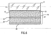
- FIG. 6 is a cross sectional view of a more preferred embodiment of an undercoated print, in which The printed layer (13) on the plastic base (11) together form a printed transparency (15).
- the under side of the printed transparency (15) is coated with a metallized thermally transferred protective undercoat (27) which begins with an adhesive layer (17) coated directly onto the printed layer (13).
- Under the adhesive layer (17) is a white matte layer (19) that is directly undercoated with a reflective metal layer (21) (the metal layer in a most preferred embodiment can be aluminum, but other metal coating materials such as silver, indium, zinc, chromium, nickel, gallium, cadmium, palladium, molybdenum and combinations thereof can also be used).
- the reflective layer metal (21) is undercoated with a protective layer (23). This protective layer is lastly undercoated with a release layer (25) that forms the separating layer between the metallized thermally transferred underlayer (27) and the ribbon carrier layer of the donor web (not shown).
Landscapes
- Thermal Transfer Or Thermal Recording In General (AREA)
- Accessory Devices And Overall Control Thereof (AREA)
- Ink Jet Recording Methods And Recording Media Thereof (AREA)
- Decoration By Transfer Pictures (AREA)
- Ink Jet (AREA)
- Duplication Or Marking (AREA)
Claims (10)
- Ein Verfahren zum Erhalten einer Schutzgrundierung (7; 116; 27) auf einer bedruckten Oberfläche eines transparenten Mediums (2; 12; 15), das folgende Schritte umfasst:Bereitstellen eines transparenten Mediums (2; 12; 15);Drucken zumindest eines gedruckten Bildes (4; 114; 13) auf die Unteroberfläche des transparenten Mediums;Bereitstellen einer Basis (22), die eine nichtklebende Oberfläche aufweist;Halten des transparenten Mediums durch die nichtklebende Oberfläche der Basis (22);Bereitstellen einer Spenderbahn, die eine Trägerseite (11) und eine Transferseite (17) aufweist, wobei die Trägerseite ein Trägerbandmaterial (3) aufweist und die Transferseite ein Schutzgrundierungsmaterial (7) aufweist;Abrollen der Spenderbahn von einer Quellenrolle (16) gegen die Verarbeitungsrichtung und von einer Aufnahmerolle (18) in Verarbeitungsrichtung;Spannen der Spenderbahn mittels der Quellenrolle (16) und der Aufnahmerolle (18);Bereitstellen eines Heiz-/Druckelements (14);gleichmäßiges Anlegen von Wärme und Druck an einen Abschnitt der Trägerseite (11) der Spenderbahn mittels des Heiz-/Druckelements (14), dadurch Anhaften eines Abschnitts des Schutzgrundierungsmaterials (7) auf der bedruckten Unteroberfläche des transparenten Mediums (2; 12; 15); undFreigeben des Abschnitts des an der Unteroberfläche des transparenten Mediums (2; 12; 15) anhaftenden Grundierungsmaterials (7) mittels eines Drehmoments von der Aufnahmerolle (18), die die Spenderbahn zieht;wobei sich die nichtklebende Oberfläche der Basis (22), die Spenderbahn und das Heiz-/Druckelement (14) über die Breite des transparenten Mediums (2; 12; 15) hinaus erstrecken, so dass der freigegebene Abschnitt durch die Ränder des transparenten Mediums (2; 12, 15) definiert ist und ohne ein Trimmen an den Rändern sauber von dem Trägerbandmaterial (3) getrennt ist.
- Das Verfahren gemäß Anspruch 1, bei dem das zumindest eine gedruckte Bild (4; 114; 13) mit wasserbasierter Tinte tintenstrahlgedruckt wird.
- Das Verfahren gemäß Anspruch 1, bei dem das zumindest eine gedruckte Bild (4; 114; 13) mit Tinte, die aus der Gruppe ausgewählt ist, die aus einer farbstoffbasierten Tinte und einer pigmentbasierten Tinte besteht, tintenstrahlgedruckt wird.
- Das Verfahren gemäß Anspruch 2 oder 3, bei dem überschüssige Feuchtigkeit von dem zumindest einen tintenstrahlgedruckten Bild (4; 114; 13) durch den Abschnitt des Grundierungsmaterials (7) abgeführt wird.
- Das Verfahren gemäß einem der Ansprüche 2 bis 4, bei dem vor dem Schritt des Aufbringens des Schutzgrundierungsmaterials (7) auf die tintenstrahlbedruckte Unteroberfläche des transparenten Mediums (2; 12; 15) ferner ein Schritt des Trocknens des zumindest einen tintenstrahltintengedruckten Bildes (4; 114; 13) auf der Unteroberfläche mit einer Trocknungsvorrichtung vorgesehen ist, die aus der Gruppe ausgewählt ist, die aus einer abstrahlenden Heizvorrichtung, einer leitfähigen Heizvorrichtung, einer konvektiven Blasvorrichtung, einer Infrarot-Vorrichtung, einem abstrahlenden Infrarot-Heizelement, einer Ultraviolett-Vorrichtung und einer Mikrowellenvorrichtung besteht.
- Eine Vorrichtung zum Erhalten einer Schutzgrundierung (7; 116; 27) auf einer bedruckten Oberfläche eines transparenten Mediums (2; 12; 15), die folgende Merkmale aufweist:eine Basis (22), die eine nichtklebende Oberfläche zum Tragen des transparenten Mediums (2; 12; 15) aufweist;eine Spenderbahn, die eine Trägerseite (11) und eine Transferseite (17) aufweist, wobei die Trägerseite ein Trägerbandmaterial (3) aufweist und die Transferseite ein Schutzgrundierungsmaterial (7) aufweist;eine Quellenrolle (16) und eine Aufnahmerolle (18), die zusammen eine Bandhabungsvorrichtung zum Abrollen und Spannen der Spenderbahn umfassen; undein Heiz-/Druckelement (14) zum gleichmäßigen Anlegen von Wärme und Druck an einen Abschnitt der Trägerseite (11) der Spenderbahn, um das Schutzgrundierungsmaterial (7) auf die bedruckte Unteroberfläche des transparenten Mediums (2; 12; 15) aufzubringen, wobei das Heiz-/Druckelement (14) entweder eine Oberfläche mit einer Größe und Gestalt, die zu der Oberfläche des transparenten Mediums (2; 12; 15) äquivalent sind, oder zumindest eine Wärmerolle umfasst, die an die gesamte Fläche der Oberfläche des transparenten Mediums (2; 12; 15) Wärme und Kraft anlegt;wobei im Gebrauch ein Drehmoment von der Aufnahmerolle (18) den Abschnitt des Grundierungsmaterials (7), der an der Unteroberfläche des transparenten Mediums (2; 12; 15) haftet, freigibt,wobei sich die nichtklebende Oberfläche der Basis (22), die Spenderbahn und das Heiz-/Druckelement (14) über die Breite des transparenten Mediums (2; 12; 15) hinaus erstrecken, so dass der freigegebene Abschnitt durch die Ränder des transparenten Mediums (2; 12, 15) definiert ist und ohne ein Trimmen an den Rändern sauber von dem Trägerbandmaterial (3) getrennt ist.
- Die Vorrichtung gemäß Anspruch 6, bei der das zumindest eine gedruckte Bild (4; 114; 13) mit wasserbasierter Tinte tintenstrahlgedruckt ist.
- Die Vorrichtung gemäß Anspruch 6, bei der das zumindest eine gedruckte Bild (4; 114; 13) mit Tinte, die aus der Gruppe ausgewählt ist, die aus einer farbstoffbasierten Tinte und einer pigmentbasierten Tinte besteht, tintenstrahlgedruckt ist.
- Die Vorrichtung gemäß Anspruch 7 oder 8, bei der der Abschnitt des Grundierungsmaterials (7) dahin gehend angepasst ist, überschüssige Feuchtigkeit aus dem zumindest einen tintenstrahlgedruckten Bild (4; 114; 13) durch denselben abzuführen.
- Die Vorrichtung gemäß einem der Ansprüche 7 bis 9, die ferner eine Trocknungsvorrichtung umfasst, die aus der Gruppe ausgewählt ist, die aus einer abstrahlenden Heizvorrichtung, einer leitfähigen Heizvorrichtung, einer konvektiven Blasvorrichtung, einer Infrarot-Vorrichtung, einem abstrahlenden Infrarot-Heizelement, einer Ultraviolett-Vorrichtung und einer Mikrowellenvorrichtung besteht, dahin gehend angepasst, das zumindest eine tintenstrahltintengedruckte Bild (4; 114; 13) auf der Unteroberfläche zu trocknen.
Applications Claiming Priority (2)
| Application Number | Priority Date | Filing Date | Title |
|---|---|---|---|
| US63031800A | 2000-07-31 | 2000-07-31 | |
| US630318 | 2000-07-31 |
Publications (3)
| Publication Number | Publication Date |
|---|---|
| EP1177912A2 EP1177912A2 (de) | 2002-02-06 |
| EP1177912A3 EP1177912A3 (de) | 2003-08-27 |
| EP1177912B1 true EP1177912B1 (de) | 2007-04-04 |
Family
ID=24526698
Family Applications (1)
| Application Number | Title | Priority Date | Filing Date |
|---|---|---|---|
| EP01306540A Expired - Lifetime EP1177912B1 (de) | 2000-07-31 | 2001-07-31 | Verfahren zum Herstellen eines mit einer Schutzunterbeschichtung bedruckten Mediums |
Country Status (5)
| Country | Link |
|---|---|
| US (1) | US6808583B2 (de) |
| EP (1) | EP1177912B1 (de) |
| JP (1) | JP2002120434A (de) |
| DE (1) | DE60127619T2 (de) |
| HK (1) | HK1040220B (de) |
Families Citing this family (14)
| Publication number | Priority date | Publication date | Assignee | Title |
|---|---|---|---|---|
| US20020101497A1 (en) * | 2001-01-30 | 2002-08-01 | Kwasny David M. | Method for creating durable printed CD's using clear hot stamp coating |
| US8252409B2 (en) | 2004-02-19 | 2012-08-28 | Hewlett-Packard Development Company, L.P. | Durable printed composite materials and associated methods |
| US8163075B2 (en) | 2006-10-31 | 2012-04-24 | Sensient Colors Llc | Inks comprising modified pigments and methods for making and using the same |
| WO2009026552A2 (en) | 2007-08-23 | 2009-02-26 | Sensient Colors Inc. | Self-dispersed pigments and methods for making and using the same |
| CN101557942B (zh) * | 2007-12-20 | 2012-07-04 | Lg化学株式会社 | 包括含有反光颗粒的氟树脂层的转移片材和包括含有反光颗粒的氟树脂层的外用层压片材及其制备方法 |
| JP4633808B2 (ja) * | 2008-01-31 | 2011-02-16 | 株式会社ミマキエンジニアリング | インクジェットプリンタ及び印刷方法 |
| US8240841B2 (en) * | 2009-01-03 | 2012-08-14 | David M Caracciolo | Pulse drying system |
| AU2010234392A1 (en) | 2009-04-07 | 2011-10-27 | Sensient Colors Inc. | Self-dispersing particles and methods for making and using the same |
| US8840745B2 (en) * | 2011-06-30 | 2014-09-23 | Paul Green | Method of printing foil images upon textiles |
| WO2013109788A1 (en) * | 2012-01-17 | 2013-07-25 | Perfect Fit Technologies, Inc. | Protective coverings, systems for installing protective coverings and methods of making the same |
| US9321280B2 (en) | 2012-10-24 | 2016-04-26 | Hewlett-Packard Development Company, L.P. | Spatial misalignment of a pre-treatment composition relative to an ink composition |
| CN103303017B (zh) * | 2013-05-09 | 2015-08-05 | 福州皇家地坪有限公司 | 地坪艺术彩印方法及设备 |
| US10639921B2 (en) | 2016-07-26 | 2020-05-05 | Hewlett-Packard Development Company, L.P. | Transfer printing |
| WO2021131496A1 (ja) * | 2019-12-25 | 2021-07-01 | 富士フイルム株式会社 | 画像記録方法 |
Family Cites Families (29)
| Publication number | Priority date | Publication date | Assignee | Title |
|---|---|---|---|---|
| US2370314A (en) * | 1942-01-24 | 1945-02-27 | Cities Service Oil Co | Rope lubricating apparatus |
| IT996938B (it) * | 1973-11-12 | 1975-12-10 | Acerbi Virgilio | Dispositivo ingrassatore per cavi |
| US4046225A (en) * | 1975-08-11 | 1977-09-06 | Bell Telephone Laboratories, Incorporated | Cable lubrication method |
| US4169427A (en) * | 1976-04-14 | 1979-10-02 | Crump Desmond G | Cable cleaning unit |
| US4336866A (en) * | 1980-01-24 | 1982-06-29 | Blanton Jr Kistler J | Wire rope lubricator cleaner |
| NO164671C (no) * | 1980-10-06 | 1995-04-03 | Steinar Johansen | Fremgangsmåte til smöring av ståltau. |
| US4498558A (en) * | 1982-03-02 | 1985-02-12 | Dynalube Holdings Limited | Cable lubricating device |
| JPS60189486A (ja) * | 1984-03-09 | 1985-09-26 | Ricoh Co Ltd | 画像の堅牢化方法 |
| US4749059A (en) * | 1986-01-17 | 1988-06-07 | American Polywater Corporation | Apparatus and method for lubricating cables |
| US4853706A (en) * | 1987-09-17 | 1989-08-01 | Brimer R Hugh Van | Transparency with jetted color ink and method of making same |
| US4862996A (en) * | 1988-06-06 | 1989-09-05 | Ron Chisholm | Apparatus for applying a liquid to a wire rope |
| JP3213969B2 (ja) * | 1990-07-27 | 2001-10-02 | キヤノン株式会社 | ラミネート装置及び画像形成装置 |
| US5107961A (en) * | 1991-03-26 | 1992-04-28 | Freedom Industries, Inc. | Fixture for a cable lubricating device |
| US5333704A (en) * | 1993-04-01 | 1994-08-02 | John Hoff | Rotating lubricating technique for equipment |
| US5555011A (en) * | 1994-01-26 | 1996-09-10 | Eastman Kodak Company | Lamination of a protective layer over an image produced by a thermal printer |
| US5441838A (en) * | 1994-04-18 | 1995-08-15 | Xerox Corporation | Simulated gloss process |
| WO1995030547A1 (en) * | 1994-05-09 | 1995-11-16 | Eastman Kodak Company | Recording process |
| US5942330A (en) * | 1994-05-19 | 1999-08-24 | Bostik, Incorporated | Adhesive compositions and methods and articles of manufacture comprising same |
| US5798161A (en) * | 1995-01-20 | 1998-08-25 | Dai Nippon Printing Co., Ltd. | Optical disk, method of forming image on optical disk, image forming apparatus and adhesive layer transfer sheet |
| JPH09226107A (ja) * | 1996-02-26 | 1997-09-02 | Seiko Epson Corp | 印刷シートの製造方法及びそれに用いるインクジェットプリンタ |
| JP3744117B2 (ja) * | 1997-04-28 | 2006-02-08 | 凸版印刷株式会社 | 転写方式によるオーバーコーティング装置 |
| US6264296B1 (en) * | 1997-05-06 | 2001-07-24 | Fargo Electronics, Inc. | Ink jet identification card printer with lamination station |
| JP3571186B2 (ja) * | 1997-06-23 | 2004-09-29 | ニスカ株式会社 | 情報カード形成装置および情報カード形成装置を内臓もしくは接続可能にしたプリンタ |
| US6095220A (en) * | 1997-06-23 | 2000-08-01 | Nisca Corporation | Overcoat fixing device |
| JPH1134310A (ja) * | 1997-07-23 | 1999-02-09 | Canon Inc | インクジェット記録方法及び装置 |
| JP3905628B2 (ja) * | 1997-10-22 | 2007-04-18 | 富士フイルム株式会社 | フィルム張付制御方法 |
| JPH11157165A (ja) * | 1997-11-28 | 1999-06-15 | Copal Co Ltd | 保護膜形成装置 |
| JP3629135B2 (ja) * | 1998-02-25 | 2005-03-16 | 株式会社東芝 | 保護膜転写装置及びカード作成装置 |
| US6454896B1 (en) * | 2000-02-04 | 2002-09-24 | Eastman Kodak Company | Process for laminating an ink jet print |
-
2001
- 2001-07-31 EP EP01306540A patent/EP1177912B1/de not_active Expired - Lifetime
- 2001-07-31 JP JP2001231420A patent/JP2002120434A/ja active Pending
- 2001-07-31 DE DE60127619T patent/DE60127619T2/de not_active Expired - Lifetime
-
2002
- 2002-03-16 HK HK02102040.4A patent/HK1040220B/en not_active IP Right Cessation
-
2003
- 2003-05-16 US US10/439,798 patent/US6808583B2/en not_active Expired - Fee Related
Also Published As
| Publication number | Publication date |
|---|---|
| US6808583B2 (en) | 2004-10-26 |
| DE60127619D1 (de) | 2007-05-16 |
| US20030194524A1 (en) | 2003-10-16 |
| JP2002120434A (ja) | 2002-04-23 |
| DE60127619T2 (de) | 2007-11-22 |
| EP1177912A3 (de) | 2003-08-27 |
| EP1177912A2 (de) | 2002-02-06 |
| HK1040220B (en) | 2007-07-06 |
| HK1040220A1 (en) | 2002-05-31 |
Similar Documents
| Publication | Publication Date | Title |
|---|---|---|
| US7037398B2 (en) | Clear protective overcoat for a printed medium | |
| EP1177912B1 (de) | Verfahren zum Herstellen eines mit einer Schutzunterbeschichtung bedruckten Mediums | |
| EP1386752B1 (de) | Thermisches Schutzschichtübertragungsblatt und mattierter Abdruck | |
| EP1179753B1 (de) | Bildaufzeichungsverfahren | |
| US6654040B2 (en) | Method for creating durable electrophotographically printed color transparencies using clear hot stamp coating | |
| EP1229529A2 (de) | Verfahren zur Erzeugung von dauerhaften bedruckten CDs mit einer klaren Heissprägebeschichtung | |
| US6733844B2 (en) | Photographic-quality prints and methods for making the same | |
| JP2004001446A (ja) | 画像保護シート、画像保護液、インクジェット記録物とその製造方法 | |
| EP1566282B1 (de) | Beständige bedruckte Verbundmaterialien und damit zusammenhängende Verfahren | |
| US7770801B1 (en) | Environmentally favorable reward cards | |
| EP1101627A3 (de) | Aufzeichnungsmedium und Aufzeichnungsverfahren | |
| JP2004174965A (ja) | ラミネートフィルムおよびラミネート印画物 | |
| JP2003320622A (ja) | 熱転写型画像保護シート、保護層形成方法、ならびにその方法によって得られる記録物 | |
| JP6642187B2 (ja) | 被転写シートへの保護層または転写層の転写方法 | |
| US20040109953A1 (en) | Photographic-quality prints and methods for making the same | |
| JP2002254793A (ja) | 保護層転写フィルム、保護層転写方法及びそれによって得られる記録物 | |
| JP2003276176A (ja) | インクジェット記録装置、オーバーコート装置及びインクジェット記録物の製造方法 | |
| JP2004223968A (ja) | 画像保護方法、転写装置及び画像記録装置 | |
| JP2003103910A (ja) | 被記録媒体の保護体 | |
| JPH07242072A (ja) | 熱転写記録方法及び装置 | |
| JP2017065095A (ja) | 被転写体の表面処理方法及び印画物の製造方法 | |
| JPH02253989A (ja) | 感熱転写記録用受像紙 |
Legal Events
| Date | Code | Title | Description |
|---|---|---|---|
| PUAI | Public reference made under article 153(3) epc to a published international application that has entered the european phase |
Free format text: ORIGINAL CODE: 0009012 |
|
| AK | Designated contracting states |
Kind code of ref document: A2 Designated state(s): AT BE CH CY DE DK ES FI FR GB GR IE IT LI LU MC NL PT SE TR |
|
| AX | Request for extension of the european patent |
Free format text: AL;LT;LV;MK;RO;SI |
|
| PUAL | Search report despatched |
Free format text: ORIGINAL CODE: 0009013 |
|
| AK | Designated contracting states |
Designated state(s): AT BE CH CY DE DK ES FI FR GB GR IE IT LI LU MC NL PT SE TR |
|
| AX | Request for extension of the european patent |
Extension state: AL LT LV MK RO SI |
|
| 17P | Request for examination filed |
Effective date: 20031006 |
|
| 17Q | First examination report despatched |
Effective date: 20040112 |
|
| AKX | Designation fees paid |
Designated state(s): DE FR GB NL |
|
| GRAP | Despatch of communication of intention to grant a patent |
Free format text: ORIGINAL CODE: EPIDOSNIGR1 |
|
| GRAS | Grant fee paid |
Free format text: ORIGINAL CODE: EPIDOSNIGR3 |
|
| GRAA | (expected) grant |
Free format text: ORIGINAL CODE: 0009210 |
|
| AK | Designated contracting states |
Kind code of ref document: B1 Designated state(s): DE FR GB NL |
|
| REG | Reference to a national code |
Ref country code: GB Ref legal event code: FG4D |
|
| REF | Corresponds to: |
Ref document number: 60127619 Country of ref document: DE Date of ref document: 20070516 Kind code of ref document: P |
|
| REG | Reference to a national code |
Ref country code: HK Ref legal event code: GR Ref document number: 1040220 Country of ref document: HK |
|
| ET | Fr: translation filed | ||
| PLBE | No opposition filed within time limit |
Free format text: ORIGINAL CODE: 0009261 |
|
| STAA | Information on the status of an ep patent application or granted ep patent |
Free format text: STATUS: NO OPPOSITION FILED WITHIN TIME LIMIT |
|
| 26N | No opposition filed |
Effective date: 20080107 |
|
| REG | Reference to a national code |
Ref country code: GB Ref legal event code: 732E Free format text: REGISTERED BETWEEN 20120329 AND 20120404 |
|
| REG | Reference to a national code |
Ref country code: NL Ref legal event code: SD Effective date: 20120731 |
|
| PGFP | Annual fee paid to national office [announced via postgrant information from national office to epo] |
Ref country code: GB Payment date: 20130626 Year of fee payment: 13 |
|
| PGFP | Annual fee paid to national office [announced via postgrant information from national office to epo] |
Ref country code: NL Payment date: 20130624 Year of fee payment: 13 Ref country code: DE Payment date: 20130621 Year of fee payment: 13 |
|
| PGFP | Annual fee paid to national office [announced via postgrant information from national office to epo] |
Ref country code: FR Payment date: 20130722 Year of fee payment: 13 |
|
| REG | Reference to a national code |
Ref country code: DE Ref legal event code: R119 Ref document number: 60127619 Country of ref document: DE |
|
| REG | Reference to a national code |
Ref country code: NL Ref legal event code: V1 Effective date: 20150201 |
|
| GBPC | Gb: european patent ceased through non-payment of renewal fee |
Effective date: 20140731 |
|
| PG25 | Lapsed in a contracting state [announced via postgrant information from national office to epo] |
Ref country code: NL Free format text: LAPSE BECAUSE OF NON-PAYMENT OF DUE FEES Effective date: 20150201 |
|
| REG | Reference to a national code |
Ref country code: FR Ref legal event code: ST Effective date: 20150331 |
|
| PG25 | Lapsed in a contracting state [announced via postgrant information from national office to epo] |
Ref country code: DE Free format text: LAPSE BECAUSE OF NON-PAYMENT OF DUE FEES Effective date: 20150203 |
|
| REG | Reference to a national code |
Ref country code: DE Ref legal event code: R119 Ref document number: 60127619 Country of ref document: DE Effective date: 20150203 |
|
| PG25 | Lapsed in a contracting state [announced via postgrant information from national office to epo] |
Ref country code: GB Free format text: LAPSE BECAUSE OF NON-PAYMENT OF DUE FEES Effective date: 20140731 Ref country code: FR Free format text: LAPSE BECAUSE OF NON-PAYMENT OF DUE FEES Effective date: 20140731 |