EP1177871A2 - Verfahren und Vorrichtung zum Herstellen von mit Langfasern verstärkten Kunststoff-Formteilen - Google Patents
Verfahren und Vorrichtung zum Herstellen von mit Langfasern verstärkten Kunststoff-Formteilen Download PDFInfo
- Publication number
- EP1177871A2 EP1177871A2 EP01116789A EP01116789A EP1177871A2 EP 1177871 A2 EP1177871 A2 EP 1177871A2 EP 01116789 A EP01116789 A EP 01116789A EP 01116789 A EP01116789 A EP 01116789A EP 1177871 A2 EP1177871 A2 EP 1177871A2
- Authority
- EP
- European Patent Office
- Prior art keywords
- guide
- continuous thread
- roving
- thread
- piping system
- Prior art date
- Legal status (The legal status is an assumption and is not a legal conclusion. Google has not performed a legal analysis and makes no representation as to the accuracy of the status listed.)
- Granted
Links
Images

Classifications
-
- B—PERFORMING OPERATIONS; TRANSPORTING
- B29—WORKING OF PLASTICS; WORKING OF SUBSTANCES IN A PLASTIC STATE IN GENERAL
- B29C—SHAPING OR JOINING OF PLASTICS; SHAPING OF MATERIAL IN A PLASTIC STATE, NOT OTHERWISE PROVIDED FOR; AFTER-TREATMENT OF THE SHAPED PRODUCTS, e.g. REPAIRING
- B29C70/00—Shaping composites, i.e. plastics material comprising reinforcements, fillers or preformed parts, e.g. inserts
- B29C70/04—Shaping composites, i.e. plastics material comprising reinforcements, fillers or preformed parts, e.g. inserts comprising reinforcements only, e.g. self-reinforcing plastics
- B29C70/06—Fibrous reinforcements only
- B29C70/10—Fibrous reinforcements only characterised by the structure of fibrous reinforcements, e.g. hollow fibres
- B29C70/16—Fibrous reinforcements only characterised by the structure of fibrous reinforcements, e.g. hollow fibres using fibres of substantial or continuous length
-
- B—PERFORMING OPERATIONS; TRANSPORTING
- B29—WORKING OF PLASTICS; WORKING OF SUBSTANCES IN A PLASTIC STATE IN GENERAL
- B29C—SHAPING OR JOINING OF PLASTICS; SHAPING OF MATERIAL IN A PLASTIC STATE, NOT OTHERWISE PROVIDED FOR; AFTER-TREATMENT OF THE SHAPED PRODUCTS, e.g. REPAIRING
- B29C70/00—Shaping composites, i.e. plastics material comprising reinforcements, fillers or preformed parts, e.g. inserts
- B29C70/04—Shaping composites, i.e. plastics material comprising reinforcements, fillers or preformed parts, e.g. inserts comprising reinforcements only, e.g. self-reinforcing plastics
- B29C70/28—Shaping operations therefor
- B29C70/30—Shaping by lay-up, i.e. applying fibres, tape or broadsheet on a mould, former or core; Shaping by spray-up, i.e. spraying of fibres on a mould, former or core
- B29C70/305—Spray-up of reinforcing fibres with or without matrix to form a non-coherent mat in or on a mould
-
- B—PERFORMING OPERATIONS; TRANSPORTING
- B65—CONVEYING; PACKING; STORING; HANDLING THIN OR FILAMENTARY MATERIAL
- B65H—HANDLING THIN OR FILAMENTARY MATERIAL, e.g. SHEETS, WEBS, CABLES
- B65H51/00—Forwarding filamentary material
- B65H51/16—Devices for entraining material by flow of liquids or gases, e.g. air-blast devices
-
- B—PERFORMING OPERATIONS; TRANSPORTING
- B65—CONVEYING; PACKING; STORING; HANDLING THIN OR FILAMENTARY MATERIAL
- B65H—HANDLING THIN OR FILAMENTARY MATERIAL, e.g. SHEETS, WEBS, CABLES
- B65H59/00—Adjusting or controlling tension in filamentary material, e.g. for preventing snarling; Applications of tension indicators
- B65H59/10—Adjusting or controlling tension in filamentary material, e.g. for preventing snarling; Applications of tension indicators by devices acting on running material and not associated with supply or take-up devices
- B65H59/105—Adjusting or controlling tension in filamentary material, e.g. for preventing snarling; Applications of tension indicators by devices acting on running material and not associated with supply or take-up devices the material being subjected to the action of a fluid
-
- B—PERFORMING OPERATIONS; TRANSPORTING
- B29—WORKING OF PLASTICS; WORKING OF SUBSTANCES IN A PLASTIC STATE IN GENERAL
- B29C—SHAPING OR JOINING OF PLASTICS; SHAPING OF MATERIAL IN A PLASTIC STATE, NOT OTHERWISE PROVIDED FOR; AFTER-TREATMENT OF THE SHAPED PRODUCTS, e.g. REPAIRING
- B29C67/00—Shaping techniques not covered by groups B29C39/00 - B29C65/00, B29C70/00 or B29C73/00
- B29C67/24—Shaping techniques not covered by groups B29C39/00 - B29C65/00, B29C70/00 or B29C73/00 characterised by the choice of material
- B29C67/246—Moulding high reactive monomers or prepolymers, e.g. by reaction injection moulding [RIM], liquid injection moulding [LIM]
-
- B—PERFORMING OPERATIONS; TRANSPORTING
- B65—CONVEYING; PACKING; STORING; HANDLING THIN OR FILAMENTARY MATERIAL
- B65H—HANDLING THIN OR FILAMENTARY MATERIAL, e.g. SHEETS, WEBS, CABLES
- B65H2701/00—Handled material; Storage means
- B65H2701/30—Handled filamentary material
- B65H2701/31—Textiles threads or artificial strands of filaments
Definitions
- the invention relates to a method and an apparatus for producing Long fibers reinforced plastic molded parts, with an endless thread or roving withdrawn from a coil, conveyed via a piping system to a cutting unit, here cut into finite sections forming long fibers, these long fibers a flowable, solid plastic via a conveyor channel Electricity is supplied and combined with it, this current in a mold entered, this closed and after curing the finished molded part is removed from the mold.
- Long fibers are understood to be those which are continuous threads or rovings, in particular fiberglass rovings, fed and shortly before the introduction into the Plastic melt or in the flowable reaction mixture to a finite Length of preferably more than 10 mm can be cut (DE 196 18 393 A1, WO 98/01274, WO 96/35562).
- the ends of the filaments wound on coils or rovings are joined together with splicing, so when pulling off no interruption takes place.
- the continuous thread or roving is fed partly from the storage location of the coils through the free space or through a piping system. There is at least one point in this piping system a conveyor air supply arranged. With this conveying air the Continuous thread pneumatically conveyed to the cutting unit. Even the cut ones Continuous threads are usually conveyed pneumatically to get them out into the stream enter liquid plastic.
- This method shows two problems in particular: First, when distributing of the batch in the mold cavity once by the movement of the entry device more and less needed for long fibers. Accordingly also fluctuates the need for the fed continuous thread or roving. Second is through the discontinuous mode of operation not only feeding or conveying the long fibers, but also the continuous thread or roving from mold filling to mold filling interrupted. As a result, the continuous thread is often not slowed down so quickly as desired and loops are formed. To avoid such is the use known from tensioners. When introducing long fibers into liquid Plastic melting with a solidification time that is not too short is a withdrawal speed of the continuous thread from 0.5 to approx. 2 m / s is usual, which makes the process usually just runs without too much problems. Disorders such as by tearing the continuous thread, but cannot be excluded.
- the object is to create a method and a device with which in the production of molded plastic parts reinforced with long fibers trouble-free feeding of the continuous thread or roving, especially with higher ones Take-off speeds ensured.
- the new process solves this problem by the fact that the continuous thread or roving in the piping system against the direction of delivery, pneumatically below Tension is held.
- This new procedure improves the production of reinforced with long fibers Molded parts already at the known low withdrawal speeds of the continuous thread essential. At higher take-off speeds, it is for one smooth operation is essential.
- the continuous thread promoted in the first part of the guide in a rigid piping system and in a second part of the guide in one with a controlled entry device moving pipe system continued, the continuous thread in this pipe system only by funding in the direction of a arranged on the entry device Conveyor is tensioned.
- the stream forming a solid plastic is preferably in the form of a short reaction start time having liquid reaction mixture supplied.
- the continuous filaments are used in the usual plastic melts generally fed at a take-off speed of 0.5 to approx. 2.0 m / s.
- the continuous filaments with a Speed of at least 2.0 m / s fed In an advantageous manner, the continuous filaments with a Speed of at least 2.0 m / s fed.
- the new device for the production of molded plastic parts reinforced with long fibers in a mold starts from a storage location for coils Continuous threads or rovings, of which a guide for the continuous thread from the Storage point up to a motion-controlled entry device for one leads solid plastic-forming liquid stream and on a cutter Conveyor ends, with the guide for the continuous thread or roving at least partly consists of a rigid piping system.
- the rigid piping system is at least one of the Direction of delivery opposite air inlet for pneumatic clamping of the Continuous thread or rovings.
- the spatial guidance for the continuous thread or roving can also partially consist of eyelets through which it is freely guided through the room, so to speak.
- a piping system is essential so that the airflow to the pneumatic clamping is positively guided. This only makes it possible for the Continuous thread or roving always, i.e. even during breaks between two Mold filling processes, remains tense or at the beginning of the next mold filling process is under pneumatic tension. If the funding towards the end of the form filling is interrupted, the conveyor comes to a standstill with a delay. Because during this time, the conveying of the continuous thread or roving is still running, loops could form in the piping system. But these are through the Avoid tensioning.
- the guidance exists of the continuous thread or roving on the motion-controlled entry device from a flexible guide hose which connects to the rigid piping system followed.
- This embodiment allows the guide tube to move adapts the entry device.
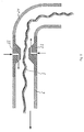
- the part arranged on the entry device is the guide is separated from the rest of the rigid piping system and points to it Entrance to a funnel in which the continuous thread during the form filling process enters.
- the part of the guide arranged on the entry device is either as rigid guide tube or designed as a flexible guide hose.
- the funnel has such a diameter that it is also in an extreme position or - Movement of the entry device the incoming filament or roving fields.
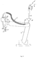
- the guide on the entry device consists of a flexible guide hose, this is preferably connected to the rigid piping system and has a length that compensates for the movements of the entry device.
- the guide preferably has at least one conveying air inlet.
- the end of the rigid pipe system preferably has a telescopic pipe, which can be extended to the subsequent hopper during setup.
- This embodiment is in connection with a conveying air inlet when threading of the piping system particularly advantageous so that the continuous thread or Roving is conveyed to the cutting unit without difficulty until it is there arranged conveyor detected.
- a conveying air inlet when threading of the piping system particularly advantageous so that the continuous thread or Roving is conveyed to the cutting unit without difficulty until it is there arranged conveyor detected.
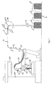
- the device consists of a bearing 1 for several coils 2 from continuous filaments 3 in the form of glass fiber rovings.
- An endless thread 3 passes over a funnel 4 in a guide 5, the first part of a rigid piping system 6, which through the free space to a controlled and movable laterally pivotable entry device 7 leads.
- a telescopic tube 9 is arranged, which is in set-up mode can be lowered down to a funnel 10.
- the funnel 10 has such a diameter that the incoming endless thread 3 even with extreme movements of the entry device 7 is always caught.
- This funnel 10 is then the Guide 5 is designed as a flexible guide hose 11 and leads to a Cutting device 12, which is provided with a conveyor device 13.
- the entry device 7 is with a mixing head 14 for the reaction components forming a foam Polyol and isocyanate.
- the well known Feeds of these reaction components are not shown.
- the mixing head 14 has an outlet opening 15, which in the lower mold half 16 of an open Molding tool points.
- the upper mold half 17 is on a guide shaft 18 held lowerable.
- From the cutting unit 12 leads a guide tube 19 for the Continuous thread 3 cut long fibers 20 in the direction of from the outlet opening 15 emerging stream 21 of the reaction mixture.
- Both the rigid The piping system 6 and the flexible guide hose 11 have conveying air inlets 22, which point in the conveying direction.
- the rigid piping system 6 is also provided with air inlets 23.
- the device according to FIGS. 1 to 3 is selected.
- the continuous thread 3 is switched on by hand when the conveying air supply is switched on the funnel 4 inserted, captured by the air flow and conveyed until it is from the conveyor 13 is detected on the cutting unit 12.
- the pneumatic conveying air switched off and switched to the mold filling process. That is, in the mixing head 14, a reaction mixture is produced in a continuous process in the so-called shot process Polyol and isocyanate produced for a mold filling. This has a reaction start time of about 15 seconds. Within this time, the cutting unit 12 cut long fibers 20 of 15 mm in length in the mixture flow in the desired amount of 25 percent by mass can be introduced into the finished molded part.
- the continuous thread 3 is fed at a take-off speed of 4.0 m / s.
- An air flow acts on the conveying process for permanent tensioning of the Continuous thread 3 with a force of 1.5 N.
- the entry device 7 is program-controlled in their movement, so that the entry in the lower Mold half 16 is carried out homogeneously. If the lower mold half 16 is filled, both the mixing head 14 and the conveyor 13 are switched off. In doing so, a Tracking of the continuous thread 3, which could form undesirable loops, avoided by stretching it.
- the entry device 7 is pivoted out laterally and the upper mold half 17 lowered onto the lower mold half 16 put on and both locked together. After curing, this is done with long fibers 20 reinforced molded part demolded.
Landscapes
- Engineering & Computer Science (AREA)
- Chemical & Material Sciences (AREA)
- Composite Materials (AREA)
- Mechanical Engineering (AREA)
- Textile Engineering (AREA)
- Moulding By Coating Moulds (AREA)
- Reinforced Plastic Materials (AREA)
- Casting Or Compression Moulding Of Plastics Or The Like (AREA)
Abstract
Description
Claims (11)
- Verfahren zum Herstellen von mit Langfasern (20) verstärkten Kunststoff-Formteilen, wobei ein Endlosfaden (3) bzw. Roving von einem Coil (2) abgezogen, über eine Führung (5) zu einem Schneidwerk (12) gefördert, hier in endliche, Langfasern (20) bildende Abschnitte geschnitten, diese Langfasern (20) über ein Führungsrohr (19) einem fließfähigen, einen festen Kunststoff bildenden Strom (21) zugeführt und mit ihm vereinigt werden, wobei dieser Strom (21) in ein Formwerkzeug (16, 17) eingetragen, dieses verschlossen und nach dem Aushärten das fertige Formteil entformt wird, dadurch gekennzeichnet, dass der Endlosfaden (3) bzw. Roving in der Führung (5) entgegen der Förderrichtung ständig pneumatisch unter Spannung gehalten wird.
- Verfahren nach Anspruch 1, dadurch gekennzeichnet, dass der Endlosfaden (3) im ersten Teil der Führung (5) in einem starren Rohrleitungssystem (6) gefördert wird und im zweiten Teil der Führung (5) in einem mit einer gesteuerten Eintragsvorrichtung (7, 34) bewegten Leitungssystem (11) weitergeführt wird, wobei der Endlosfaden (3) in diesem Leitungssystem (11) nur durch Förderung in Richtung einer an der Eintragsvorrichtung (7, 34) angeordneten Fördervorrichtung (13) gespannt wird.
- Verfahren nach den Ansprüchen 1 oder 2, dadurch gekennzeichnet, dass der einen festen Kunststoff bildende Strom (21) in Form eines eine kurze Reaktionsstartzeit aufweisenden flüssigen Reaktionsgemisches zugeführt wird.
- Verfahren nach den Ansprüchen 1, 2 oder 3, dadurch gekennzeichnet, dass der Endlosfaden (3) mit einer Abzugsgeschwindigkeit von mindestens 2,0 m/s abgezogen wird.
- Vorrichtung zum Herstellen von mit Langfasern (20) verstärkten Kunststoff-Fomiteilen in einem Formwerkzeug, bestehend aus einer Lagerstelle (1) für Coils (2) aus Endlosfäden (3) oder Rovings, von welcher eine Führung (5) für den Endlosfaden (3) von der Lagerstelle (1) bis zu einer bewegungsgesteuerten Eintragsvorrichtung (7, 34) für einen einen festen Kunststoff bildenden flüssigen Strom (21) führt und an einem Schneidwerk (12) mit Fördervorrichtung (13) endet, wobei die Führung (5) für den Endlosfaden (3) oder Roving mindestens teilweise aus einem starren Rohrleitungssystem (6) besteht, dadurch gekennzeichnet, dass das starre Rohrleitungssystem (6) mindestens einen der Förderrichtung entgegengerichteten Spannlufteinlass (23) zum pneumatischen Spannen des Endlosfadens (3) oder Rovings aufweist.
- Vorrichtung nach Anspruch 5, dadurch gekennzeichnet, dass die Führung (5) des Endlosfadens (3) oder Rovings an der bewegungsgesteuerten Eintragsvorrichtung (7) aus einem biegsamen Führungsschlauch (11) besteht, welcher an das starre Rohrleitungssystem (6) anschließt.
- Vorrichtung nach Anspruch 5, dadurch gekennzeichnet, dass der an der Eintragsvorrichtung (7) angeordnete Teil der Führung (5) vom starren Rohrleitungssystem (6) getrennt ist und dass sein Eingang einen Trichter (10) aufweist, in welchen der Endlosfaden (3) während des Formfüllvorganges einläuft.
- Vorrichtung nach Anspruch 6, dadurch gekennzeichnet, dass der biegsame Führungsschlauch (31) mit dem starren Rohrleitungssystem (32) verbunden ist und eine Länge aufweist, welche die Bewegungen der Eintragsvorrichtung (34) ausgleicht.
- Vorrichtung nach den Ansprüchen 5 bis 8, wobei das starre Rohrleitungssystem (5) Rohrbögen (24) aufweist, dadurch gekennzeichnet, dass zumindest hinter einem der Rohrbögen (24) ein weiterer Spannlufteinlass (23) zum Spannen des Endlosfadens (3) oder Rovings angeordnet ist.
- Vorrichtung nach den Ansprüchen 5 bis 7 oder 9, dadurch gekennzeichnet, dass die Führung (5) mindestens einen Förderlufteinlass (22) aufweist.
- Vorrichtung nach den Ansprüchen 7 und 10, dadurch gekennzeichnet, dass das Ende des starren Rohrleitungssystems (6) ein Teleskoprohr (9) aufweist, welches bei Rüstbetrieb bis auf den nachfolgenden Trichter (10) ausfahrbar ist.
Applications Claiming Priority (2)
| Application Number | Priority Date | Filing Date | Title |
|---|---|---|---|
| DE10037773A DE10037773C1 (de) | 2000-08-03 | 2000-08-03 | Verfahren und Vorrichtung zum Herstellen von mit Langfasern verstärkten Kunststoff-Formteilen |
| DE10037773 | 2000-08-03 |
Publications (3)
| Publication Number | Publication Date |
|---|---|
| EP1177871A2 true EP1177871A2 (de) | 2002-02-06 |
| EP1177871A3 EP1177871A3 (de) | 2003-08-13 |
| EP1177871B1 EP1177871B1 (de) | 2007-04-25 |
Family
ID=7651144
Family Applications (1)
| Application Number | Title | Priority Date | Filing Date |
|---|---|---|---|
| EP01116789A Expired - Lifetime EP1177871B1 (de) | 2000-08-03 | 2001-07-23 | Verfahren und Vorrichtung zum Herstellen von mit Langfasern verstärkten Kunststoff-Formteilen |
Country Status (7)
| Country | Link |
|---|---|
| US (1) | US6808378B2 (de) |
| EP (1) | EP1177871B1 (de) |
| JP (1) | JP2002059446A (de) |
| KR (1) | KR20020011900A (de) |
| CN (1) | CN1346737A (de) |
| AT (1) | ATE360520T1 (de) |
| DE (2) | DE10037773C1 (de) |
Cited By (15)
| Publication number | Priority date | Publication date | Assignee | Title |
|---|---|---|---|---|
| FR2912953A1 (fr) * | 2007-02-28 | 2008-08-29 | Coriolis Composites Sa | Machine d'application de fibres avec tubes flexibles d'acheminement de fibres |
| FR2937582A1 (fr) * | 2008-10-28 | 2010-04-30 | Coriolis Composites | Machine d'application de fibres avec tubes flexibles d'acheminement de fibres places dans une gaine froide |
| US7926537B2 (en) | 2007-03-06 | 2011-04-19 | Coriolis Composites | Applicator head for fibers with particular systems for cutting fibers |
| US8052819B2 (en) | 2009-04-02 | 2011-11-08 | Coriolis Composites | Method and machine for applying a band of fibers on convex surfaces and/or with edges |
| US8057618B2 (en) | 2007-02-21 | 2011-11-15 | Coriolis Composites | Method and apparatus for making structures of composite material, in particular airplane fuselage sections |
| US8191596B2 (en) | 2009-07-17 | 2012-06-05 | Coriolis Composites | Fiber application machine comprising a flexible compacting roller with a thermal regulation system |
| RU2494953C1 (ru) * | 2012-04-24 | 2013-10-10 | Федеральное государственное бюджетное образовательное учреждение высшего профессионального образования "Московский государственный технологический университет "СТАНКИН" (ФГБОУ ВПО МГТУ "СТАНКИН") | Способ подачи армирующих волокон для технологических линий непрерывного изготовления изделий из полимерных композиционных материалов |
| US8733417B2 (en) | 2005-03-03 | 2014-05-27 | Coriolis Composites | Fiber application machine |
| FR3009827A1 (de) * | 2013-08-23 | 2015-02-27 | Deutsch Zentr Luft & Raumfahrt | |
| US10369594B2 (en) | 2015-04-01 | 2019-08-06 | Coriolis Group | Fiber application head with a specific application roll |
| US10821682B2 (en) | 2015-10-28 | 2020-11-03 | Coriolis Group | Fiber application machine comprising specific cutting systems |
| US10894341B2 (en) | 2016-03-07 | 2021-01-19 | Coriolis Group | Method for producing preforms with application of a binder to dry fiber, and corresponding machine |
| WO2021232079A1 (de) | 2020-05-18 | 2021-11-25 | Thomas Rettenwander | Verfahren zur herstellung eines faserkunststoffverbunds |
| US11491741B2 (en) | 2016-09-27 | 2022-11-08 | Coriolis Group | Process for producing composite material parts by impregnating a specific preform |
| US12343944B2 (en) | 2017-09-04 | 2025-07-01 | Coriolis Group | Method for producing a composite material part by oriented needling of a preform |
Families Citing this family (20)
| Publication number | Priority date | Publication date | Assignee | Title |
|---|---|---|---|---|
| US9408405B2 (en) * | 2003-10-03 | 2016-08-09 | Veijlen N.V. | Use of compounds that are able to increase the serum IGF-1 level for the preparation of a therapeutical composition for treatment of various disease states associated with a reduced IGF-1 serum level in humans and animals |
| JP4797661B2 (ja) * | 2006-02-02 | 2011-10-19 | マツダ株式会社 | 繊維強化樹脂成形品の成形方法および成形装置 |
| US7566165B2 (en) * | 2006-04-17 | 2009-07-28 | Milliken & Company | Valved manifold and system suitable for introducing one or more additives into a fluid stream |
| DE102007008390A1 (de) * | 2007-02-21 | 2008-08-28 | J.H. Ziegler Gmbh & Co. Kg | Verfahren und Vorrichtung zur Herstellung mindestens eines dreidimensional ausgeprägten Formteils |
| FR2913366B1 (fr) * | 2007-03-06 | 2009-05-01 | Coriolis Composites Sa | Tete d'application de fibres avec systemes de coupe et de blocage de fibres particuliers |
| DE102007051129A1 (de) * | 2007-10-24 | 2009-04-30 | Bayer Materialscience Ag | Vorrichtung und Verfahren zur Herstellung von verstärkten Polyurethan-Verbundmaterialen |
| CN101462358B (zh) * | 2007-12-19 | 2013-09-11 | 维斯塔斯风力系统有限公司 | 一种制备预成型件的设备 |
| DE102008017573A1 (de) * | 2008-04-07 | 2010-04-15 | Airbus Deutschland Gmbh | Verfahren zur Herstellung eines FVW/FVK-Bauteils aus Rovings mit einem Formwerkzeug und Formwerkzeug zur Durchführung des Verfahrens |
| JP5451007B2 (ja) * | 2008-08-26 | 2014-03-26 | 不双産業株式会社 | 製袋充填装置 |
| FR2948059B1 (fr) * | 2009-07-17 | 2011-08-05 | Coriolis Composites | Machine d'application de fibres avec rouleau de compactage transparent au rayonnement du systeme de chauffage |
| FR2972672B1 (fr) * | 2011-03-18 | 2013-03-15 | Coriolis Composites Attn Olivier Bouroullec | Machine d'application de fibres avec systeme de securite |
| FR2975334B1 (fr) | 2011-05-20 | 2016-04-15 | Coriolis Composites Attn Olivier Bouroullec | Tete d'application de fibres avec rouleau de compactage segmente |
| FR2975335B1 (fr) * | 2011-05-20 | 2013-05-17 | Coriolis Composites Attn Olivier Bouroullec | Machine d'application de fibres avec tubes flexibles d'acheminement de fibres munis de lames flexibles |
| EP2908038B1 (de) * | 2014-02-13 | 2020-04-01 | Airbus Operations GmbH | Verfahren und Robotersystem zur Befestigung einer Anordnung |
| DE102015121428B4 (de) * | 2015-12-09 | 2019-10-31 | Deutsches Zentrum für Luft- und Raumfahrt e.V. | Faserlegekopf und Faserlegeanlage sowie Verfahren zur Herstellung eines Faserverbundbauteils |
| CN105459413B (zh) * | 2015-12-29 | 2017-11-21 | 清华大学 | Frp箍筋的制造方法 |
| FR3072046B1 (fr) * | 2017-10-11 | 2019-10-25 | Fives Machining | Machine d'application d'au moins une fibre et procede associe |
| CN108275509A (zh) * | 2018-02-09 | 2018-07-13 | 廖罗明 | 一种扁丝送丝机及其控制方法 |
| US11331834B2 (en) | 2018-05-21 | 2022-05-17 | Arkal Automotive C.S. Ltd. | Injection moulding system and method |
| JP2026503196A (ja) * | 2022-11-01 | 2026-01-28 | ウェスタン ニュー イングランド ユニバーシティ | 制御された張力で任意の細いワイヤを送給する装置および方法 |
Family Cites Families (14)
| Publication number | Priority date | Publication date | Assignee | Title |
|---|---|---|---|---|
| AT308022B (de) * | 1969-06-21 | 1973-06-25 | Luigi Castelli | Fadenfördereinrichtung für Texilmaschinen |
| GB1469533A (en) * | 1973-09-24 | 1977-04-06 | Nat Res Dev | Tensioning and/or slack take-up device for flexible material in sheet or thread form |
| US4637229A (en) * | 1985-02-11 | 1987-01-20 | Taylor James W Jr | Pneumatic thread tensioning device |
| US5447793A (en) * | 1989-10-20 | 1995-09-05 | Montsinger; Lawrence V. | Apparatus and method for forming fiber filled thermoplastic composite materials |
| US5192387A (en) * | 1990-11-05 | 1993-03-09 | The C.A. Lawton Company | Method of making preforms |
| US5536341A (en) * | 1994-09-01 | 1996-07-16 | Davidson Textron Inc. | Soft panel with thermoplastic fiber cluster layer |
| DE29521023U1 (de) * | 1995-05-08 | 1996-08-01 | Krauss-Maffei AG, 80997 München | Reaktionsgießmaschine |
| DE29704560U1 (de) * | 1996-07-04 | 1997-08-28 | Hennecke GmbH, 51373 Leverkusen | Hochdruckmischkopf |
| US6604927B2 (en) * | 1996-09-19 | 2003-08-12 | Lawrence V. Montsinger | Apparatus for forming thermoplastic composite materials |
| US6065892A (en) | 1997-09-22 | 2000-05-23 | Eversharp Pen Co | Recoiling, replaceable chain marking device with combination holder and a method for marking using same |
| US6251185B1 (en) * | 1999-04-02 | 2001-06-26 | Molded Fiber Glass Companies | System for delivering chopped fiberglass strands to a preform screen |
| US6497566B2 (en) * | 2000-12-27 | 2002-12-24 | Ford Global Technologies, Inc. | Robotic systems for automated preform processing |
| US6540495B2 (en) * | 2000-12-29 | 2003-04-01 | Ford Global Technologies, Inc. | Air flow systems for automated preform processing |
| US6527533B2 (en) * | 2000-12-29 | 2003-03-04 | Ford Global Technologies, Inc. | Processing systems for automated manufacture of preforms |
-
2000
- 2000-08-03 DE DE10037773A patent/DE10037773C1/de not_active Expired - Lifetime
-
2001
- 2001-07-23 DE DE50112395T patent/DE50112395D1/de not_active Expired - Lifetime
- 2001-07-23 EP EP01116789A patent/EP1177871B1/de not_active Expired - Lifetime
- 2001-07-23 AT AT01116789T patent/ATE360520T1/de active
- 2001-07-30 US US09/918,165 patent/US6808378B2/en not_active Expired - Lifetime
- 2001-08-02 KR KR1020010046704A patent/KR20020011900A/ko not_active Withdrawn
- 2001-08-03 JP JP2001236318A patent/JP2002059446A/ja active Pending
- 2001-08-03 CN CN01141029A patent/CN1346737A/zh active Pending
Cited By (20)
| Publication number | Priority date | Publication date | Assignee | Title |
|---|---|---|---|---|
| US8733417B2 (en) | 2005-03-03 | 2014-05-27 | Coriolis Composites | Fiber application machine |
| US8057618B2 (en) | 2007-02-21 | 2011-11-15 | Coriolis Composites | Method and apparatus for making structures of composite material, in particular airplane fuselage sections |
| WO2008122709A1 (fr) * | 2007-02-28 | 2008-10-16 | Coriolis Composites | Machine d'application de fibres avec tubes flexibles d'acheminement de fibres |
| US7819160B2 (en) | 2007-02-28 | 2010-10-26 | Coriolis Composites | Device for using fibers with flexible fiber-routing tubes |
| RU2476321C2 (ru) * | 2007-02-28 | 2013-02-27 | Кориоли Композит | Установка для укладки волокон с гибкими трубами направления подачи волокон |
| FR2912953A1 (fr) * | 2007-02-28 | 2008-08-29 | Coriolis Composites Sa | Machine d'application de fibres avec tubes flexibles d'acheminement de fibres |
| US7926537B2 (en) | 2007-03-06 | 2011-04-19 | Coriolis Composites | Applicator head for fibers with particular systems for cutting fibers |
| FR2937582A1 (fr) * | 2008-10-28 | 2010-04-30 | Coriolis Composites | Machine d'application de fibres avec tubes flexibles d'acheminement de fibres places dans une gaine froide |
| WO2010049424A1 (en) * | 2008-10-28 | 2010-05-06 | Coriolis Composites | A fiber application machine provided with flexible fiber conveying tubes arranged within a cold sheath |
| US8667999B2 (en) | 2008-10-28 | 2014-03-11 | Coriolis Composites | Fiber application machine provided with flexible fiber conveying tubes arranged within a cold sheath |
| US8052819B2 (en) | 2009-04-02 | 2011-11-08 | Coriolis Composites | Method and machine for applying a band of fibers on convex surfaces and/or with edges |
| US8191596B2 (en) | 2009-07-17 | 2012-06-05 | Coriolis Composites | Fiber application machine comprising a flexible compacting roller with a thermal regulation system |
| RU2494953C1 (ru) * | 2012-04-24 | 2013-10-10 | Федеральное государственное бюджетное образовательное учреждение высшего профессионального образования "Московский государственный технологический университет "СТАНКИН" (ФГБОУ ВПО МГТУ "СТАНКИН") | Способ подачи армирующих волокон для технологических линий непрерывного изготовления изделий из полимерных композиционных материалов |
| FR3009827A1 (de) * | 2013-08-23 | 2015-02-27 | Deutsch Zentr Luft & Raumfahrt | |
| US10369594B2 (en) | 2015-04-01 | 2019-08-06 | Coriolis Group | Fiber application head with a specific application roll |
| US10821682B2 (en) | 2015-10-28 | 2020-11-03 | Coriolis Group | Fiber application machine comprising specific cutting systems |
| US10894341B2 (en) | 2016-03-07 | 2021-01-19 | Coriolis Group | Method for producing preforms with application of a binder to dry fiber, and corresponding machine |
| US11491741B2 (en) | 2016-09-27 | 2022-11-08 | Coriolis Group | Process for producing composite material parts by impregnating a specific preform |
| US12343944B2 (en) | 2017-09-04 | 2025-07-01 | Coriolis Group | Method for producing a composite material part by oriented needling of a preform |
| WO2021232079A1 (de) | 2020-05-18 | 2021-11-25 | Thomas Rettenwander | Verfahren zur herstellung eines faserkunststoffverbunds |
Also Published As
| Publication number | Publication date |
|---|---|
| JP2002059446A (ja) | 2002-02-26 |
| CN1346737A (zh) | 2002-05-01 |
| KR20020011900A (ko) | 2002-02-09 |
| US6808378B2 (en) | 2004-10-26 |
| DE50112395D1 (de) | 2007-06-06 |
| US20020014715A1 (en) | 2002-02-07 |
| EP1177871B1 (de) | 2007-04-25 |
| ATE360520T1 (de) | 2007-05-15 |
| DE10037773C1 (de) | 2002-08-22 |
| EP1177871A3 (de) | 2003-08-13 |
Similar Documents
| Publication | Publication Date | Title |
|---|---|---|
| DE10037773C1 (de) | Verfahren und Vorrichtung zum Herstellen von mit Langfasern verstärkten Kunststoff-Formteilen | |
| EP1329542B1 (de) | Spinnvorrichtung zur Herstellung eines gesponnenen Fadens mittels eines umlaufenden Luftstroms | |
| EP0770717B1 (de) | Verfahren und Vorrichtung zum pneumatischen Aufnehmen und Zuführen eines Faserbandendes an eine OE-Spinnvorrichtung | |
| DE19655331B4 (de) | Vorrichtung zur Herstellung von mit Verstärkungsfasern durchsetzten Kunststoffteilen | |
| EP0995579A2 (de) | Verfahren zur fortlaufenden Herstellung eines Verbundrohres mit einer Rohr-Muffe und Vorrichtung zur Durchführung des Verfahrens | |
| DE2854887A1 (de) | Bahnaufwickelsystem | |
| DE3413894C2 (de) | ||
| DE3824850C2 (de) | ||
| EP2980285A2 (de) | Spinnstelle einer luftspinnmaschine sowie betrieb einer solchen | |
| CH709693A1 (de) | Verfahren zum Betreiben einer Textilmaschine sowie Textilmaschine zur Herstellung von Vorgarn. | |
| DE102015108706A1 (de) | Spinnstelle einer Luftspinnmaschine sowie Verfahren zum Betrieb derselben | |
| DE2557718A1 (de) | Verfahren und apparatur zur herstellung eines verstaerkten schlauches | |
| DE102015214699B4 (de) | Verfahren zur Herstellung eines Vorformlings für ein Verbundwerkstück | |
| EP1799891A1 (de) | Verfahren zum vorbereiten eines ansetzvorganges an einer luftdüsenspinnvorrichtung | |
| EP3566657B1 (de) | Vorrichtung und verfahren zum ablängen von chirurgischem nahtmaterial | |
| DE60109957T2 (de) | Verfahren und vorrichtung zur herstellung von bauschigem glasfaserstrang | |
| EP4051832B1 (de) | Offenend-spinnmaschine sowie verfahren und steuereinrichtung zum betreiben einer solchen offenend-spinnmaschine | |
| DE10309966A1 (de) | Verfahren zur Steuerung einer Spinnvorrichtung | |
| DE602004005032T2 (de) | Verfahren und anordnung in beschichtungsstrasse für faserformiges produkt oder faserformige produkte | |
| DE2025915C3 (de) | Verfahren und Vorrichtung zum orientierten Verteilen von als Verstärkungsmaterial dienenden Glasfasersträngen | |
| EP1257404A1 (de) | Verfahren und anlage zur innenbeschichtung eines rohrförmigen aussenkörpers | |
| EP0173938A1 (de) | Verfahren und Vorrichtung zum kontinuierlichen beidseitigen Beschichten von gewirkten oder gewebten Schläuchen | |
| EP3738913B1 (de) | Verfahren und vorrichtung zum kontinuierlichen prozessieren einzelner oder mehrerer rovings | |
| CH709694A1 (de) | Spinnereivorbereitungsmaschine zum Herstellen eines Vorgarns. | |
| DE2326853A1 (de) | Vorrichtung zum foerdern eines fadens |
Legal Events
| Date | Code | Title | Description |
|---|---|---|---|
| PUAI | Public reference made under article 153(3) epc to a published international application that has entered the european phase |
Free format text: ORIGINAL CODE: 0009012 |
|
| AK | Designated contracting states |
Kind code of ref document: A2 Designated state(s): AT BE CH CY DE DK ES FI FR GB GR IE IT LI LU MC NL PT SE TR |
|
| AX | Request for extension of the european patent |
Free format text: AL;LT;LV;MK;RO;SI |
|
| PUAL | Search report despatched |
Free format text: ORIGINAL CODE: 0009013 |
|
| AK | Designated contracting states |
Designated state(s): AT BE CH CY DE DK ES FI FR GB GR IE IT LI LU MC NL PT SE TR |
|
| AX | Request for extension of the european patent |
Extension state: AL LT LV MK RO SI |
|
| RIC1 | Information provided on ipc code assigned before grant |
Ipc: 7B 29C 67/24 B Ipc: 7B 29C 70/30 B Ipc: 7B 29B 7/90 A Ipc: 7B 65H 59/10 B Ipc: 7B 65H 51/16 B |
|
| 17P | Request for examination filed |
Effective date: 20040213 |
|
| AKX | Designation fees paid |
Designated state(s): AT BE CH CY DE DK ES FI FR GB GR IE IT LI LU MC NL PT SE TR |
|
| 17Q | First examination report despatched |
Effective date: 20040405 |
|
| GRAP | Despatch of communication of intention to grant a patent |
Free format text: ORIGINAL CODE: EPIDOSNIGR1 |
|
| RIC1 | Information provided on ipc code assigned before grant |
Ipc: B29C 70/38 20060101AFI20060921BHEP |
|
| RIC1 | Information provided on ipc code assigned before grant |
Ipc: B29C 67/24 20060101ALI20060925BHEP Ipc: B29C 70/38 20060101AFI20060925BHEP Ipc: B29B 7/90 20060101ALI20060925BHEP |
|
| GRAS | Grant fee paid |
Free format text: ORIGINAL CODE: EPIDOSNIGR3 |
|
| GRAA | (expected) grant |
Free format text: ORIGINAL CODE: 0009210 |
|
| AK | Designated contracting states |
Kind code of ref document: B1 Designated state(s): AT BE CH CY DE DK ES FI FR GB GR IE IT LI LU MC NL PT SE TR |
|
| PG25 | Lapsed in a contracting state [announced via postgrant information from national office to epo] |
Ref country code: FI Free format text: LAPSE BECAUSE OF FAILURE TO SUBMIT A TRANSLATION OF THE DESCRIPTION OR TO PAY THE FEE WITHIN THE PRESCRIBED TIME-LIMIT Effective date: 20070425 |
|
| REG | Reference to a national code |
Ref country code: GB Ref legal event code: FG4D Free format text: NOT ENGLISH |
|
| REG | Reference to a national code |
Ref country code: IE Ref legal event code: FG4D Free format text: LANGUAGE OF EP DOCUMENT: GERMAN |
|
| REG | Reference to a national code |
Ref country code: CH Ref legal event code: EP |
|
| REF | Corresponds to: |
Ref document number: 50112395 Country of ref document: DE Date of ref document: 20070606 Kind code of ref document: P |
|
| PG25 | Lapsed in a contracting state [announced via postgrant information from national office to epo] |
Ref country code: SE Free format text: LAPSE BECAUSE OF FAILURE TO SUBMIT A TRANSLATION OF THE DESCRIPTION OR TO PAY THE FEE WITHIN THE PRESCRIBED TIME-LIMIT Effective date: 20070725 |
|
| PG25 | Lapsed in a contracting state [announced via postgrant information from national office to epo] |
Ref country code: ES Free format text: LAPSE BECAUSE OF FAILURE TO SUBMIT A TRANSLATION OF THE DESCRIPTION OR TO PAY THE FEE WITHIN THE PRESCRIBED TIME-LIMIT Effective date: 20070805 |
|
| PG25 | Lapsed in a contracting state [announced via postgrant information from national office to epo] |
Ref country code: PT Free format text: LAPSE BECAUSE OF FAILURE TO SUBMIT A TRANSLATION OF THE DESCRIPTION OR TO PAY THE FEE WITHIN THE PRESCRIBED TIME-LIMIT Effective date: 20070925 |
|
| ET | Fr: translation filed | ||
| NLV1 | Nl: lapsed or annulled due to failure to fulfill the requirements of art. 29p and 29m of the patents act | ||
| GBV | Gb: ep patent (uk) treated as always having been void in accordance with gb section 77(7)/1977 [no translation filed] |
Effective date: 20070425 |
|
| REG | Reference to a national code |
Ref country code: IE Ref legal event code: FD4D |
|
| BERE | Be: lapsed |
Owner name: HENNECKE G.M.B.H. Effective date: 20070731 |
|
| PG25 | Lapsed in a contracting state [announced via postgrant information from national office to epo] |
Ref country code: DK Free format text: LAPSE BECAUSE OF FAILURE TO SUBMIT A TRANSLATION OF THE DESCRIPTION OR TO PAY THE FEE WITHIN THE PRESCRIBED TIME-LIMIT Effective date: 20070425 Ref country code: IE Free format text: LAPSE BECAUSE OF FAILURE TO SUBMIT A TRANSLATION OF THE DESCRIPTION OR TO PAY THE FEE WITHIN THE PRESCRIBED TIME-LIMIT Effective date: 20070425 Ref country code: NL Free format text: LAPSE BECAUSE OF FAILURE TO SUBMIT A TRANSLATION OF THE DESCRIPTION OR TO PAY THE FEE WITHIN THE PRESCRIBED TIME-LIMIT Effective date: 20070425 |
|
| PLBE | No opposition filed within time limit |
Free format text: ORIGINAL CODE: 0009261 |
|
| STAA | Information on the status of an ep patent application or granted ep patent |
Free format text: STATUS: NO OPPOSITION FILED WITHIN TIME LIMIT |
|
| REG | Reference to a national code |
Ref country code: CH Ref legal event code: PL |
|
| 26N | No opposition filed |
Effective date: 20080128 |
|
| PG25 | Lapsed in a contracting state [announced via postgrant information from national office to epo] |
Ref country code: MC Free format text: LAPSE BECAUSE OF NON-PAYMENT OF DUE FEES Effective date: 20070731 Ref country code: LI Free format text: LAPSE BECAUSE OF NON-PAYMENT OF DUE FEES Effective date: 20070731 Ref country code: CH Free format text: LAPSE BECAUSE OF NON-PAYMENT OF DUE FEES Effective date: 20070731 Ref country code: GB Free format text: LAPSE BECAUSE OF FAILURE TO SUBMIT A TRANSLATION OF THE DESCRIPTION OR TO PAY THE FEE WITHIN THE PRESCRIBED TIME-LIMIT Effective date: 20070425 Ref country code: GR Free format text: LAPSE BECAUSE OF FAILURE TO SUBMIT A TRANSLATION OF THE DESCRIPTION OR TO PAY THE FEE WITHIN THE PRESCRIBED TIME-LIMIT Effective date: 20070726 |
|
| PG25 | Lapsed in a contracting state [announced via postgrant information from national office to epo] |
Ref country code: BE Free format text: LAPSE BECAUSE OF NON-PAYMENT OF DUE FEES Effective date: 20070731 |
|
| PG25 | Lapsed in a contracting state [announced via postgrant information from national office to epo] |
Ref country code: CY Free format text: LAPSE BECAUSE OF FAILURE TO SUBMIT A TRANSLATION OF THE DESCRIPTION OR TO PAY THE FEE WITHIN THE PRESCRIBED TIME-LIMIT Effective date: 20070425 |
|
| PG25 | Lapsed in a contracting state [announced via postgrant information from national office to epo] |
Ref country code: LU Free format text: LAPSE BECAUSE OF NON-PAYMENT OF DUE FEES Effective date: 20070723 |
|
| PG25 | Lapsed in a contracting state [announced via postgrant information from national office to epo] |
Ref country code: TR Free format text: LAPSE BECAUSE OF FAILURE TO SUBMIT A TRANSLATION OF THE DESCRIPTION OR TO PAY THE FEE WITHIN THE PRESCRIBED TIME-LIMIT Effective date: 20070425 |
|
| REG | Reference to a national code |
Ref country code: FR Ref legal event code: PLFP Year of fee payment: 16 |
|
| REG | Reference to a national code |
Ref country code: FR Ref legal event code: PLFP Year of fee payment: 17 |
|
| REG | Reference to a national code |
Ref country code: FR Ref legal event code: PLFP Year of fee payment: 18 |
|
| PGFP | Annual fee paid to national office [announced via postgrant information from national office to epo] |
Ref country code: DE Payment date: 20200731 Year of fee payment: 20 Ref country code: FR Payment date: 20200727 Year of fee payment: 20 |
|
| PGFP | Annual fee paid to national office [announced via postgrant information from national office to epo] |
Ref country code: AT Payment date: 20200720 Year of fee payment: 20 Ref country code: IT Payment date: 20200731 Year of fee payment: 20 |
|
| REG | Reference to a national code |
Ref country code: DE Ref legal event code: R071 Ref document number: 50112395 Country of ref document: DE |
|
| REG | Reference to a national code |
Ref country code: AT Ref legal event code: MK07 Ref document number: 360520 Country of ref document: AT Kind code of ref document: T Effective date: 20210723 |