EP1174633A2 - Installation d'embrayages multiples en combinaison avec un dispositif amortisseur d'oscillations de torsion ou/et une machine électrique - Google Patents
Installation d'embrayages multiples en combinaison avec un dispositif amortisseur d'oscillations de torsion ou/et une machine électrique Download PDFInfo
- Publication number
- EP1174633A2 EP1174633A2 EP01112877A EP01112877A EP1174633A2 EP 1174633 A2 EP1174633 A2 EP 1174633A2 EP 01112877 A EP01112877 A EP 01112877A EP 01112877 A EP01112877 A EP 01112877A EP 1174633 A2 EP1174633 A2 EP 1174633A2
- Authority
- EP
- European Patent Office
- Prior art keywords
- arrangement
- drive system
- clutch
- coupling
- torsional vibration
- Prior art date
- Legal status (The legal status is an assumption and is not a legal conclusion. Google has not performed a legal analysis and makes no representation as to the accuracy of the status listed.)
- Granted
Links
Images


Classifications
-
- H—ELECTRICITY
- H02—GENERATION; CONVERSION OR DISTRIBUTION OF ELECTRIC POWER
- H02K—DYNAMO-ELECTRIC MACHINES
- H02K7/00—Arrangements for handling mechanical energy structurally associated with dynamo-electric machines, e.g. structural association with mechanical driving motors or auxiliary dynamo-electric machines
- H02K7/006—Structural association of a motor or generator with the drive train of a motor vehicle
-
- F—MECHANICAL ENGINEERING; LIGHTING; HEATING; WEAPONS; BLASTING
- F16—ENGINEERING ELEMENTS AND UNITS; GENERAL MEASURES FOR PRODUCING AND MAINTAINING EFFECTIVE FUNCTIONING OF MACHINES OR INSTALLATIONS; THERMAL INSULATION IN GENERAL
- F16D—COUPLINGS FOR TRANSMITTING ROTATION; CLUTCHES; BRAKES
- F16D25/00—Fluid-actuated clutches
- F16D25/06—Fluid-actuated clutches in which the fluid actuates a piston incorporated in, i.e. rotating with the clutch
- F16D25/062—Fluid-actuated clutches in which the fluid actuates a piston incorporated in, i.e. rotating with the clutch the clutch having friction surfaces
- F16D25/063—Fluid-actuated clutches in which the fluid actuates a piston incorporated in, i.e. rotating with the clutch the clutch having friction surfaces with clutch members exclusively moving axially
- F16D25/0635—Fluid-actuated clutches in which the fluid actuates a piston incorporated in, i.e. rotating with the clutch the clutch having friction surfaces with clutch members exclusively moving axially with flat friction surfaces, e.g. discs
- F16D25/0638—Fluid-actuated clutches in which the fluid actuates a piston incorporated in, i.e. rotating with the clutch the clutch having friction surfaces with clutch members exclusively moving axially with flat friction surfaces, e.g. discs with more than two discs, e.g. multiple lamellae
-
- F—MECHANICAL ENGINEERING; LIGHTING; HEATING; WEAPONS; BLASTING
- F16—ENGINEERING ELEMENTS AND UNITS; GENERAL MEASURES FOR PRODUCING AND MAINTAINING EFFECTIVE FUNCTIONING OF MACHINES OR INSTALLATIONS; THERMAL INSULATION IN GENERAL
- F16D—COUPLINGS FOR TRANSMITTING ROTATION; CLUTCHES; BRAKES
- F16D25/00—Fluid-actuated clutches
- F16D25/10—Clutch systems with a plurality of fluid-actuated clutches
-
- F—MECHANICAL ENGINEERING; LIGHTING; HEATING; WEAPONS; BLASTING
- F16—ENGINEERING ELEMENTS AND UNITS; GENERAL MEASURES FOR PRODUCING AND MAINTAINING EFFECTIVE FUNCTIONING OF MACHINES OR INSTALLATIONS; THERMAL INSULATION IN GENERAL
- F16D—COUPLINGS FOR TRANSMITTING ROTATION; CLUTCHES; BRAKES
- F16D25/00—Fluid-actuated clutches
- F16D25/12—Details not specific to one of the before-mentioned types
- F16D25/123—Details not specific to one of the before-mentioned types in view of cooling and lubrication
-
- F—MECHANICAL ENGINEERING; LIGHTING; HEATING; WEAPONS; BLASTING
- F16—ENGINEERING ELEMENTS AND UNITS; GENERAL MEASURES FOR PRODUCING AND MAINTAINING EFFECTIVE FUNCTIONING OF MACHINES OR INSTALLATIONS; THERMAL INSULATION IN GENERAL
- F16D—COUPLINGS FOR TRANSMITTING ROTATION; CLUTCHES; BRAKES
- F16D21/00—Systems comprising a plurality of actuated clutches
- F16D21/02—Systems comprising a plurality of actuated clutches for interconnecting three or more shafts or other transmission members in different ways
- F16D21/06—Systems comprising a plurality of actuated clutches for interconnecting three or more shafts or other transmission members in different ways at least two driving shafts or two driven shafts being concentric
- F16D2021/0661—Hydraulically actuated multiple lamellae clutches
Definitions
- the invention relates to a multiple clutch device, possibly a double clutch device, for the arrangement in a drive train Motor vehicle between a drive unit and a transmission, wherein the coupling device a a first transmission input shaft of the Transmission associated first clutch assembly and a second Transmission input shaft of the transmission associated second clutch assembly has for torque transmission between the drive unit and the transmission.
- Such a coupling device is for example from EP 0 931 951 A1 known.
- the coupling device serves to connect the Drive of a motor vehicle with a multi-stage manual transmission two preferably automatically operated friction clutches, each each of these two friction clutches is assigned a release system so that the two friction clutches engage independently of one another or can be disengaged.
- a clutch disc of one of the two friction clutches is non-rotatably arranged on a central transmission input shaft, while one clutch disc on the other friction clutch one encompassing the central transmission input shaft, as a hollow shaft trained second transmission input shaft rotatably attacks.
- the well-known Double clutch is with a fixed pressure plate of a friction clutch arranged on a flywheel of an internal combustion engine. The arrangement of the double clutch in a drive train corresponds to this extent largely the arrangement of conventional (single) friction clutches in the drive train.
- Double clutch devices of the input have recently found a greater interest and generally consist of two wet or dry clutches, which are switched alternately - possibly with overlaps become. Especially in connection with a multi-stage manual transmission such clutches offer the possibility of switching operations between two gear ratios without interruption of tractive power make.
- double clutch devices offer the possibility of special difficult start-up procedures, especially in racing, both To apply couplings together.
- the Accelerator pedal may be deflected as far as possible while simultaneously the motor vehicle using the maximum braking force for so long is essentially held at a standstill until the clutch reaches its optimum Has reached the transfer point. If at the moment of reaching the optimal transmission point, the braking effect is released, the vehicle will start with maximum acceleration.
- Such Startups also come for vehicles with relatively weak Motorization, not just in racing, under extreme starting conditions into consideration, for example for starting at an obstacle.
- the invention relates in particular to a drive system, in particular for Incorporation into a powertrain of a motor vehicle that has a driving force between a drive unit, possibly an internal combustion engine, and can transmit driven wheels, comprising: a multiple clutch device, if applicable, double clutch device related to a reference torque flow direction, possibly associated with the drive unit Input side and at least two possibly a gearbox of the Output side assigned drive train and the controllable is torque between the input side on the one hand and a selected one the output pages on the other hand, as well as comprehensively: an electric machine through which one assigned to the input side Component for rotation about one of the electrical machine and the coupling device common axis can be driven and / or when the component rotates electrical energy can be obtained around the axis, the electric machine a stator arrangement with a stator interaction area and a rotor assembly with a rotor interaction area includes; or / and a torsional vibration damper assembly related one primary side and one on the reference torque flow direction against the action of a
- a combination of an electric machine and a torsional vibration damper assembly is for example from DE 199 14 376 A1 known.
- the torsional vibration damper arrangement formed such that they either together with the carrier arrangement for the rotor interaction area by means of bolts or the like is screwed to a drive shaft or that a Side from the primary side and secondary side with the carrier arrangement for common rotation is coupled, or via this then to the drive shaft is rotatably connected.
- the drive system be a one Drive unit associated with the first subsystem and a transmission has assigned second subsystem, the integration of the Drive system in a drive train between the drive unit and the transmission, the transmission with the first subsystem arranged thereon and the drive unit with the second subsystem arranged thereon can be joined together by coupling the two subsystems.
- the coupling of the two subsystems is then particularly simple, if the first subsystem is a first coupling element and the second subsystem has a second coupling element, each with a driving formation are executed by essentially axial relative movement with respect to an axis common to the subsystems in mutual Driving entrainment intervention can be brought in for coupling the two subsystems when joining the gearbox and the drive unit.
- the Driving formations can be used as internal teeth and external teeth be executed.
- the first subsystem can include the torsional vibration damper assembly and the second subsystem can have the multiple coupling device.
- a starter gear ring can be provided which is the first or the can be assigned to the second subsystem.
- the first subsystem is the electric machine and the second subsystem has the multiple coupling device.
- the first subsystem is the stator arrangement and the second subsystem, the rotor assembly and the multiple clutch device having.
- the first subsystem is the stator arrangement and the second subsystem, the rotor assembly and the multiple clutch device having.
- the first subsystem the rotor assembly and the second subsystem the stator assembly and having the multiple clutch device.
- the second subsystem it can also be expedient for the second subsystem to contain the torsional vibration damper arrangement having.
- the drive system can include a flex plate, for example Have coupling arrangement for coupling the drive system with one of the drive unit and the transmission is used, of which two subsystems one has the coupling arrangement or from this exists and the other the multiple coupling device and the Torsional vibration damper arrangement and / or the electric machine having. As a rule, the coupling arrangement becomes the first subsystem assign so that it has the coupling arrangement or from this exists.
- At least one of the subsystems as pre-assembled Unit can be mounted on the drive unit or the transmission. Most preferably, Both subsystems are available as pre-assembled units the drive unit or the gear unit can be fitted.
- the rotor interaction range be through a carrier arrangement for common rotation with that of the input side associated component is coupled or can be coupled.
- the multiple coupling device can one of a first transmission input shaft Transmission of the drive train associated first clutch assembly and a second assigned to a second transmission input shaft of the transmission Coupling arrangement for torque transmission between the Drive unit and the transmission.
- the coupling arrangements are preferably as (usually wet running) multi-plate clutch assemblies formed. For optimal use of the installation space, it is useful if one radially outer clutch arrangement of the multi-plate clutch arrangements a radially inner clutch assembly of the multi-plate clutch assemblies encloses like a ring.
- the multiple coupling device a serving as the input side or associated with this coupling device hub comprises a entrainment formation, possibly external teeth, for Coupling of the torsional vibration damper arrangement or for coupling an output element of the drive unit and / or a coupling element the electric machine has and / or has a take-along formation, if necessary, internal toothing, for coupling a gearbox arranged
- Operating fluid pump possibly oil pump, via a pump drive shaft having.
- the drive system has at least one component which is functionally and / or structurally or / and at least in some areas spatially in at least two of the Multiple coupling device, the torsional vibration damper arrangement (if available) and the electrical machine (if available) is integrated.
- the carrier arrangement be at least part of the primary side or the secondary side.
- the carrier arrangement has a the power support of the damper element arrangement serving part of Forms the primary side or the secondary side.
- the primary side and the secondary side preferably the primary side, two axially spaced apart, at least in some areas, if desired, force support areas designed as cover plate areas has, and that the carrier arrangement at least one the power support areas.
- the other side from the primary side and the secondary side can be axially between the two force support areas have the central disc element engaging on one side.
- the carrier arrangement with its at least part of the primary side or secondary side forming in the Essentially radially within the stator arrangement and / or the rotor arrangement lies and preferably axially at least in regions this overlaps.
- the multiple coupling device axially adjacent to one the electric machine and the torsional vibration damper arrangement having subsystem of the drive system arranged and is preferably about the same or a smaller one Radial area as this subsystem extends.
- the above-mentioned relative arrangement of the torsional vibration damper arrangement, the electric machine and the multiple clutch device enables, for example, optimal use of installation space in the event that the drive system or a part of the drive system receiving bell housing is conical.
- the Multiple coupling device radially inside the stator arrangement or / and the rotor arrangement and is preferably at least partially overlapped axially with this.
- the torsional vibration damper arrangement can axially adjacent to the multiple coupling device and the stator arrangement and possibly the rotor arrangement having subsystem of the drive system and arranged preferably over approximately the same or a smaller radial range how to extend this subsystem.
- the rotor arrangement can on at least one Support element to be held, which is from a radially outside of the damper element arrangement lying area of the power support Part of the primary or secondary side essentially in the axial Direction extends.
- the latter training is particularly useful in Connection with the design that the multiple clutch device is located radially within the stator arrangement or rotor arrangement and axially overlaps it at least in some areas.
- the multiple clutch device can be a wet clutch device.
- the torsional vibration damper assembly in a wet room of the multiple coupling device is arranged. So can with without training the torsional vibration damper assembly at least one chamber receiving the damper element arrangement a wet running operation for the torsional vibration damper assembly be provided.
- the torsional vibration damper arrangement can at least a torque transmission path between the input side, if necessary the clutch device hub already mentioned, and at least one of the output sides of the multiple coupling device integrated his.
- the torsional vibration damper assembly integrated in a torque transmission path section be part of a first moment transmission path between the input side and a first of the output sides as well as part of one second torque transmission path between the input side and one second of the output pages is.
- the torsional vibration damper arrangement is indirect or directly between an input part serving as the input side, if necessary comprising a / the clutch device hub, and a plate carrier, if necessary, outer plate carrier, which acts as a multiple clutch device preferably to one / the radially outer multi-plate clutch arrangement of the Multiple coupling device belongs. In this way, the Use available space very well.
- the torsional vibration damper arrangement between the coupling device hub and at least one arranged on the disk carrier in a rotationally fixed manner, opposite the clutch device hub rotatable torque transmission element acts that preferably towards the radial area of the coupling device hub a slat support section of the slat carrier extends.
- the input part or a rotationally fixed, preferably disk-shaped coupling part of the power support Damping element arrangement serving part of the primary side preferably is at least partially disc-shaped, one of the Power support of the damper element arrangement serving part of the secondary side form.
- damper elements of the damper element arrangement or / and associated guide elements on the Torque transmission member guided in the circumferential direction and / or in the axial or / and radial direction are supported.
- a particularly beneficial one Design is characterized in that the damper elements or Sliding elements on at least one obliquely in the radial and axial directions extending guide section of the torque transmission link or are supported, the damper elements or sliding elements preferably additionally on several of the guide sections in the circumferential direction neighboring, defined in the torque transmission member and are guided or supported out of this pressed-out tongues, the opposite to the course of the guide sections obliquely in radial and axial direction.
- Such a torque transmission link can be produced inexpensively from sheet metal, for example.
- the torque transmission element with its at least one Part of the area forming the secondary side and possibly with its at least one a guide section substantially radially within the stator arrangement or / and the rotor arrangement and is preferably at least partially overlapped axially with this.
- the multiple clutch device can be a wet clutch device.
- Such coupling devices are conventional in one between the gearbox and the Drive unit arranged receiving space, its regular at least partially formed by a gearbox bell Wall opposite the rotating parts of the coupling device is stationary and forms the wet area of the coupling device. It then a corresponding effort must be made to seal this wet room be driven, the tightness in the course of incorporation the multiple clutch device can be reached in the drive train got to. Leakage will then only occur regularly in a test facility the drive train, whereupon the drive train must be separated again in order to improve the sealing.
- a wall delimiting the wet room with the entrance side is in rotary driving connection, i.e. with the input side rotates, with a between the input side and the wall Torsional vibration damper arrangement can be provided so that a relative rotation between the input side and the wall within a predetermined by the torsional vibration damper assembly Angle of rotation can be allowed.
- the wall forms or is part of the entrance side or with this is non-rotatably connected.
- the multiple coupling device can to a certain extent with one with the coupling device or components thereof co-rotating wet room, which is convenient is sufficiently sealed to the outside, so that for sealing a formed between the transmission and the drive unit, the coupling device receiving room no or only one less effort must be driven.
- the tightness of the Wet room only from the formation of the multiple coupling device including the wall you can provide that the tightness the wet room before assembling the drive train on the Gearbox mounted multiple clutch device or - especially advantageous - in front of a pre-assembled multiple coupling device their mounting on the gearbox are checked. This can be achieved that only multiple coupling devices checked for tightness or drive systems are used and in a respective drive train can be integrated.
- the wet room is filled with a full coolant, in particular full oil, operated, which in the case a design of the clutch assemblies as multi-plate clutch assemblies whose fins are better flowed through by the coolant and accordingly better cooling is achieved.
- a full coolant in particular full oil
- Opposite one Full filling of a "stationary" receiving space between the gearbox and The drive unit achieves a substantial reduction in the oil volume.
- the torsional vibration damper arrangement can, as already mentioned, between the input side (possibly the coupling device hub) and the wall act, with further education proposed for the wall is that this with the disc carrier in rotary driving connection stands or forms the plate carrier.
- the integration of the torsional vibration damper arrangement into the multiple coupling device can be done in such a way that the input part or a rotationally fixed, preferably disc-shaped coupling part of the power support forms part of the primary side serving the damper element arrangement or / and that wall indentations and / or wall indentations or / and provided on the inside of the wall support elements are for secondary support and, if necessary, guidance of Serve damper element arrangement.
- the torsional vibration damper assembly acts between the plate carrier and the wall.
- Wall indentations and / or wall indentations or / and Support elements attached to the inside of the wall are provided for primary support and possibly guidance of the damper element arrangement serve or / and that on a lamella support section of the Lamellar carrier at least one preferably essentially in radially extending coupling section is provided, which is one of the Power support of the damper element arrangement serving part of the secondary side forms.
- a coupling arrangement comprising a flex plate to use for this.
- this can serve as the entrance side and by means of the coupling arrangement are coupled to the drive unit, wherein the coupling arrangement preferably in a radially outer area on the Attacking the wall.
- the damper element arrangement the torsional vibration damper arrangement in the radial area one / of the radially outer multi-plate clutch arrangement of the multiple clutch device or radially outside the radially outer multi-plate clutch arrangement is arranged.
- the invention relates to a multiple clutch device, if necessary, double coupling device, for arrangement in one Drive train of a motor vehicle between a drive unit and a transmission, if necessary as part of a drive system as described above, wherein the coupling device is assigned to the drive unit Input side and at least two assigned to the transmission Has output sides, the coupling device one of a first the first clutch arrangement assigned to the output sides and one second clutch arrangement assigned to the output sides has for torque transmission between the drive unit and the Transmission, and wherein the clutch assemblies wet clutch assemblies are arranged in a wet room of the coupling device are.
- a torque transmission path between the Input side and at least one of the output sides of the multiple coupling device runs over the wall.
- the wall an outer plate carrier for outer plates as a plate clutch arrangement trained coupling arrangement of the coupling arrangements forms. This function integration in turn a reduction in the number of components achieved.
- the wall with a lamella support preferably an outer disk carrier, for slats, possibly outer slats, a clutch arrangement designed as a multi-plate clutch arrangement
- the coupling arrangements are in rotary driving connection, if necessary via a torsional vibration damper arrangement, and with the plate carrier the input side or one of the output sides or as an input side or output side.
- the multiple clutch device can otherwise like a multiple clutch device of the drive system described above be trained.
- a torsional vibration damper arrangement be placed in the wet room is integrated.
- the torsional vibration damper assembly between the Input side of the coupling device, possibly a coupling device hub, and the wall acts, the wall preferably with a Input side of one of the clutch arrangements, possibly a / the disk carrier this coupling arrangement is in rotary driving connection or this input side or the plate carrier forms or that the torsional vibration damper arrangement between the input side one of the Clutch arrangements, possibly a / the disk carrier of this clutch arrangement and the wall works.
- the coupling device can be filled with a full amount operate on cooling oil or the like. So the wet room is then essentially completely filled with the operating medium (possibly cooling oil).
- the operating medium possibly cooling oil.
- Such a full filling offers advantages and enables in particular one easy maintenance of a cooling oil circuit through the wet room. Due to centrifugal force, the operating medium contained in the wet room must be removed or to supply new operating medium, however possibly an operating medium pressure dependent on the speed be overcome, so that - in this case - operating medium only under Pressure can be supplied or removed.
- a disadvantage of full filling is that in the case of multi-plate clutch arrangements the fins are completely arranged in the operating medium (cooling oil) are, so that corresponding drag torques occur. These are may not be desirable.
- the Coupling device proposed that this one arranged in the wet room Operating medium discharge device (especially cooling oil discharge device) has, the operating medium under the influence of gravity or / and using moving operating medium stored kinetic energy from a - related to the axis of rotation of the Coupling device - radially outer, preferably - based on a Vertical direction - upper area of the wet room to a radially inner, preferably - based on the vertical direction - lying further down Area of the wet room and then leads out of the wet room, possibly an operating medium circuit through the wet room provided.
- the Operating medium discharge device especially cooling oil discharge device
- the operating medium discharge device can be at least one compared to the Wall stationary, this at least partially adjacent discharge element with at least one leading the operating medium or / and have a deflecting guide surface.
- An advantageous embodiment of the discharge element is characterized by this from that at least one possibly wall-like section of the discharge element at least one, at least one of the coupling arrangements at least partially radially outside, preferably in one based on the vertical direction of the upper area of the coupling device arranged arranged first guide surface section, which together with an inner surface of an adjacent portion of the wall delimits a first gap that can accommodate the operating medium.
- At least one optionally wall-like Section of the discharge element at least one on an axial side of the Coupling arrangements arranged, in radial or vertical Direction extending second guide surface portion, the together with an inner surface of a radially outer portion of the Wall limited a second gap, absorb the operating medium can, the second guide surface section preferably - if available - is connected to the first guide surface section and the second gap preferably - if present - connected to the first gap is.
- the operating medium can then be drained off particularly effectively.
- the discharge element has at least one guide blade which rotating operating medium deflects in the radial and / or axial direction.
- the guide blade should extends along and from a guide surface of a blade carrier Protrudes toward an inner surface of the wall, optionally in the first or second gap.
- the blade carrier can be designed in the manner of a wall. In this case it is useful if at least in a radially outside one of the coupling arrangements lying section operating medium passage openings are provided in the blade carrier to supply operating medium to pass radially outwards (possibly in the first gap).
- An advantageous embodiment is characterized in that the extending over a vertically upper region of the coupling device first gap in a radially central region of the coupling device connected to a discharge duct leading out of the wet room and is closed down or narrowed, making at least one essential Part of the operating medium in the gap via the discharge channel flows.
- the laxative element be the one to be removed Operating medium to / in a bearing sleeve arrangement of the coupling device trained discharge channel that leads to an optionally discharge line formed in the gear housing connected or connectable is.
- the Bearing sleeve arrangement characterized in that this at least one of the wall formed coupling housing rotatably mounted first Bearing sleeve, at least one at least one stationary component of the Operating medium discharge device, preferably immediately second bearing sleeve supported or supportable against rotation and at least one rotary component on the input side, in particular disc carriers, the coupling device on radially nested transmission input shafts bearing third bearing sleeve.
- the invention further relates to a drive train for a motor vehicle one between a drive unit (possibly an internal combustion engine) and a transmission arranged clutch device according to the invention.
- the invention further relates to a drive train for a motor vehicle, comprising, if desired, an internal combustion engine Drive unit, a transmission and one between the drive unit and the Gear arranged drive system according to the invention.
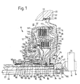
- FIG. 1 shows one in a drive train 10 between a drive unit and a transmission arranged double clutch 12.
- the transmission is in Fig. 1 by a transmission housing bell 18 limiting gear housing section 20 and two gear input shafts 22 and 24, both of which are formed as hollow shafts are, the transmission input shaft 22 is substantially extends coaxially to the transmission input shaft 24 through this.
- a pump drive shaft is arranged inside the transmission input shaft 22, those for driving a transmission-side, not shown in Fig. 1 Oil pump serves, as will be explained in more detail.
- the double clutch 12 is received in the gearbox bell 18, the bell interior towards the drive unit by a Cover 28 is closed, which is pressed into a bell housing opening is and / or is secured therein by a snap ring 30.
- a double clutch like the embodiment shown in Fig. 1, wet running Friction clutches, for example diaphragm clutches, so it is in usually attached, for a sealing engagement between the cover 28 and the clutch housing formed by the transmission housing bell 18 worry, for example by means of an O-ring or other Sealing rings can be made.
- Fig. 1 is a sealing ring 32 with two Sealing lips shown.
- a clutch hub 34 serves as the input side of the double clutch 12 for reasons to be explained in more detail, two fixed to each other Ring sections 36, 38 there.
- the clutch hub 34 extends through a central opening of the cover 28 towards the drive unit and is via an external toothing 42 with the torsional vibration damper, not shown coupled, so that a torque transmission connection between the coupling end 16 of the crankshaft 14 and the clutch hub 34.
- the coupling hub 34 can also directly with the coupling end 16 can be coupled.
- the pump drive shaft 26 has on it from the gear far end on an external toothing 44, which in an internal toothing 46 of the ring portion 36 of the clutch hub 34 engages so that the pump drive shaft 26 rotates with the clutch hub 34 and accordingly drives the oil pump when the clutch hub 34 a rotational movement is given, usually by the drive unit and in some operating situations possibly also from the gearbox over the Double clutch (for example in a by the keyword "engine brake” characterized operating situation).
- the cover 28 extends radially between a radial recess 50 of the bell housing 18 bounding annular peripheral wall portion the bell housing 18 and the ring portion 38 of the hub 34, it being advantageous if between a radially inner wall region 52 of the cover 28 and the hub 34, especially the ring portion 38, one Sealing or / and pivot bearing arrangement 54 is provided, especially if if - as in the embodiment shown - the lid 28 on the Bell housing 18 is fixed and accordingly with the double clutch 12 does not turn. A seal between the lid and the Hub will be particularly necessary if, as with Embodiment, in the clutch arrangements of the double clutch are wet-running clutches.
- a high level of operational safety also in the In the event of oscillations and vibrations occurring is achieved if the seal or / and pivot bearing arrangement 54 axially on the cover 28 or / and is secured to the coupling hub 34, for example by a End portion of the lid edge 52 bent radially inward, as in FIG. 1 can be seen.
- a carrier plate 60 is non-rotatably on the ring section 38 of the hub 34 attached that for torque transmission between the hub 34 and an outer plate carrier 62 - a first plate clutch arrangement 64 serves.
- the outer disk carrier 62 extends in the direction of Gear and radially inward to an annular part 66 on which the outer disk carrier is rotatably attached and that by means of an axial and Radial bearing arrangement 68 on the two transmission input shafts 22 and 24 is mounted such that both radial and axial forces on the Gearbox input shafts are supported.
- the axial and radial bearing arrangement 68 enables relative rotation between the ring part 66 on the one hand and both the transmission input shaft 22 and the transmission input shaft 24 on the other hand. On the structure and how it works the axial and radial bearing arrangement will be discussed in more detail later.
- the disk pack 74 of the disk pack 76 of the first Lamella clutch arrangement is surrounded in a ring.
- the two outer disk carriers 62 and 70 are, as already indicated, through the ring part 66 non-rotatably connected and stand together on the means an external toothing with the outer disk carrier 62 in a positive Torque transmission intervention standing support plate 60 with the Coupling hub 34 and thus - via the torsional vibration damper, not shown - With the crankshaft 14 of the drive unit in a torque transmission connection.
- the outer disk carriers 62 serve from the drive unit to the transmission and 70 each as the input side of the multi-plate clutch arrangement 64 or 72.
- the hub member 80 via the thrust bearing 94 at one end portion the radially outer transmission input shaft 24 is axially supported.
- the hub part 84 can be directly on a ring stop or the like or a separate one Snap ring or the like in the direction of the gearbox on the gearbox input shaft 24 be supported. Since the hub part 84 and the ring part 66 can be rotated relative to one another between these components an axial bearing can be provided, unless the bearing 92 has both as well as radial bearing function. The latter is used in relation to the Embodiment assumed in Fig. 1.
- actuating piston 110 is axially between the radially extending Portion of the outer plate carrier 62 of the first plate clutch arrangement 64 and the radially extending portion of the outer disk carrier 70 of the second multi-plate clutch arrangement 72 arranged and on both outer disk carriers and on the ring part 66 by means of seals 112, 114, 116 axially displaceable and one between the outer disk carrier 62 and the actuating piston 110 Pressure chamber 118 and one between the actuating piston 110 and the centrifugal pressure compensation chamber formed in the outer disk carrier 70 120 performed sealing.
- the pressure chamber 118 is in a the ring part 66 formed pressure medium channel 122 with one at a Pressure medium supply, here the already mentioned oil pump, connected Pressure control device, possibly a control valve, in connection, wherein the pressure medium channel 122 via a possibly receiving the ring part 66 gear-fixed connection sleeve connected to the pressure control device is.
- the ring part 66 should be mentioned in this context that this for easier manufacture, especially with regard to the pressure medium channel 122 and another pressure medium channel made in two parts is with two nested sleeve-like ring sections, as indicated in Fig. 1.
- An actuating piston assigned to the second multi-plate clutch arrangement 72 130 is axially between the outer disk carrier 70 of the second multi-plate clutch assembly 72 and one itself radially extending and at an axial end region remote from the gear of the ring part 66 rotatably and fluid-tightly attached wall part 132 arranged and by means of seals 134, 136 and 138 on the outer disk carrier 70, the wall part 132 and the ring part 66 axially displaceable and one between the outer disk carrier 70 and the operating piston 130 formed pressure chamber 140 and one between the Actuating piston 130 and the wall part 132 formed centrifugal pressure compensation chamber 142 performed sealing.
- the pressure chamber 140 is via a further (already mentioned) pressure medium channel 144 in a corresponding manner Way as the pressure chamber 118 on a / the pressure control device connected.
- the pressure control device can the two pressure chambers 118 and 140 optionally (if necessary also simultaneously) pressure applied by the pressure medium source (here oil pump) to the first multi-plate clutch assembly 64 and / or second multi-plate clutch arrangement 72 in the sense of engagement actuate.
- the pressure medium source here oil pump
- Diaphragm springs 146, 148 of which the actuating piston 130 associated diaphragm spring 148 in the centrifugal pressure compensation chamber 142 is included.
- the pressure chambers 118 and 140 are, at least during normal operating conditions the double clutch 112, completely with pressure medium (here hydraulic oil) filled, and the operating state of the multi-plate clutch assemblies depends on the pressure chamber Media pressure off. But since the outer disk carriers 62 and 70 together with the ring part 66 and the actuating piston 110 and 130 and the Turn wall part 133 with the clutch shaft 14 while driving, it occurs even without applying pressure to the pressure chambers 118 and 140 on the part of the pressure control device to centrifugal pressure increases in the pressure chambers, at least at higher speeds an unwanted engagement or at least grinding of the multi-plate clutch arrangements could lead. For that reason they are centrifugal pressure compensation chambers 120, 142 provided, the record a pressure compensation medium and in which it is in the appropriate Way to centrifugal pressure increases that the in the Compensate pressure chambers occurring centrifugal pressure increases.
- pressure medium here hydraulic oil
- centrifugal pressure compensation chambers 120 and 142 permanently filled with pressure compensation medium, e.g. oil, where necessary, a volume compensation to accommodate in the course of a Actuation of the actuating piston displaced pressure compensation medium could provide.
- pressure compensation medium e.g. oil
- the Centrifugal pressure compensation chambers 120, 142 each only in the operation of the Drive train filled with pressure compensation medium, in connection with the supply of cooling fluid, in the embodiment shown especially cooling oil, to the multi-plate clutch arrangements 64 and 72 one between the ring member 66 and the outer transmission input shaft 24 trained ring channel 150, which is permeable to the cooling oil bearing 90, 92 are attributable.
- the cooling oil flows from a transmission side Connection between the ring part and the transmission input shaft 24 in Direction to the drive unit through the bearing 90 and the bearing 92 and then flows in a partial flow between that of the transmission distal end portion of the ring member 66 and the hub member 84 radially outside in the direction of the disk pack 74 of the second disk clutch arrangement 72, occurs due to passage openings in the inner disk carrier 86 into the area of the slats, flows between the slats of the disk pack 74 or by friction lining grooves or the like of these disks to the outside radially, passes through openings in the outer disk carrier 70 and passage openings in the inner disk carrier 82 in the area of Plate pack 76 of the first plate clutch arrangement 64, flows between the lamellae of this lamellae package or by covering grooves o.
- a pressurizing surface assigned to the pressure chamber 140 of the actuating piston 130 is smaller and moreover less far extends radially outward as one of the pressure compensation chamber 142 associated pressurizing surface of the piston 130 is in the Wall part 132 at least one fill level limiting opening 156 trained the maximum, the required centrifugal force compensation resulting radial fill level of the pressure compensation chamber 142. is the maximum fill level is reached, then that supplied through the bore 154 flows Cooling oil through the level limiting opening 156 and united with the between the ring member 66 and the hub part 84 after radially outward cooling oil flow.
- these are the Pressure chamber 118 and those associated with the pressure compensation chamber 120 Pressurizing surfaces of the piston are the same size and extend in the same radial area, so that for the pressure compensation chamber 120 appropriate level limiting means are not required.
- the piston 110 Since the cooling oil flowing radially outward is adjacent to one another radially outer portion of the associated with the first multi-plate clutch assembly 64 Actuating piston 110 could accumulate and at least at higher speeds due to centrifugal force the engaging movement of this piston could hinder, the piston 110 has at least one pressure compensation opening 162 on that a cooling oil flow from one side of the piston to enables others. Accordingly, it becomes a cluster of Cooling oil on both sides of the piston come with appropriate compensation centrifugal forces on the piston. Further prevents others from interacting with the cooling oil Forces based on the piston the required axial piston movements hinder. Here, for example, hydrodynamic forces or the like. thought as well as "sucking" the piston on the outer disk carrier 62nd
- Cooling oil drain opening in the radial direction extending, radially outer region of the outer disk carrier 62 of the to provide the first multi-plate clutch arrangement 64.
- a cooling oil drain opening is indicated by dashed lines at 164.
- Cooling oil guide element generally a cooling fluid guide element
- In 1 is indicated by dashed lines that an adjacent end lamella 166 of the Plate pack 76 could have a cooling oil guide section 168, so that the end plate 166 itself serves as a cooling oil guide.
- the pressure control device for the Actuation of the two multi-plate clutch arrangements was at the Embodiment of FIG. 1 provided that one for the radially inner Multi-plate clutch assembly 72 based on an actuation pressure given, compared to the other clutch assembly 64 lower Torque transmission capability (due to a lower effective Friction radius as the radially outer clutch arrangement 64) at least partially is compensated.
- the pressure chamber 140 is assigned Pressure area of the piston 130 larger than that of the pressure chamber 118 assigned pressure area of the piston 110, see that with the same hydraulic oil pressure in the pressure chambers on the piston 130 greater axially directed forces than exerted on the piston 110 become.
- the radially inner one (Second) multi-plate clutch arrangement without friction lining i.e. no friction lining bearing plates axially thicker than plate bearing elements of friction-bearing ones Slats formed in order for the frictionless slats respectively a comparatively large volume of material with appropriate heat capacity provided.
- These slats should be made from one material that have a significant heat storage capacity (heat capacity) has, for example made of steel.
- the friction lining-bearing plates can If conventional friction linings are used, for example from Paper, store little heat because paper is bad Has thermal conductivity.
- the heat capacity of the friction lining support elements carrying the friction linings can also be made available as heat storage if instead of covering materials with low conductivity, covering materials used with high conductivity.
- the use comes into consideration of friction linings made of sintered material, which has a comparatively high thermal conductivity Has.
- the problem with the use of sintered coatings is however, that sintered linings show a degressive course of the coefficient of friction ⁇ above a slip speed (relative speed ⁇ N between the rubbing Surfaces), i.e. d ⁇ / d ⁇ N ⁇ 0 applies.
- the coefficient of friction is disadvantageous insofar as it is a self-excitation of Can promote vibrations in the drive train or such vibrations at least cannot dampen.
- the disk set 74 of the radially inner disk clutch arrangement 60 is designed without sintered linings because the radially outer multi-plate clutch arrangement 64 preferably as a starting clutch with the corresponding Slip mode is used.
- the latter i.e. the use of the radial outer multi-plate clutch arrangement as a starting clutch, is so far advantageous than that due to the larger effective friction radius Multi-plate clutch arrangement with lower actuation forces (for the same torque transmission capability) can be operated, so that the surface pressure compared to the second multi-plate clutch arrangement can be reduced.
- This also contributes to the slats of the first multi-plate clutch arrangement 64 with a slightly greater radial height than the plates of the second plate clutch assembly 72 forms.
- the radial can also be used for the disk set 74 inner (second) multi-plate clutch arrangement 72 friction linings made of sintered material are used, preferably - as explained - in combination with friction linings made of another material, such as paper.
- At least the end fins 166 and 168 have a preferred embodiment axially much thicker lining support elements than the lining support elements of the other outer slats and are formed with coverings made of sintered material, around the covering support elements, which have a comparatively large volume of the two end fins can be used as a heat buffer close.
- the plate-free plates are axial thicker than the disk support elements of the friction lining-bearing disks (with Exception of the end lamellas) to a comparatively large heat capacity to provide for intermediate heat storage.
- the axially inside Outer plates should at least partially have friction linings from another have a progressive coefficient of friction material to for the plate pack as a whole at least an approximately neutral one To achieve the coefficient of friction curve above the slip speed.
- FIG. 1 So is the axial bore in the ring portion 36 of the clutch hub 34, in which the internal toothing 46 for the pump drive shaft is formed, sealed oil-tight by a plug 180 fixed therein.
- the carrier plate 60 is on the outer plate carrier 62 by two Retaining rings 172, 174 axially fixed, of which the retaining ring 172 also End plate 170 axially supported.
- a corresponding retaining ring is also for the Support of the disk pack 74 on the outer disk carrier 70 is provided.
- the formation of the outer slats of the first Multi-plate clutch assembly 64 mentioned as lining-carrying plates be that in connection with the assignment of the outer slats to the Input side of the coupling device a better flow of the Plate pack 76 is achieved when the friction linings - as conventional regular practice - with friction lining grooves or other fluid passages are formed which also flow through the plate pack in Allow condition of frictional engagement. Since the input side is also at disengaged clutch assembly with the drive unit or Coupling end 16 rotates when the drive unit is running, it comes about the circumferential friction lining grooves or the circumferential fluid passages a kind of promotional effect with a corresponding better flooding of the Plate pack. Deviating from the illustration in FIG. 1, one could also design the second multi-plate clutch arrangement accordingly, So design the outer plates as friction-bearing plates.
- the first outer disk carrier 62 and the first actuating piston are 110 alternately partially excluded in the circumferential direction, see above that not recessed locations of the actuating piston 110 in recessed Places the outer disk carrier 62 and not excluded Placing the outer disk carrier 62 in recessed positions of the actuating piston 110 intervene.
- the provision of the mentioned anti-rotation device is sensible insofar as an additional burden on the between the outer disk carrier 62 and the actuating piston 110 acting Seals due to microrotations as a result of engine irregularities can be prevented.
- the actuating piston must be used to prevent this rotation 110 and the outer disk carrier 62 also in the indented Interlock the state of the first multi-plate clutch arrangement 64, which would not otherwise be required.
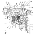
- 1 and 2 is the coupling device via the coupling hub 34 on the drive unit of the drive train coupled, preferably via a torsional vibration damper, as shown in Fig. 2 as an example.
- Torsional vibration damper 300 The combination of a double clutch 12 and one shown in FIG. 2 Torsional vibration damper 300 is characterized by simple assembly in a drivetrain. That of the double clutch and the Torsional vibration damper drive system 11 can thus be formed simply into a drive train between the respective drive unit (Engine) and the gearbox.
- the disc member 304 has tool openings 314 by means of an appropriate tool Bolt 316 can be tightened to the first cover plate Attach 306 to the crankshaft or the coupling end of the crankshaft.
- the primary side of the torsional vibration damper 300 is from one the first cover plate 306 attached to the crankshaft and one attached thereto second cover plate 308 formed, the starter ring gear 310, via the by means of a starter, not shown in the case a drive unit designed as an internal combustion engine started it can be.
- a damper element assembly 312 of the torsional vibration damper 300 is in known manner in recesses of the Disc part 304 between the two cover plates 306 and 308, wherein the cover plates between adjacent in the circumferential direction Dents engaging recesses, support parts or the like have, so that overall for a primary and secondary Support of the damper element arrangement in the circumferential direction is taken care of.
- the damper elements can be arranged with the help of spring Slide shoes and the like are supported and guided.
- drive systems according to the invention 11 comprising a multiple clutch device, especially a double clutch device and a torsional vibration damper assembly and possibly one, for example from a crankshaft starter generator Electrical machine formed are explained with reference to FIGS. 3 to 17.
- the double clutches 12 correspond with regard to their internal structure and their functioning in Essentially the embodiment of FIG. 1, so that on an entry no reference numerals for the different components can be. For the sake of simplicity, it is also omitted to all hatched components shown in a sectional view in the figures display.
- Fig. 1 One skilled in the art will understand from a simple comparison of those Figure with Fig. 1 immediately recognize which components in a Sectional view are shown. The professional will also notice minor differences in the detailed version of the double clutches from the figures detect.
- the torsional vibration damper 300 integrated into the double clutch.
- the coupling hub 34 Radial webs 320, between which the nested damper elements (Damper springs) of the damper element assembly 312 included are.
- the clutch hub 34 serves as the primary side of the torsional vibration damper 300th
- damper elements of the damper element assembly 312 are under the mediation of a sliding element arrangement 322 (for example comprehensively known sliding shoes, Spring plate or other sliding and guide elements) at an angle in radial and axial portions 324 of the torque transmission plate 60 guided, between which defined in the sheet 60 guide tongues 326 are pressed out of the sheet metal in such a way that one in a cross-sectional view according to the figure roof-shaped guide arrangement is created that not only in the circumferential direction, but also in axial direction for guidance and posture.
- a sliding element arrangement 322 for example comprehensively known sliding shoes, Spring plate or other sliding and guide elements
- the drive system 11 has a coupling arrangement, which is used for coupling the double clutch 12 on the drive unit, especially at the coupling end 16 serves the crankshaft.
- the coupling arrangement 320 is of a so-called Flexplatte (flexplate) 332 formed, the radially outside a starter ring gear 310 carries, as the primary additional mass in relation to the Torsional vibration damper 300 acts.
- the flex plate 332 is radially inside with a coupling flange 334 extending in the axial direction, which has an internal toothing for coupling with the external toothing 42 the clutch hub 34.
- the external toothing 42 is shown Embodiment on an axial coupling flange 336 of the coupling hub 34 provided.
- the stationary cover 28 is by means of a pivot bearing arrangement 54, which preferably also fulfills a sealing function, on Coupling flange 334 of the coupling arrangement 330 is mounted.
- first outer disk carrier 62 rotatably and in torque transmission plate supported in both axial directions 60 is located radially on the inside of the coupling flange 334 of the coupling arrangement 330 stored, with the intermediation of a preferably also sealing functions fulfilling slide ring 338, which has an axial leg portion between an axial edge flange 340 of the torque transmission plate 60 and the coupling flange 334 and a radial leg between the edge flange 340 and the coupling hub 34.
- Sealing ring 342 between the coupling end 16 of the crankshaft and the Flex plate 332 is provided, which together with, for example, as a radial shaft seal executed seal and pivot bearing arrangement 54 and possibly due to a possible sealing function of the slide ring 338 the radial and axial area radially within the coupling flange 334, 336 and axially between the coupling hub 34 and the coupling end 16 seals radially on the outside.
- crankshaft an additional mass arrangement in addition to the ring gear 310 could be provided on the flex plate.
- the Flex plate 330 carries the ring gear 310 and, if applicable, an additional mass arrangement. It also forms a running surface for which the rotary bearing 54, possibly the radial shaft sealing ring 54 and serves to establish the drive connection between the input side (clutch hub 34) of the double clutch and the crankshaft, the input side of the double clutch is the primary side of the torsional vibration damper 300 at the same time.
- the Coupling hub 34 decreases in the case of the control torque flow direction the drive unit to the transmission the torque from the flex plate 330 and forms the drive for the torsional vibration damper 300 and the pump shaft 26.
- the outer disk carrier 62 is as well the other plate carriers with flow openings for coolant (cooling oil) executed so that the coolant supplied to the fins radially outside in the receiving space formed by the transmission housing bell 18 can drain, in which the double clutch is installed.
- the roughly on same radial height as the second, radially inner multi-plate clutch arrangement arranged torsional vibration damper 300 is in the from the torque transmission member 60 and the outer plate carrier 62 formed "clutch housing" added, so to speak within an "inner wet room” of the double clutch arranged in the Operation coolant (especially cooling oil) is supplied, so accordingly the torsional vibration damper 300 also works well with coolant is supplied to cool or / and lubricate it.
- coolant especially cooling oil
- the drive unit 11 can be assembled, for example, in this way take place that first the flex plate 330 together with the ring gear 310 and the O-ring 342 is mounted on the engine, and then the cover or Sealing plate 28 together with the radial shaft sealing ring 54 can be mounted.
- the double clutch 12 can be integrated therein Torsional vibration damper 300 as a pre-assembled unit on the transmission to be assembled.
- the gearbox and the motor can be put together including the manufacture of the pivot bearing and sealing connection between the cover 28 and the coupling flange 334 through mediation of the radial shaft sealing ring 54 and the production of the rotary driving connection over the teeth between the two coupling flanges 334 and 336.
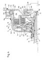
- FIG. 4 Another embodiment of a double clutch 12 with an integrated therein Torsional vibration damper 300 is shown in FIG. 4.
- the double clutch 12 essentially has a Wall 354 consisting of two half-shell parts 350, 352, which is fixed in rotation on the coupling hub 34 and accordingly rotates with the input side of the double clutch 12 or the input side is attributable.
- the wall 354 closes a wet room 356
- Double clutch 12 in which in addition to the multi-plate clutch arrangements 64 and 72 also includes the torsional vibration damper 300.
- the preferably a full fill of coolant, at least in operation, especially cooling oil, receiving wet room 356 is through to the outside an O-ring 358 and a seal and pivot bearing assembly 360, for example, a radial shaft sealing ring, sealed.
- the gearbox side End of the punch shaft 26 receiving one with external teeth internal toothing of the shaft end in rotary driving engagement having through opening of the coupling hub 34 is in the embodiment 4 by a sealing plate welded to the hub 34 180 sealed oil-tight, so far the element 180 of FIG. 1st equivalent.
- the coupling hub 34 is, for example, riveted to it Half shell 350 and the half shell 352 welded to it below Mediation of a slide ring 362 on the outer disk carrier 62 axially in the direction supported to the drive unit. This in turn results in the double clutch axially cohesive closed power flow.
- Radially on the outside A starter ring gear 310 is welded onto the half-shell 350.
- At the Half shell 352 an additional mass ring 364 is welded radially on the outside.
- the starter ring gear 310 and the additional mass ring 364 increase for the Torsional vibration damper 300 is the primary inertial mass.
- the torsional vibration damper acts 300 between the wall 354 and the first outer disk carrier 62, the wall 354 of the primary side and the outer disk carrier 62 assigned to the secondary side of the torsional vibration damper 300 is.
- the two half-shells 350 and 352 form an annular one Guide channel in which a leading the damper element arrangement 312 Sliding element arrangement 322 or the like is accommodated.
- the damper elements are between wall indentations serving to support the force and from the disk support portion 363 of the outer disk support 62 received radially outwardly projecting support webs 366.
- the clutch hub 34 has a (radially outside the crankshaft bolts 316 lying) coupling flange 336 with external teeth on, with an internal toothing of a coupling flange 334 one through attach the bolts (crankshaft bolts) 316 to the coupling end 16 Coupling part 330 is in rotary driving engagement.
- the gears are designed as splines by axial relative movement can be brought into or out of engagement with one another.
- any wobbling movements are mainly through the coupling part 330 and in some Dimensions taken up by the flange 336 of the coupling hub 34, so that on the one hand the coupling end 16 or the crankshaft does not pass through Tumbling movements and the like is burdened, so far none There is a risk of breakage, and also the double clutch and in particular their torsional vibration damper 300 essentially is kept free from wobble movements and wobble forces.
- the wobble occurs essentially only in the area of the splines or the coupling flanges 334, 336.
- the wet room 356 is over between the ring part 66, the transmission input shaft 24, the transmission input shaft 22 and the oil pump drive shaft 26 trained ring channels connected to a cooling oil supply, where, for example (similar to the embodiment of FIG. 1) one formed between the ring member 66 and the transmission input shaft 24 first oil channel and one branching from it, between the Transmission input shaft 24 and the transmission input shaft 22 trained serve and a second oil channel for supplying cooling oil in the wet room 356 between the transmission input shaft 22 and the pump drive shaft 26 trained third oil channel for the removal of cooling oil from the wet room 356 serves.
- a cooling oil circuit can thus be maintained through the wet room 356 can be obtained, which runs through the slats and thus these effectively cools.
- the torsional vibration damper 300 is also in this way reliably supplied with cooling oil.
- the shape of the wall 354 is good with that of the various components of the double clutch 12 ingested Space adjusted so that the wet room 356 in the event of full filling contains comparatively low oil volume and accordingly that moment of inertia attributable to this oil volume is comparatively low is. With the drive train or vehicle stationary, the following may be permitted: that the oil from the radially upper area of the wet room 356 towards to the gearbox and only filled with oil when commissioning becomes.
- the radial shaft seal 360 does not rotate at the engine speed, but rather will only correspond to the relative rotations between the wall 254 and the outer disk carrier 62 together with the ring part 66 Friction charged.
- the torsional vibration damper is located radially outside of the plates of the first plate clutch arrangement 64, whereby - as from the foregoing has already become clear - the torsion damper chamber is formed by a section of the wet space of the double clutch.
- the primary moment of inertia is due to radially outside on the wall 354 additional masses applied (ring gear 210 and mass ring 364) increased, for example with a view to lowering the natural frequency of the system.
- crankshaft For coupling the input side of the double clutch and
- the crankshaft is provided with splines that are radially outside of crankshaft bolts 316 are arranged so that smaller tooth forces occur and the external teeth on flange 336 of the coupling hub 34 is easier to manufacture.
- the support Due to the axial support of the clutch hub 34 over the wall 354 on the outer disk carrier 62 closed power flow reached, the support (slide ring 362) is preferably as far as possible radially inward, to significant tilting moments to avoid.
- the assembly can be done for example in the following way: It will also known as a mounting flange coupling element 330 on the Coupling end 16 of the crankshaft attached.
- the double clutch 12 with the torsional vibration damper 300 integrated therein is preassembled Unit mounted on the gearbox. Then there will be the gearbox and the motor is assembled to create the rotary drive connection on the teeth of the coupling flanges 334, 336.
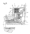
- FIG. 5 corresponds to the integration of the Torsional vibration damper 300 in the double clutch 12 in some Regarding the embodiment of FIG. 3 is the damper element arrangement 312, which in turn are made of radially nested damping elements, in particular compression springs, is formed on the one hand on radial webs 320 one piece with the coupling hub 34 (or alternatively non-rotatably attached) coupling plate 370 and on the other hand via a torque transmission element supported on the outer disk carrier 62.
- Torque transmission member 60 of FIG. 3 corresponding component is used a half shell 350 on the drive unit side, which is connected to the outer disk carrier 62 forming half-shell 352 is connected to the wet room 356 delimiting wall 354 to form.
- the half-shell 350 is like 3 by means of a slide ring 338 on the coupling hub 34 axially supported and on the coupling flange 334 of the coupling arrangement 330 forming flex plate 332 guided radially. Because the wall 354 takes over the function of the cover 28 to a certain extent Sealing a radial shaft ring 54 between the radially inner edge region the half shell 350 and the outer circumference of the coupling flange 334 effective. A sealing washer 180 welded to the coupling flange 334 provides a seal for the oil return path towards the drive unit out.
- the construction of the 5 a full filling of the wet room 356 with coolant, in particular Cooling oil.
- the outer disk carrier 62 is accordingly without oil passage openings executed radially outwards. Instead, is in the area of the holding portion 363 ensures that cooling oil is in sufficient amount can flow radially outside the fins in the axial direction.
- the damper element arrangement 312 receiving torsion damper chamber from a portion of the wet room 356 formed.
- the damper element arrangement is radially outside of the plates of the first plate clutch arrangement 64, so that damper elements with a comparatively large circumferential direction Length can be used.
- the coupling arrangement 330 that applies to the exemplary embodiment of FIG. 3.
- the embodiment in FIG. 6 essentially corresponds to the embodiment of Fig. 5. An important difference is that the Coupling hub 34 in the embodiment of FIG. 6 is made in two parts and of an L flange portion 380 is the primary side of the Torsional vibration damper 300 coupling plate part 370 and an annular part 382 welded to it, which forms the external toothing 42 has.
- the radially inner area of the half-shell part 350 is designed somewhat differently than in the embodiment of FIG. 5, but as there via a radial shaft ring 54 on the coupling flange 334 of the flex plate 352 sealingly guided and by means of a slide ring 338 on the Primary side of the torsional vibration damper 300 axially supported.
- Another slide ring 384 axially supports the coupling disk 370 on the hub part 80 from, the sliding ring 384 optionally having radial grooves to cool oil from the Wet room 356 towards between the pump drive shaft 26 and flow back flow ring channel formed the transmission input shaft 22 allow.
- the two-part design of the coupling hub 34 according to the exemplary embodiment 6 is compared to the one-piece design Fig. 5 advantageous in terms of production technology.
- FIG. 7 essentially corresponds to the embodiment 4. A difference is that the clutch hub 34 with blind bore closed to the drive unit for the Coupling end of the pump drive shaft 26 is designed so that on the Sealing plate 180 can be omitted.
- the coupling between the Coupling end 16 of the crankshaft and the double clutch 12 takes place at Embodiment of FIG. 7 mediated by one of a flex plate 332 formed coupling arrangement 330, which by means of screws 390 in the radial area the damper element arrangement 312, that is to say radially outside of the Sheets of the first multi-plate clutch arrangement 64 on the wall 354 is connected.
- the connection between the drive unit and the double clutch via splines offers the at Construction of Fig.
- the flex plate 332 thus provides optimized wobble decoupling the drive unit is reached by the double clutch.
- the flex plate may differ from the embodiment shown in FIG. 7 also sealing function for wet room 356 and the oil channels take over to the outside and, for example, directly into the wall 354 be involved.
- the rotating with the input side or the outer disk carrier Wall 354 each have a closed housing of the double clutch 12 forms and therefore also addressed as a housing 354 can be.
- a component or components of the double clutch rotating wall is provided, which by itself does not form a closed housing, but together with a stationary wall delimits a wet room. Since one for sealing the wet room between the rotating Wall and the stationary wall regularly required Sealing arrangement or the like comparatively strong on friction is loaded, it is preferred that the double clutch with a closed, rotating housing that the wet room 356 limited.
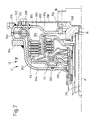
- FIG. 8 Another drive system according to the invention is shown in FIG. 8.
- the double clutch essentially corresponds to the double clutch of FIG. 1 and is with a two-part, the parts 36 and 38 having the coupling hub 34 executed.
- the drive system 11 also includes one Torsional vibration damper 300 and one generally designated 400 Electric machine, for example a so-called crankshaft starter generator.
- the electric machine 400 has a stator arrangement 418 that for example on a stator carrier 420 on a not shown Engine block or the like can be worn.
- Stator assembly 418 includes a stator interaction region 422 having a plurality of Stator windings 424 and a yoke-forming laminated core 426. Die Winding heads 428 of the windings 24 are laterally above the laminated cores 26 about.
- the electric machine 400 further comprises a rotor arrangement 430 with a rotor interaction area 432 and one downstream Carrier assembly 434 described in more detail.
- the rotor interaction region 432 includes a plurality of on the inside thereof worn permanent magnets 436 and laminated cores 438, which are a yoke of the rotor interaction region 432. Between the permanent magnets 36 and the stator interaction area 422 is an air gap 440 formed to maintain the best possible efficiency of the electric machine 400 should be as small as possible.
- the carrier arrangement 434 comprises two carrier elements 442, 444 first support member 442 that is radially outward with a substantially itself radially extending portion 446 the rotor interaction region 432 carries, is in a radially further inward, also essentially radially extending section 448 with the second carrier part 444 by a plurality of rivet bolts which follow one another in the circumferential direction or the like connected.
- Section 448 points the first carrier element 442 in the direction the axis of rotation A and slightly extending radially outwards Connection portion 450, which is with the stator interaction area 422 overlaps in the axial direction or bridges this axially.
- the first carrier element then adjoins this connecting section 450 442 one that essentially extends radially outward again Section 452 on the radially outwards the winding heads 428 bridged and in a substantially axial direction extending, and the winding heads 28 at least partially in the axial direction bridging section 454 passes to which the essentially radially extending section 446 connects.
- a second cover plate area 464 of the primary side is, for example from a separate, for example stamped from sheet metal and suitably shaped element which is substantially radial extending portion 466 which is substantially in the axial direction opposite section 448 of first cover plate region 462.
- the second cover pane area 464 could also of defined in the first carrier element 442 and correspondingly from these pushed out tongue sections or the like. If it is a separate sheet metal part, this can be on the first support element 442 be welded. Also a form-fitting one Snap connection or the like is conceivable.
- particle discharge openings 474 in the transition area between the second cover plate area 64 and the connecting section 450 and particle discharge openings 486 in the transition area between the Sections 452 and 454 are provided.
- a central disk element 480 which is a hub part, serves as the secondary side 302, which is designed with an internal toothing, which in the External teeth 42 engages and so the secondary side of the torsional vibration damper 300 on the input side of the double clutch 12 couples.
- the damper elements are supported in a manner known per se, for example damper springs, the damper element arrangement 312 on the one hand on the primary side, for example on sections 448, 464 and if necessary 450 axial or radial bulges formed, and on the other hand on the secondary side, for example on radial webs of the central disk element 480, with spring plates as support elements for better Pressure distribution can be provided.
- the drive system 11 of FIG. 8 is characterized in that a Function integration for the electric machine and the torsional vibration damper 300 is realized.
- the first carrier element 442 at least the first cover pane region 462 on the primary side forms, the variety of parts is reduced and space is saved. Doing so optimal use of space is achieved by the torsional vibration damper 300 substantially radially within the stator assembly 418 is arranged.
- the rotor arrangement 430 forms a primary mass for the torsional vibration damper 300 while the center plate member 480 together with the components of the double clutch connected to it 12 a secondary mass of the torsional vibration damper 300 forms.
- the outer disk carrier 62 and the outer slats arranged thereon have a significant secondary side Inertial mass.
- the drive system of FIG. 8 is characterized by this from that it is due to a partial merger of the electric machine 400 and the torsional vibration damper 300 very little space claimed.
- the carrier arrangement 434 forms the rotor arrangement 430 a region of the torsional vibration damper which serves to support the force 300, so here, for example, a complete separate Cover plate element or the like can be dispensed with.
- the area 448, 450 of the carrier arrangement 434 which essentially forms the cover plate region 462 of the primary side radially inside the stator arrangement 418 as the external rotor machine trained electric machine 400.
- FIG. 8 The construction of FIG. 8 is based on the following basic concept:
- the Electric machine (crankshaft starter generator) and the torsional vibration damper 300 are nested radially one inside the other, while the double clutch is axially adjacent to it.
- the outside diameter the electric machine is larger than the outer diameter of the double clutch 412, which in the case of a conical shape which corresponds to the normal case Gearbox bell formation (larger inner diameter on the motor side, optimal inner space utilization on the gearbox side) is achieved.
- the double clutch lies with its multi-plate clutch arrangements approximately in the same radial area or radially outside the Torsional vibration damper.
- the torsional vibration damper 300 is intended for dry operation, but it can also be used with executed at least one chamber for the damper element arrangement be a wet-running operation similar to a two-mass flywheel to enable.
- the oil pump and the torsional vibration damper 300 connected in series, so that not only the Double clutch 12, but also the oil pump vibration-damped is driven via the torsional vibration damper 300.
- the assembly is preferably carried out in the following way: A first, from the Stator arrangement 418 and the stator support 420 formed unit and second, from rotor assembly 430 and carrier assembly 434 and the torsional vibration damper 300 formed second unit each mounted as a pre-assembled unit on the drive unit.
- the double clutch 12 as a pre-assembled unit on the transmission in the Gearbox bell 18 mounted and the cover 28 with the arrangement of the radial shaft sealing ring 54 between the radially inner flange of the cover and the coupling hub 36 brought into position.
- the gearbox and the drive unit assembled, the internal toothing of the Hub part 302 of the secondary side and the external toothing 42 of the clutch hub 34 are brought into mutual engagement.
- the drive system 11 of FIG. 9 corresponds with regard to the double clutch 12 and the torsional vibration damper 300 essentially that Embodiment of FIG. 2.
- a starter ring gear 310 is in the shown embodiment but waived.
- points Drive system 11 for example, as a crankshaft stator generator serving electric machine 400, the rotor assembly 430 by means of a support ring or support elements 500 on the cover plates 306, 308 formed primary side of the torsional vibration damper 300 held is.
- a stator carrier 502 attached to the transmission, for example a Cast or drawn part carries the radially outside of the double clutch 12 arranged stator arrangement 418.
- the stator carrier has a radial lower portion 504 and a radially upper portion 506, between which the stator arrangement 418 and the rotor arrangement 430 arranged are.
- the joining gap designated 406 between the stator carrier 502 and the bell housing is sealed.
- a Radial shaft sealing ring 54 between the coupling hub 34 and a radial inner bottle of the stator carrier 502 effective.
- the stator carrier 502 is replaced thus the cover 28 of the embodiment of FIG. 1 and limits the the double clutch receiving receiving space 18, the wet room serves.
- the stator carrier 502 can be attached to the drive unit via dowel pins 510 (Motor) be centered and can be screwed to the drive unit.
- the gear housing can be on the drive unit and / or on the stator carrier be attached, namely radially inside and / or radially outside of Air gap 440 of the electric machine 400.
- the assembly of the drive unit 11 of FIG. 9 is best carried out as follows Way:
- the torsional vibration damper 300 together with the rotor arrangement 430 is mounted on the crankshaft. It then becomes the stator carrier 502 together with the stator arrangement 418 mounted on the drive unit, for which the stator carrier has a guide rail 512 which over the Rotor assembly 430 slides.
- the double clutch is independent of this 12 inserted into the bell housing of the gearbox. After that, that will be Gearbox and the drive unit (the motor) put together, whereby on the one hand the torsional vibration damper with the double clutch coupled gears are brought into mutual engagement and on the other hand, the radial shaft seal 54 properly between the inner flange of the stator carrier 502 and the coupling hub 34 arranged becomes.
- the toothing between the hub part 302 and the clutch hub 34 is arranged radially inside the crankshaft bolts 316 to the radial dimension of the coupling hub 34 and, accordingly, the Keeping the diameter of the radial shaft sealing ring 54 comparatively small, so that friction loss and wear of the radial shaft seal be minimized.
- the torsional vibration damper 300 together with the rotor arrangement 430 and the stator arrangement 418 including the stator carrier 502 as a preassembled unit on the Crankshaft or the engine block are screwed, a radial Locking the rotor arrangement 430 on the one hand and the stator arrangement 418, on the other hand, could advantageously be provided.
- the inner diameter of the Radial shaft sealing ring or its seat on the stator carrier 502 radially outside of the crankshaft screw connection 316 lie around the first cover plate 306 at the coupling end 16 of the crankshaft (otherwise the screws 316 would not be accessible). Regardless of this, the Double clutch 12 mounted on the gearbox. Then the gearbox and the drive unit assembled with screwing of the Gearbox on stator carrier 502.
- FIG. 10 corresponds to the double clutch 12 and the integration of the torsional vibration damper 300 therein essentially the embodiment of FIG. 3, so that on the Comments on this figure can be referenced. Be mentioned should still have the sliding elements and spring shoes 322 in a sliding shell 530 are guided to the at relative rotations between the Coupling hub 34 and the torque transmission member 60 in the torsional vibration damper to minimize the friction that occurs.
- Flexplate 332 has a carrier arrangement 434 screwed to the crankshaft, which carries the rotor assembly 430 of an electric machine 400.
- the Electric machine 400 corresponds to electric machine 400 of FIG. 20 if it is disregarded that, according to FIG.
- the torsional vibration damper 300 is not integrated with the electric machine, but in the double clutch 12 is integrated.
- the carrier arrangement 434 therefore only fulfills this a double function in that it has a coupling flange 334, the toothing with the coupling flange 336 of the coupling hub 34 coupled.
- 22 is also the torsional vibration damper 300 arranged radially within the stator arrangement 418 and partially overlaps axially with it.
- the cover 28 is centered on the transmission by means of dowel pins 532 and in one Joining gap between gearbox and drive unit added. To the Gearbox the sealing gap at 534 is sealed, so that the "outer "Wet room” serving recording space sufficient to the drive unit is sealed.
- the exemplary embodiment is the sealing disk 180 on the coupling flange 334 welded. But it could also be clipped.
- the sliding shell 530 does not necessarily have to be combined with sliding elements and the like , the damping elements, in particular damper springs, can also be included directly in the sliding shell.
- Regarding the between the Cover 28 and the coupling flange 334 arranged radial shaft sealing ring 22 became very large in the embodiment shown in FIG kept low; this is still inside the crankshaft bolts 316. This causes friction losses and wear on the radial shaft sealing ring minimized.
- the carrier 434 serves for the Rotor arrangement 430 simultaneously as an output element for coupling the Input side of the double clutch, that of the primary side of the torsional vibration damper equivalent.
- the clutch hub 34 Mediated by the clutch hub 34 also the drive shaft 26 of the oil pump is coupled to this output element, the torque flow to the pump is not via the torsional vibration damper runs.
- the assembly of the drive system 11 in a drive train can expediently take place, for example, in the following manner: the stator arrangement 418 mounted on the engine block. Then the rotor carrier 434 together with the rotor arrangement 430 attached to it on the Crankshaft mounted. Then the sealing plate 28 with the radial shaft sealing ring 54 positioned and mounted on the engine. Independently of which the double clutch 12 with the torsional vibration damper integrated therein 300 as a pre-assembled unit on the gearbox in the Gearbox bell mounted. Eventually the transmission and the engine assembled to produce the rotary driving connection between the coupling flanges 334 and 336.
- FIG. 11 shows an advantageous development of the drive system 11 or the double clutch 12 of FIG. 7.
- 352 formed coupling housing 354 and with the housing and the outer disk carriers rotating cooling oil
- To be able to discharge the wet room 356 is a stationary one in the wet room Blade carrier 600 arranged with blades 602.
- This scoop carrier is rotatably connected via a bearing hub 604 by means of a toothing 606 connected to the gear housing 20.
- the bearing hub has oil inlet holes 608 on, via the pressure oil supply holes 610 in the clutch housing on pressure oil channels of the ring part 66, which can also be referred to as an oil feed sleeve are connected.
- the cooling oil supplied to the multi-plate clutch arrangement becomes at the latest brought into rotation by the rotating wall 354 by friction.
- the circulating cooling oil flow interacts with the fixed blades 602. Since the blades are arranged obliquely on the circumference of the blade carrier 600 are (see Fig. 12), the oil in the axial direction, namely in Direction towards the gearbox, distracted.
- the oil flows on the fixed Blade carrier 600 by gravity radially inward into one Annular gap 612 of the bearing hub 604.
- the oil collecting plate forms together with assigned blades 602 a collection room open on one side.
- the oil can only flow into the annular gap 612 along the relevant blade 602.
- Oil drain holes 622 through which the draining cooling oil into an oil drain hole 624 of the transmission housing 20 and thus for example in the Oil sump of the gearbox arrives.
- the construction described ensures that this is in the wet room introduced cooling oil can be returned without pressure, so that the level of cooling oil during operation in a radially outer ring area for example, is adjustable so that the lamellae of the radially outer one Do not immerse the couplings in the cooling oil and thus avoid drag torque become.
- the torsional vibration damper assembly 300 it is usually advantageous if their damper elements in an "oil bath" are arranged.
- Deflecting the rotating cooling oil radially inwards or towards the center of the Coupling by means of the blades 602 is particularly easy from FIG. 12 understandable.
- the arrow w represents the direction of rotation of the clutch and with it the oil flow.
- the oil collecting plate 620 from one radially projecting portion of a bearing plate 626 is formed, which can also be seen in FIG. 11. Between the oil collecting plate 620 and an adjacent section of the as substantially closed A blade gap 600 embodied in the wall is formed, the down through a bent bottom portion 628 of the oil collection plate 620 can be essentially closed and upwards in a gap between the blade carrier 600 and the inner surface of the Side portion of the half-shell 352 merges into which the blades 602 protrude.
- holes 630 can be provided in the blade carrier 13 shown in FIG. Fig. 13 shows a settlement of the upper area of the blade carrier 600, and it is the blades 602 recognizable.
- 602 "denotes portions of the blades, from the blade carrier 600 radially into the clutch assembly protrude from the surrounding annular gap.
- the blade carrier 600 and thus also the bearing hub 604 is over Axial bearing 632 or 634 against axial misalignment to the rotating half-shell 352 or to the rotating outer disk carrier 62 of the outer clutch axially supported.
- the thrust bearing 632 supports the bearing plate 626 on the half-shell 352 onwards.
- the primary-side wall 354 is in the gear housing 20 with a the wall rotatably connected bearing sleeve 353 and a radial bearing 636 stored.
- a radial shaft seal 638 seals the dry space 640 outside of the housing 354 opposite the wet room 356.
- the housing half-shell 350 on the coupling hub which can also be designated as a central hub 34 welded, so that a high level of tightness can be reliably achieved.
- the inner disk carrier of the radially outer clutch is at its hub 80 via the axial bearing 98 and via a radial bearing 100 on the clutch hub 34 mounted and is supported via the axial bearing 68 on the hub 84 of the Inner disk carrier of the radially inner clutch.
- On a circlip on the transmission input shaft 22 corresponding to the circlip 96 in accordance with FIG. 1 is dispensed with in the present embodiment, so that a the full double clutch 12 including the housing 354 and the hub 34 comprehensive assembly easy to install on the transmission side is.
- Axial support of this unit in the direction of the drive unit can be done with the intermediation of the flex plate 330.
- the coupling hub 34 is designed with a guide pin 650 which engages in a recess of the coupling end 16 of the crankshaft and so the double clutch is centered in relation to the drive unit.
- an additional mass 364 provided on the primary side can, if desired also as an incremental encoder, e.g. B. used for a speed measurement become.
- a corresponding sensor (possibly speed sensor) 652 can be an opening 654 in the transmission housing 20 protrude into the drying room 640. 656 denotes a connection cable of the sensor.
- 658 seals designated between the Gearbox housing and bearing hub 604 are effective and the pressure oil connections caulk.
- the arrow 660 stands for that in the wet room 356 Cooling oil to be supplied, which is parallel to the transmission input shafts in the axial direction is supplied, approximately as in connection with FIG. 1 was explained.
- 662 denotes a bearing sleeve which defines the annular gap 612 limited and the bearing plate 626 holds.
- FIG. 14 shows a development of the double clutch 12 of FIG. 11, in which this is combined with an electric machine 400.
- a rotor arrangement 430 is welded to the wall 354 radially on the outside Rotor carrier 431 held. It is an electric machine from External rotor type. Accordingly, the stator assembly 418 is radially inside rotor assembly 430.
- a holding flange acts as the stator carrier 417 of the transmission housing 20, the cooling channels 419 for the Cooling of the stator can be carried out.
- the cooling channels can over Hoses are connected to a cooling circuit of the engine. you could also provide a separate cooling circuit for the stator.
- the drive system 12 can be installed as follows: Flex plate 330 screwed to the output shaft 14 (possibly crankshaft 14).
- the stator assembly 418 is attached to the stator carrier.
- the rotor carrier 431 is welded to the housing 354.
- the double clutch 12 together with the housing 354 which rotates during operation and the rotor arrangement 430, together with the one integrated in the wet room Torsional vibration damper and the fixed blade carrier 600, assembled into an installation unit and then as installation unit or Installation module inserted in the gearbox.
- This is the subsystem on the transmission side of the drive system 11 finished, it then only needs the gear on Motor are mounted and the rotor carrier 431 with screw connections a radially outer mounting portion of the flex plate 330 become.
- the axial support of the double clutch in the direction of the drive unit takes place through the intermediation of the flex plate 330, because with regard to the Simple mounting option proposed above on a locking ring corresponding to the retaining ring 96 according to FIG. 1 has been.
- FIG. 15 shows a modification of the drive system 11 of FIG. 14, in which the electric machine 400 (the crankshaft starter generator 400) from Inner rotor type is.
- the rotor arrangement 430 is here directly radially on the outside attached to the half-shell 352.
- the stator assembly 418 is on the transmission housing 20 attached, which provides better cooling for the stator can be achieved.
- the drive system is preferably installed in the manner explained in connection with FIG. 14.
- FIG. 16 Another embodiment of a clutch system according to the invention in combination with an electric machine is shown in FIG. 16.
- the electric machine 400 is designed here as an external rotor machine.
- the 16 construction is based on the above explanations of the other embodiments easily understandable, so that further explanations are not required. Even in the case of construction 16 one could center the coupling hub 34 Provide at the coupling end 16 of the output shaft 14.
- FIG. 17 shows a variant in which the electric machine 400 is used as a machine of the inner rotor type. This construction is also straightforward understandable.
Landscapes
- Engineering & Computer Science (AREA)
- General Engineering & Computer Science (AREA)
- Mechanical Engineering (AREA)
- Power Engineering (AREA)
- Hydraulic Clutches, Magnetic Clutches, Fluid Clutches, And Fluid Joints (AREA)
- Arrangement Of Transmissions (AREA)
- Mechanical Operated Clutches (AREA)
Priority Applications (1)
| Application Number | Priority Date | Filing Date | Title |
|---|---|---|---|
| EP07005654A EP1801446B1 (fr) | 2000-07-17 | 2001-06-01 | Transmission avec un embrayage multiple en association avec un dispositif d'amortissement de vibrations de torsion et, peut-être un moteur électrique |
Applications Claiming Priority (4)
| Application Number | Priority Date | Filing Date | Title |
|---|---|---|---|
| DE10034730 | 2000-07-17 | ||
| DE10034730A DE10034730B4 (de) | 1999-09-30 | 2000-07-17 | Mehrfach-Kupplungseinrichtung, ggf. in Kombination mit einer Torsionsschwingungsdämpferanordnung oder/und einer Elektromaschine |
| DE10115453 | 2001-03-29 | ||
| DE10115453.4A DE10115453B4 (de) | 2001-03-29 | 2001-03-29 | Mehrfach-Kupplungseinrichtung, ggf. in Kombination mit einer Torsionsschwingungsdämpferanordnung oder/und einer Elektromaschine |
Related Child Applications (2)
| Application Number | Title | Priority Date | Filing Date |
|---|---|---|---|
| EP07005654A Division EP1801446B1 (fr) | 2000-07-17 | 2001-06-01 | Transmission avec un embrayage multiple en association avec un dispositif d'amortissement de vibrations de torsion et, peut-être un moteur électrique |
| EP07005654.4 Division-Into | 2007-03-20 |
Publications (4)
| Publication Number | Publication Date |
|---|---|
| EP1174633A2 true EP1174633A2 (fr) | 2002-01-23 |
| EP1174633A3 EP1174633A3 (fr) | 2006-01-11 |
| EP1174633B1 EP1174633B1 (fr) | 2007-03-21 |
| EP1174633B2 EP1174633B2 (fr) | 2013-09-04 |
Family
ID=26006411
Family Applications (1)
| Application Number | Title | Priority Date | Filing Date |
|---|---|---|---|
| EP01112877.4A Expired - Lifetime EP1174633B2 (fr) | 2000-07-17 | 2001-06-01 | Installation d'embrayages multiples |
Country Status (3)
| Country | Link |
|---|---|
| EP (1) | EP1174633B2 (fr) |
| AT (1) | ATE357612T1 (fr) |
| DE (1) | DE50112219D1 (fr) |
Cited By (15)
| Publication number | Priority date | Publication date | Assignee | Title |
|---|---|---|---|---|
| EP1496288A1 (fr) * | 2003-07-07 | 2005-01-12 | BorgWarner Inc. | Amortisseur de vibrations torsionelles |
| FR2879702A1 (fr) | 2004-12-17 | 2006-06-23 | Renault Sas | Systeme d'embrayage humide multiple a flasque d'entrainement integrant une cible emettrice de signaux representatifs de la vitesse de rotation dudit flasque |
| EP1703159A1 (fr) | 2005-03-16 | 2006-09-20 | LuK Lamellen und Kupplungsbau Beteiligungs KG | Procédé de refroidissement d'un embrayage humide et embrayage humide |
| EP1712807A1 (fr) * | 2005-03-17 | 2006-10-18 | Zf Friedrichshafen Ag | Système de transmission de couple |
| WO2006129042A2 (fr) * | 2005-06-03 | 2006-12-07 | Renault S.A.S. | Dispositif d'etancheite pour couvercle d'embrayage |
| EP1882865A2 (fr) * | 2006-07-05 | 2008-01-30 | ZF Friedrichshafen AG | DIspositif d'embrayage pour la boîte de vitesses d'un véhicule |
| WO2008025691A1 (fr) * | 2006-08-26 | 2008-03-06 | Zf Friedrichshafen Ag | Unité d'entraînement hybride |
| WO2008064813A2 (fr) * | 2006-11-30 | 2008-06-05 | Zf Friedrichshafen Ag | Module hybride pour système d'entraînement d'un véhicule |
| WO2008034431A3 (fr) * | 2006-09-20 | 2008-08-28 | Gif Gmbh | Chaîne cinématique avec un arbre d'entraînement principal, et chaîne cinématique pour un véhicule automobile avec un arbre d'entraînement sortant notamment d'un bloc-moteur |
| EP1967752A1 (fr) * | 2007-03-06 | 2008-09-10 | Peugeot Citroën Automobiles S.A. | Embrayage pour véhicule automobile |
| WO2008128695A1 (fr) * | 2007-04-24 | 2008-10-30 | Borgwarner Inc. | Dispositif d'embrayage |
| EP2063144A1 (fr) * | 2007-11-20 | 2009-05-27 | AISIN AI Co., Ltd. | Structure de refroidissement d'un appareil d'embrayage pour transmission |
| WO2011063796A1 (fr) * | 2009-11-24 | 2011-06-03 | Schaeffler Technologies Gmbh & Co. Kg | Dispositif de transfert de couple |
| EP2824348A3 (fr) * | 2013-07-05 | 2016-03-23 | Schaeffler Technologies AG & Co. KG | Embrayage à friction |
| CN111771071A (zh) * | 2018-02-27 | 2020-10-13 | 舍弗勒技术股份两合公司 | 具有附加的支撑轴承的离合器装置以及驱动单元 |
Families Citing this family (1)
| Publication number | Priority date | Publication date | Assignee | Title |
|---|---|---|---|---|
| US8100800B2 (en) * | 2008-04-04 | 2012-01-24 | GM Global Technology Operations LLC | Integrated motor cooling/clutch backfill system for use in a hybrid transmission |
Citations (8)
| Publication number | Priority date | Publication date | Assignee | Title |
|---|---|---|---|---|
| EP0931951A1 (fr) | 1998-01-16 | 1999-07-28 | Ford Global Technologies, Inc. | Embrayage double à plateaux de friction, en particulier pour véhicules automobiles |
| DE19914376A1 (de) | 1998-04-06 | 1999-10-07 | Luk Lamellen & Kupplungsbau | Geteiltes Schwungrad |
| DE10004186A1 (de) | 1999-09-30 | 2001-04-05 | Mannesmann Sachs Ag | Mehrfach-Kupplungseinrichtung |
| DE10004189A1 (de) | 1999-09-30 | 2001-04-05 | Mannesmann Sachs Ag | Mehrfach-Kupplungseinrichtung |
| DE10004190A1 (de) | 1999-09-30 | 2001-04-05 | Mannesmann Sachs Ag | Mehrfach-Kupplungseinrichtung |
| DE10004179A1 (de) | 1999-09-30 | 2001-04-05 | Mannesmann Sachs Ag | Mehrfach-Kupplungseinrichtung |
| DE10004195A1 (de) | 1999-09-30 | 2001-04-05 | Mannesmann Sachs Ag | Mehrfach-Kupplungseinrichtung |
| DE10023113A1 (de) | 2000-02-15 | 2001-08-16 | Mannesmann Sachs Ag | Antriebssystem |
Family Cites Families (25)
| Publication number | Priority date | Publication date | Assignee | Title |
|---|---|---|---|---|
| US2687198A (en) † | 1950-08-03 | 1954-08-24 | Chrysler Corp | Clutch |
| US2884107A (en) † | 1954-11-15 | 1959-04-28 | Web Controls Corp | Oil-cooled electromagnetic brake or clutch |
| DE1111888B (de) † | 1956-06-25 | 1961-07-27 | Borg Warner | Hydraulisch betaetigte Wechsel-Reibungs-kupplung |
| US3366211A (en) † | 1965-09-13 | 1968-01-30 | Mack Trucks | Lubricating system for wet clutches |
| US3610384A (en) † | 1970-06-08 | 1971-10-05 | Borg Warner | Fluid cooled clutch |
| BE788161A (fr) † | 1971-09-10 | 1973-02-28 | Towmotor Corp | Carter d'un embrayage a fluide |
| US3964587A (en) † | 1973-08-02 | 1976-06-22 | Borg-Warner Corporation | Control valve for a wet clutch |
| CA1100425A (fr) † | 1977-12-14 | 1981-05-05 | Edward F. Labuda | Traduction non-disponible |
| DE3047778A1 (de) † | 1980-12-18 | 1982-07-08 | Fichtel & Sachs Ag, 8720 Schweinfurt | Hydraulische kupplungsbremse fuer nasslaufkupplungen |
| FR2544427B1 (fr) † | 1983-04-18 | 1988-10-28 | Valeo | Plateau de pression pour mecanisme d'embrayage, et mecanisme d'embrayage comportant un tel plateau de pression, notamment pour vehicule automobile |
| US4574926A (en) † | 1983-06-28 | 1986-03-11 | John Bubak | Oil cooled and fluid pressure operated clutch assembly |
| FR2557232B1 (fr) † | 1983-12-27 | 1989-06-09 | Valeo | Embrayage multidisque dont la lubrification et le refroidissement sont ameliores |
| FR2583479B1 (fr) † | 1985-06-14 | 1990-01-12 | Valeo | Embrayage a circulation d'huile, notamment pour vehicule automobile |
| GB2191252A (en) * | 1986-06-03 | 1987-12-09 | Automotive Products Plc | Friction clutch |
| DE3838865A1 (de) † | 1987-12-19 | 1989-06-29 | Luk Lamellen & Kupplungsbau | Mehrfachkupplungsaggregat |
| DE3819702A1 (de) * | 1988-06-09 | 1989-12-14 | Porsche Ag | Hydraulisch betaetigte doppelkupplung fuer ein kraftfahrzeug |
| DE9114528U1 (de) * | 1991-11-22 | 1992-02-13 | Zahnradfabrik Friedrichshafen Ag, 7990 Friedrichshafen | Doppelkupplung |
| JPH09229090A (ja) † | 1995-12-18 | 1997-09-02 | Nsk Warner Kk | 発進クラッチ |
| DE19821164B4 (de) * | 1998-05-12 | 2008-04-17 | Volkswagen Ag | Doppelkupplungsgetriebe |
| JP2000035056A (ja) † | 1998-07-17 | 2000-02-02 | Dainatsukusu:Kk | 冷却用油捕集機能を具えた湿式多板クラッチ |
| JP2002523275A (ja) † | 1998-08-21 | 2002-07-30 | ルーク ラメレン ウント クツプルングスバウ ベタイリグングス コマンディートゲゼルシャフト | 駆動系統 |
| DE19921687C5 (de) * | 1999-05-12 | 2016-06-09 | Borgwarner Inc. | Mehrfach-Kupplungssystem für ein Getriebe |
| FR2799251B1 (fr) † | 1999-09-30 | 2006-12-08 | Mannesmann Sachs Ag | Installation d'embrayage multiple de cas echeant en combinaison avec un dispositif amortisseur d'oscillations de torsion ou/et une machine electrique |
| DE10034730B4 (de) * | 1999-09-30 | 2010-10-14 | Zf Sachs Ag | Mehrfach-Kupplungseinrichtung, ggf. in Kombination mit einer Torsionsschwingungsdämpferanordnung oder/und einer Elektromaschine |
| DE50001452D1 (de) * | 2000-10-05 | 2003-04-17 | Ford Global Tech Inc | Doppelkupplung für ein Getriebe mit zwei Getriebeeingangswellen |
-
2001
- 2001-06-01 DE DE50112219T patent/DE50112219D1/de not_active Expired - Lifetime
- 2001-06-01 AT AT01112877T patent/ATE357612T1/de not_active IP Right Cessation
- 2001-06-01 EP EP01112877.4A patent/EP1174633B2/fr not_active Expired - Lifetime
Patent Citations (8)
| Publication number | Priority date | Publication date | Assignee | Title |
|---|---|---|---|---|
| EP0931951A1 (fr) | 1998-01-16 | 1999-07-28 | Ford Global Technologies, Inc. | Embrayage double à plateaux de friction, en particulier pour véhicules automobiles |
| DE19914376A1 (de) | 1998-04-06 | 1999-10-07 | Luk Lamellen & Kupplungsbau | Geteiltes Schwungrad |
| DE10004186A1 (de) | 1999-09-30 | 2001-04-05 | Mannesmann Sachs Ag | Mehrfach-Kupplungseinrichtung |
| DE10004189A1 (de) | 1999-09-30 | 2001-04-05 | Mannesmann Sachs Ag | Mehrfach-Kupplungseinrichtung |
| DE10004190A1 (de) | 1999-09-30 | 2001-04-05 | Mannesmann Sachs Ag | Mehrfach-Kupplungseinrichtung |
| DE10004179A1 (de) | 1999-09-30 | 2001-04-05 | Mannesmann Sachs Ag | Mehrfach-Kupplungseinrichtung |
| DE10004195A1 (de) | 1999-09-30 | 2001-04-05 | Mannesmann Sachs Ag | Mehrfach-Kupplungseinrichtung |
| DE10023113A1 (de) | 2000-02-15 | 2001-08-16 | Mannesmann Sachs Ag | Antriebssystem |
Cited By (27)
| Publication number | Priority date | Publication date | Assignee | Title |
|---|---|---|---|---|
| US7238112B2 (en) | 2003-07-07 | 2007-07-03 | Borgwarner. Inc. | Torsional-vibration damper |
| EP1496288A1 (fr) * | 2003-07-07 | 2005-01-12 | BorgWarner Inc. | Amortisseur de vibrations torsionelles |
| FR2879702A1 (fr) | 2004-12-17 | 2006-06-23 | Renault Sas | Systeme d'embrayage humide multiple a flasque d'entrainement integrant une cible emettrice de signaux representatifs de la vitesse de rotation dudit flasque |
| EP1703159A1 (fr) | 2005-03-16 | 2006-09-20 | LuK Lamellen und Kupplungsbau Beteiligungs KG | Procédé de refroidissement d'un embrayage humide et embrayage humide |
| US7461732B2 (en) | 2005-03-16 | 2008-12-09 | Luk Lamellen Und Kupplungsbau Beteiligungs Kg | Method for cooling a liquid-cooled friction clutch and liquid-cooled friction clutch |
| EP1712807A1 (fr) * | 2005-03-17 | 2006-10-18 | Zf Friedrichshafen Ag | Système de transmission de couple |
| WO2006129042A3 (fr) * | 2005-06-03 | 2007-02-01 | Renault Sa | Dispositif d'etancheite pour couvercle d'embrayage |
| FR2886697A1 (fr) * | 2005-06-03 | 2006-12-08 | Renault Sas | Dispositif d'etancheite pour couvercle d'embrayage |
| WO2006129042A2 (fr) * | 2005-06-03 | 2006-12-07 | Renault S.A.S. | Dispositif d'etancheite pour couvercle d'embrayage |
| EP1882865A2 (fr) * | 2006-07-05 | 2008-01-30 | ZF Friedrichshafen AG | DIspositif d'embrayage pour la boîte de vitesses d'un véhicule |
| EP1882865A3 (fr) * | 2006-07-05 | 2008-02-13 | ZF Friedrichshafen AG | DIspositif d'embrayage pour la boîte de vitesses d'un véhicule |
| WO2008025691A1 (fr) * | 2006-08-26 | 2008-03-06 | Zf Friedrichshafen Ag | Unité d'entraînement hybride |
| WO2008034431A3 (fr) * | 2006-09-20 | 2008-08-28 | Gif Gmbh | Chaîne cinématique avec un arbre d'entraînement principal, et chaîne cinématique pour un véhicule automobile avec un arbre d'entraînement sortant notamment d'un bloc-moteur |
| WO2008064813A3 (fr) * | 2006-11-30 | 2008-07-31 | Zahnradfabrik Friedrichshafen | Module hybride pour système d'entraînement d'un véhicule |
| WO2008064813A2 (fr) * | 2006-11-30 | 2008-06-05 | Zf Friedrichshafen Ag | Module hybride pour système d'entraînement d'un véhicule |
| EP1967752A1 (fr) * | 2007-03-06 | 2008-09-10 | Peugeot Citroën Automobiles S.A. | Embrayage pour véhicule automobile |
| FR2913472A1 (fr) * | 2007-03-06 | 2008-09-12 | Peugeot Citroen Automobiles Sa | Embrayage pour vehicule automobile. |
| WO2008128695A1 (fr) * | 2007-04-24 | 2008-10-30 | Borgwarner Inc. | Dispositif d'embrayage |
| CN101627220B (zh) * | 2007-04-24 | 2014-04-09 | 博格华纳公司 | 离合器安排 |
| EP2063144A1 (fr) * | 2007-11-20 | 2009-05-27 | AISIN AI Co., Ltd. | Structure de refroidissement d'un appareil d'embrayage pour transmission |
| CN102695891A (zh) * | 2009-11-24 | 2012-09-26 | 舍弗勒技术股份两合公司 | 转矩传递装置 |
| WO2011063796A1 (fr) * | 2009-11-24 | 2011-06-03 | Schaeffler Technologies Gmbh & Co. Kg | Dispositif de transfert de couple |
| CN102695891B (zh) * | 2009-11-24 | 2015-06-03 | 舍弗勒技术股份两合公司 | 转矩传递装置 |
| EP2824348A3 (fr) * | 2013-07-05 | 2016-03-23 | Schaeffler Technologies AG & Co. KG | Embrayage à friction |
| EP2824348B1 (fr) | 2013-07-05 | 2018-02-14 | Schaeffler Technologies AG & Co. KG | Embrayage à friction |
| CN111771071A (zh) * | 2018-02-27 | 2020-10-13 | 舍弗勒技术股份两合公司 | 具有附加的支撑轴承的离合器装置以及驱动单元 |
| CN111771071B (zh) * | 2018-02-27 | 2022-09-27 | 舍弗勒技术股份两合公司 | 具有附加的支撑轴承的离合器装置以及驱动单元 |
Also Published As
| Publication number | Publication date |
|---|---|
| EP1174633B2 (fr) | 2013-09-04 |
| ATE357612T1 (de) | 2007-04-15 |
| DE50112219D1 (de) | 2007-05-03 |
| EP1174633A3 (fr) | 2006-01-11 |
| EP1174633B1 (fr) | 2007-03-21 |
Similar Documents
| Publication | Publication Date | Title |
|---|---|---|
| DE10034730B4 (de) | Mehrfach-Kupplungseinrichtung, ggf. in Kombination mit einer Torsionsschwingungsdämpferanordnung oder/und einer Elektromaschine | |
| DE10004186B4 (de) | Mehrfach-Kupplungseinrichtung | |
| DE10004190B4 (de) | Mehrfach-Kupplungseinrichtung | |
| DE10004179C5 (de) | Mehrfach-Kupplungseinrichtung | |
| DE10004189B4 (de) | Mehrfach-Kupplungseinrichtung | |
| DE10004195B4 (de) | Mehrfach-Kupplungseinrichtung | |
| EP3558738B1 (fr) | Module hybride et système de propulsion pour un véhicule automobile | |
| DE112009003882B4 (de) | Hybridmodul für einen Antriebsstrang eines Fahrzeuges | |
| EP3559494B1 (fr) | Module hybride et système de propulsion pour un véhicule automobile | |
| DE10115454A1 (de) | Mehrfach-Kupplungseinrichtung, ggf. in Kombination mit einer Torsionsschwingungsdämpferanordnung oder/und einer Elektromaschine | |
| EP3559491B1 (fr) | Module hybride et système de propulsion pour un véhicule automobile | |
| EP1584830B1 (fr) | Dispositif d'embrayage, en particulier dispositif d'embrayage de démarrage | |
| EP1174631B1 (fr) | Dispositif d'accouplement multiple | |
| EP1174633B1 (fr) | Installation d'embrayages multiples | |
| DE10146606A1 (de) | Mehrfach-Kupplungseinrichtung mit axial nebeneinander angeordneten Lamellen-Kupplungsanordnungen | |
| DE10246839A1 (de) | Hybridfahrzeugantriebsstrang | |
| DE10115453B4 (de) | Mehrfach-Kupplungseinrichtung, ggf. in Kombination mit einer Torsionsschwingungsdämpferanordnung oder/und einer Elektromaschine | |
| WO2002070913A1 (fr) | Systeme d'embrayage | |
| DE10049474A1 (de) | Kupplungseinrichtung | |
| DE10044493B4 (de) | Mehrfach-Kupplungseinrichtung, insbesondere Doppel-Kupplungseinrichtung, für lastschaltbare Getriebe | |
| DE10231405A1 (de) | Kupplungseinrichtung, insbesondere Mehrfach-Kupplungseinrichtung | |
| EP1174632B1 (fr) | Installation d'embrayage multiple en combinaison avec un dispositif amortisseur d'oscillations de torsion ou/et une machine électrique | |
| DE10115504A1 (de) | Mehrfach-Kupplungseinrichtung in Kombination mit einer Torsionsschwingungsdämpferanordnung oder/und einer Elektromaschine | |
| WO2022028642A1 (fr) | Embrayage de séparation actionné par milieu sous pression qui est normalement fermé, comprenant un dispositif d'actionnement qui tourne avec celui-ci et qui chevauche axialement un dispositif amortisseur |
Legal Events
| Date | Code | Title | Description |
|---|---|---|---|
| PUAI | Public reference made under article 153(3) epc to a published international application that has entered the european phase |
Free format text: ORIGINAL CODE: 0009012 |
|
| AK | Designated contracting states |
Kind code of ref document: A2 Designated state(s): AT BE CH CY DE DK ES FI FR GB GR IE IT LI LU MC NL PT SE TR |
|
| AX | Request for extension of the european patent |
Free format text: AL;LT;LV;MK;RO;SI |
|
| RAP1 | Party data changed (applicant data changed or rights of an application transferred) |
Owner name: ZF SACHS AG |
|
| PUAL | Search report despatched |
Free format text: ORIGINAL CODE: 0009013 |
|
| AK | Designated contracting states |
Kind code of ref document: A3 Designated state(s): AT BE CH CY DE DK ES FI FR GB GR IE IT LI LU MC NL PT SE TR |
|
| AX | Request for extension of the european patent |
Extension state: AL LT LV MK RO SI |
|
| 17P | Request for examination filed |
Effective date: 20051224 |
|
| AKX | Designation fees paid |
Designated state(s): AT BE CH CY DE DK ES FI FR GB GR IE IT LI LU MC NL PT SE TR |
|
| GRAP | Despatch of communication of intention to grant a patent |
Free format text: ORIGINAL CODE: EPIDOSNIGR1 |
|
| RTI1 | Title (correction) |
Free format text: MULTIPLE CLUTCH DEVICE |
|
| GRAS | Grant fee paid |
Free format text: ORIGINAL CODE: EPIDOSNIGR3 |
|
| GRAA | (expected) grant |
Free format text: ORIGINAL CODE: 0009210 |
|
| AK | Designated contracting states |
Kind code of ref document: B1 Designated state(s): AT BE CH CY DE DK ES FI FR GB GR IE IT LI LU MC NL PT SE TR |
|
| PG25 | Lapsed in a contracting state [announced via postgrant information from national office to epo] |
Ref country code: FI Free format text: LAPSE BECAUSE OF FAILURE TO SUBMIT A TRANSLATION OF THE DESCRIPTION OR TO PAY THE FEE WITHIN THE PRESCRIBED TIME-LIMIT Effective date: 20070321 Ref country code: IE Free format text: LAPSE BECAUSE OF FAILURE TO SUBMIT A TRANSLATION OF THE DESCRIPTION OR TO PAY THE FEE WITHIN THE PRESCRIBED TIME-LIMIT Effective date: 20070321 Ref country code: NL Free format text: LAPSE BECAUSE OF FAILURE TO SUBMIT A TRANSLATION OF THE DESCRIPTION OR TO PAY THE FEE WITHIN THE PRESCRIBED TIME-LIMIT Effective date: 20070321 |
|
| REG | Reference to a national code |
Ref country code: GB Ref legal event code: FG4D Free format text: NOT ENGLISH |
|
| REG | Reference to a national code |
Ref country code: CH Ref legal event code: EP |
|
| REF | Corresponds to: |
Ref document number: 50112219 Country of ref document: DE Date of ref document: 20070503 Kind code of ref document: P |
|
| REG | Reference to a national code |
Ref country code: IE Ref legal event code: FG4D Free format text: LANGUAGE OF EP DOCUMENT: GERMAN |
|
| GBT | Gb: translation of ep patent filed (gb section 77(6)(a)/1977) |
Effective date: 20070530 |
|
| PG25 | Lapsed in a contracting state [announced via postgrant information from national office to epo] |
Ref country code: SE Free format text: LAPSE BECAUSE OF FAILURE TO SUBMIT A TRANSLATION OF THE DESCRIPTION OR TO PAY THE FEE WITHIN THE PRESCRIBED TIME-LIMIT Effective date: 20070621 |
|
| PG25 | Lapsed in a contracting state [announced via postgrant information from national office to epo] |
Ref country code: ES Free format text: LAPSE BECAUSE OF FAILURE TO SUBMIT A TRANSLATION OF THE DESCRIPTION OR TO PAY THE FEE WITHIN THE PRESCRIBED TIME-LIMIT Effective date: 20070702 |
|
| ET | Fr: translation filed | ||
| PG25 | Lapsed in a contracting state [announced via postgrant information from national office to epo] |
Ref country code: PT Free format text: LAPSE BECAUSE OF FAILURE TO SUBMIT A TRANSLATION OF THE DESCRIPTION OR TO PAY THE FEE WITHIN THE PRESCRIBED TIME-LIMIT Effective date: 20070821 |
|
| NLV1 | Nl: lapsed or annulled due to failure to fulfill the requirements of art. 29p and 29m of the patents act | ||
| REG | Reference to a national code |
Ref country code: IE Ref legal event code: FD4D |
|
| PLBI | Opposition filed |
Free format text: ORIGINAL CODE: 0009260 |
|
| BERE | Be: lapsed |
Owner name: ZF SACHS A.G. Effective date: 20070630 |
|
| PLBI | Opposition filed |
Free format text: ORIGINAL CODE: 0009260 |
|
| 26 | Opposition filed |
Opponent name: BORGWARNER INC. Effective date: 20071129 |
|
| PG25 | Lapsed in a contracting state [announced via postgrant information from national office to epo] |
Ref country code: MC Free format text: LAPSE BECAUSE OF NON-PAYMENT OF DUE FEES Effective date: 20070630 Ref country code: DK Free format text: LAPSE BECAUSE OF FAILURE TO SUBMIT A TRANSLATION OF THE DESCRIPTION OR TO PAY THE FEE WITHIN THE PRESCRIBED TIME-LIMIT Effective date: 20070321 |
|
| PLAZ | Examination of admissibility of opposition: despatch of communication + time limit |
Free format text: ORIGINAL CODE: EPIDOSNOPE2 |
|
| 26 | Opposition filed |
Opponent name: BORGWARNER INC. Effective date: 20071129 Opponent name: LUK LAMELLEN UND KUPPLUNGSBAU BETEILIGUNGS KG Effective date: 20071221 |
|
| PLAX | Notice of opposition and request to file observation + time limit sent |
Free format text: ORIGINAL CODE: EPIDOSNOBS2 |
|
| REG | Reference to a national code |
Ref country code: CH Ref legal event code: PL |
|
| PG25 | Lapsed in a contracting state [announced via postgrant information from national office to epo] |
Ref country code: BE Free format text: LAPSE BECAUSE OF NON-PAYMENT OF DUE FEES Effective date: 20070630 |
|
| PG25 | Lapsed in a contracting state [announced via postgrant information from national office to epo] |
Ref country code: GR Free format text: LAPSE BECAUSE OF FAILURE TO SUBMIT A TRANSLATION OF THE DESCRIPTION OR TO PAY THE FEE WITHIN THE PRESCRIBED TIME-LIMIT Effective date: 20070622 Ref country code: CH Free format text: LAPSE BECAUSE OF NON-PAYMENT OF DUE FEES Effective date: 20070630 Ref country code: IT Free format text: LAPSE BECAUSE OF FAILURE TO SUBMIT A TRANSLATION OF THE DESCRIPTION OR TO PAY THE FEE WITHIN THE PRESCRIBED TIME-LIMIT Effective date: 20070321 Ref country code: LI Free format text: LAPSE BECAUSE OF NON-PAYMENT OF DUE FEES Effective date: 20070630 |
|
| PLAQ | Examination of admissibility of opposition: information related to despatch of communication + time limit deleted |
Free format text: ORIGINAL CODE: EPIDOSDOPE2 |
|
| PLAF | Information modified related to communication of a notice of opposition and request to file observations + time limit |
Free format text: ORIGINAL CODE: EPIDOSCOBS2 |
|
| PG25 | Lapsed in a contracting state [announced via postgrant information from national office to epo] |
Ref country code: AT Free format text: LAPSE BECAUSE OF NON-PAYMENT OF DUE FEES Effective date: 20070601 |
|
| PLBB | Reply of patent proprietor to notice(s) of opposition received |
Free format text: ORIGINAL CODE: EPIDOSNOBS3 |
|
| PG25 | Lapsed in a contracting state [announced via postgrant information from national office to epo] |
Ref country code: CY Free format text: LAPSE BECAUSE OF FAILURE TO SUBMIT A TRANSLATION OF THE DESCRIPTION OR TO PAY THE FEE WITHIN THE PRESCRIBED TIME-LIMIT Effective date: 20070321 |
|
| PG25 | Lapsed in a contracting state [announced via postgrant information from national office to epo] |
Ref country code: LU Free format text: LAPSE BECAUSE OF NON-PAYMENT OF DUE FEES Effective date: 20070601 |
|
| PG25 | Lapsed in a contracting state [announced via postgrant information from national office to epo] |
Ref country code: TR Free format text: LAPSE BECAUSE OF FAILURE TO SUBMIT A TRANSLATION OF THE DESCRIPTION OR TO PAY THE FEE WITHIN THE PRESCRIBED TIME-LIMIT Effective date: 20070321 |
|
| PLAY | Examination report in opposition despatched + time limit |
Free format text: ORIGINAL CODE: EPIDOSNORE2 |
|
| PLAH | Information related to despatch of examination report in opposition + time limit modified |
Free format text: ORIGINAL CODE: EPIDOSCORE2 |
|
| PLBC | Reply to examination report in opposition received |
Free format text: ORIGINAL CODE: EPIDOSNORE3 |
|
| PLAB | Opposition data, opponent's data or that of the opponent's representative modified |
Free format text: ORIGINAL CODE: 0009299OPPO |
|
| R26 | Opposition filed (corrected) |
Opponent name: BORGWARNER, INC. Effective date: 20071129 Opponent name: LUK VERMOEGENSVERWALTUNGSGESELLSCHAFT MBH Effective date: 20071221 |
|
| PLAB | Opposition data, opponent's data or that of the opponent's representative modified |
Free format text: ORIGINAL CODE: 0009299OPPO |
|
| R26 | Opposition filed (corrected) |
Opponent name: LUK VERMOEGENSVERWALTUNGSGESELLSCHAFT MBH Effective date: 20071221 Opponent name: BORGWARNER, INC. Effective date: 20071129 |
|
| RAP2 | Party data changed (patent owner data changed or rights of a patent transferred) |
Owner name: ZF FRIEDRICHSHAFEN AG |
|
| REG | Reference to a national code |
Ref country code: DE Ref legal event code: R081 Ref document number: 50112219 Country of ref document: DE Owner name: ZF FRIEDRICHSHAFEN AG, DE Free format text: FORMER OWNER: ZF SACHS AG, 97424 SCHWEINFURT, DE Effective date: 20121030 |
|
| PGFP | Annual fee paid to national office [announced via postgrant information from national office to epo] |
Ref country code: GB Payment date: 20130529 Year of fee payment: 13 |
|
| PUAH | Patent maintained in amended form |
Free format text: ORIGINAL CODE: 0009272 |
|
| STAA | Information on the status of an ep patent application or granted ep patent |
Free format text: STATUS: PATENT MAINTAINED AS AMENDED |
|
| 27A | Patent maintained in amended form |
Effective date: 20130904 |
|
| AK | Designated contracting states |
Kind code of ref document: B2 Designated state(s): AT BE CH CY DE DK ES FI FR GB GR IE IT LI LU MC NL PT SE TR |
|
| REG | Reference to a national code |
Ref country code: DE Ref legal event code: R102 Ref document number: 50112219 Country of ref document: DE Effective date: 20130904 |
|
| GBPC | Gb: european patent ceased through non-payment of renewal fee |
Effective date: 20140601 |
|
| PG25 | Lapsed in a contracting state [announced via postgrant information from national office to epo] |
Ref country code: GB Free format text: LAPSE BECAUSE OF NON-PAYMENT OF DUE FEES Effective date: 20140601 |
|
| REG | Reference to a national code |
Ref country code: FR Ref legal event code: PLFP Year of fee payment: 16 |
|
| REG | Reference to a national code |
Ref country code: FR Ref legal event code: PLFP Year of fee payment: 17 |
|
| REG | Reference to a national code |
Ref country code: FR Ref legal event code: PLFP Year of fee payment: 18 |
|
| PGFP | Annual fee paid to national office [announced via postgrant information from national office to epo] |
Ref country code: DE Payment date: 20180522 Year of fee payment: 18 |
|
| PGFP | Annual fee paid to national office [announced via postgrant information from national office to epo] |
Ref country code: FR Payment date: 20180411 Year of fee payment: 18 |
|
| REG | Reference to a national code |
Ref country code: DE Ref legal event code: R119 Ref document number: 50112219 Country of ref document: DE |
|
| PG25 | Lapsed in a contracting state [announced via postgrant information from national office to epo] |
Ref country code: DE Free format text: LAPSE BECAUSE OF NON-PAYMENT OF DUE FEES Effective date: 20200101 |
|
| PG25 | Lapsed in a contracting state [announced via postgrant information from national office to epo] |
Ref country code: FR Free format text: LAPSE BECAUSE OF NON-PAYMENT OF DUE FEES Effective date: 20190630 |