EP1172149A1 - Fliessbett-Gegenstrahlmühle - Google Patents
Fliessbett-Gegenstrahlmühle Download PDFInfo
- Publication number
- EP1172149A1 EP1172149A1 EP01114088A EP01114088A EP1172149A1 EP 1172149 A1 EP1172149 A1 EP 1172149A1 EP 01114088 A EP01114088 A EP 01114088A EP 01114088 A EP01114088 A EP 01114088A EP 1172149 A1 EP1172149 A1 EP 1172149A1
- Authority
- EP
- European Patent Office
- Prior art keywords
- grinding
- grinding container
- jet mill
- structural unit
- bed counter
- Prior art date
- Legal status (The legal status is an assumption and is not a legal conclusion. Google has not performed a legal analysis and makes no representation as to the accuracy of the status listed.)
- Granted
Links
- 239000000463 material Substances 0.000 claims abstract description 23
- 238000003860 storage Methods 0.000 claims description 9
- 238000004140 cleaning Methods 0.000 claims description 8
- 239000012530 fluid Substances 0.000 claims description 8
- 230000007704 transition Effects 0.000 claims description 6
- 239000002131 composite material Substances 0.000 abstract 2
- 239000002245 particle Substances 0.000 description 3
- 230000005484 gravity Effects 0.000 description 2
- 238000013459 approach Methods 0.000 description 1
- 238000011109 contamination Methods 0.000 description 1
- 230000001419 dependent effect Effects 0.000 description 1
- 238000009826 distribution Methods 0.000 description 1
- 230000003670 easy-to-clean Effects 0.000 description 1
- 230000002349 favourable effect Effects 0.000 description 1
- 238000005243 fluidization Methods 0.000 description 1
- 238000004519 manufacturing process Methods 0.000 description 1
- 239000000825 pharmaceutical preparation Substances 0.000 description 1
- 229940127557 pharmaceutical product Drugs 0.000 description 1
- 238000007789 sealing Methods 0.000 description 1
- 238000000926 separation method Methods 0.000 description 1
- 238000003466 welding Methods 0.000 description 1
Images



Classifications
-
- B—PERFORMING OPERATIONS; TRANSPORTING
- B02—CRUSHING, PULVERISING, OR DISINTEGRATING; PREPARATORY TREATMENT OF GRAIN FOR MILLING
- B02C—CRUSHING, PULVERISING, OR DISINTEGRATING IN GENERAL; MILLING GRAIN
- B02C23/00—Auxiliary methods or auxiliary devices or accessories specially adapted for crushing or disintegrating not provided for in preceding groups or not specially adapted to apparatus covered by a single preceding group
- B02C23/08—Separating or sorting of material, associated with crushing or disintegrating
- B02C23/16—Separating or sorting of material, associated with crushing or disintegrating with separator defining termination of crushing or disintegrating zone, e.g. screen denying egress of oversize material
-
- B—PERFORMING OPERATIONS; TRANSPORTING
- B02—CRUSHING, PULVERISING, OR DISINTEGRATING; PREPARATORY TREATMENT OF GRAIN FOR MILLING
- B02C—CRUSHING, PULVERISING, OR DISINTEGRATING IN GENERAL; MILLING GRAIN
- B02C19/00—Other disintegrating devices or methods
- B02C19/06—Jet mills
- B02C19/068—Jet mills of the fluidised-bed type
Definitions
- the invention relates to fluidized bed counter-jet mills, which act as classifier mills are trained and relates to the design and arrangement of the components.
- Fluid bed counter jet mills generally consist of a vertical axis cylindrical grinding container, with jet nozzles in the lower part of the grinding container are provided.
- the jet nozzles are directed against each other in such a way that the Grinding material is sucked into the jets and with them is accelerated, due to mutual collisions between the Regrind is crushed by impact.
- the viewing device is in generally designed as a centrifugal classifier, being particles that are finer than the separating grain size are, inside in the rotating paddle wheel of the classifier are transported and separated, whereas particles that are coarser than that Particle size are thrown off the rotating paddle wheel and in Grinding containers remain.
- Such a classifier mill is e.g. known from DE 33 38 138 C2. It is as Fluid bed jet mill designed with one of internals for guiding the Grinding serving jets free grinding chamber, in the bottom area of a Nozzle with a vertical outlet, both for grinding and for Fluidization of the gas jet in the grinding chamber is arranged and up to such a height completely with the comminuting good is filled that good and gas as a fountain less Speed out of the bed, using this fountain for feeding one provided above the surface of the bed, regardless of Impulse of the operated jet emerging from the floor nozzle serves.
- the Mouths in a plane perpendicular to the axis of the floor nozzle a circle coaxial to the axis of the floor nozzle are evenly distributed, and whose axes are at a point on the axis of the floor nozzle below the Cut the plane of the nozzle orifices.
- the viewing device there is arranged in the upper part of the grinding container rotates around a vertical axis.
- the classifier wheel works on the centrifugal force principle and separates sufficiently finely ground material from the regrind and transfers it a fine material discharge arranged above the classifier wheel Grinding container out. Furthermore, one is above the fines discharge arranged storage and drive device for the rotating classifier wheel available.
- the object of the invention is therefore to provide a fluid bed counter jet mill To improve the viewing device so that it is easily accessible, simple and can be cleaned completely without great effort.
- the fluid bed counter jet mill provides a classifier wheel arrangement before, together with the storage and drive device a structural unit forms and is detachably connected to the grinding container.
- a structural unit forms and is detachably connected to the grinding container.
- the unit moveable in relation to the grinding container by means of kinematic devices, that the classifier wheel through the fine material discharge upwards from the Grinding container can be removed.
- the fine material discharge remains with the Grinding container connected.
- the grinding container is therefore not in a plane between the lower part in the the grinding chamber is located and the upper part in which the viewing device is located is shared and made accessible, but the dividing level is located within the range of the viewing device. This has the advantage that not only the Grinding room is fully accessible, but also the viewing device from both outside and inside is accessible.
- the classifying wheel can be pivoted through 180 ° be so that the classifier wheel and the grinding container are optimally accessible and can be easily cleaned.
- the pivoting is achieved by a kinematics, the classifier wheel together with the storage and drive device initially vertically moves above and then by an angle greater than 90 °, preferably rotates up to 180 ° around an axis in the horizontal plane. Ideally, it runs Axis of rotation through the center of mass of the classifier wheel unit, Storage and drive device.
- This opening principle can be advantageous not only in fluid bed counter-jet mills be, but e.g. also for impact mills with a rotating beater be used.
- the classifier wheel is functional due to a rotating one Racket mechanism replaced and the container wall transfers at the level of the racket mechanism the circumference of the housing, the internal impact ribs or grinding tracks.
- the Room with line connection arranged above the rotating racket mechanism serves as a grist inlet.
- the grinding air ring line is for Distribution of the grinding air to the connections of the individual jet nozzles above the Jet nozzles, preferably arranged at the level of the classifier wheel.
- This Arrangement avoids contamination of the grinding air ring line Product dusts.
- grinding air lines are the same Height to the jet nozzles or arranged below, so that it is due to Backflows in the lines for sucking in regrind into the Grinding air ring line has come.
- the connectors of the flexible are possible according to the invention Hose lines on the grinding air ring line opposite the connectors the nozzles arranged offset.
- the staggered arrangement is such that when Loosen the fittings on the nozzles, the hoses due to the Align gravity in a vertical position while loosening the loosened ones Swing the connectors away from the nozzles. This will make the nozzle and the nozzle holder on the grinding container is easily accessible for cleaning purposes.
- the corner weld is in Transition area from cylindrical grinding vessel wall and conical bottom with a flat weld seam on the vertical grinding vessel wall and on the conical wall of the floor.
- annular one Stop plate welded between the grinding vessel wall and the bottom, which on her inner ring surface has a transition contour with a large radius, on which no material can attach and is easy to clean.
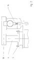
- FIG. 1 shows a cross section of the fluidized bed counter jet mill according to the invention.
- Fig.2 shows the unit of classifier wheel, as well as storage and Drive device in the closed state.
- Fig.3 shows the unit of classifier wheel, as well as storage and Drive device in the open state in the 180 ° position.
- FIG. 4 shows an opening sequence of the kinematics according to the invention.
- Fig. 5 shows a view of the offset grinding air connections.
- FIG 6 shows the stop plate according to the invention.
- FIG 7 shows the opening principle according to the invention on an impact mill.
- the classifier wheel 3 forms together with the classifier wheel bearing 4 and the Drive 14 is a structural unit which, by means of a bearing flange 5 via screws 8 is releasably connected to the mill 15.
- the bearing flange 5 forms one tight seal for the fine material discharge area 1.
- the bearing flange 5 is about a fit 6 centered relative to the mill housing 7.
- the grinding air ring line 16 is on the outside of the mill housing 7 at the level of Classifier wheel 3 attached. Are over the circumference of the grinding air ring line 16 a plurality of connecting pieces 17 are arranged, on which elastic pressure hoses 9 are connected.
- the pressure hoses 9 conduct the via the grinding air ring line 16 Compressed air supplied via connection 21 to each individual jet nozzle 12.
- the pressure hoses 9 are connected to the additional connecting pieces 10 Jet nozzles 12 releasably connected.
- the upper connectors 17 are on the circumference arranged offset relative to the lower connecting pieces 10, so that at Loosen the screw connection 13 on the connecting pieces 10 and the pressure hoses 9 due to gravity swivel into a vertical position and the Open the inlet openings to the jet nozzles 12 (see also Fig. 5).
- Fig. 2 is the structural unit of the bearing flange 5, and bearing 4 - and Drive device 14 can be seen in the closed state.
- the belt drive 18 connects the drive device 14 to the bearing 4 and translates the speed the drive device 14 to a suitable speed for the classifier wheel.
- the pivoting device shown in FIG. 3 enables the structural unit to be rotated of classifier wheel 3, as well as bearing 4 and drive device 14 around the Rotation axis 19 through 180 °.
- the axis of rotation of the classifying wheel 3 is then vertical aligned and the classifier wheel 3 is in an upward open position accessible.
- the distance L and H of the rotary axis 19 from the center of the Cleaning opening 20 is selected so that the cleaning opening 20 is completely free lies and the interior is easily accessible.
- the axis of rotation of the swivel device is preferably in or as close as possible to Mass.
- the rotating working part 26 is included Impact beaters 27 equipped with one on the inner circumference of the grinding containers attached grinding track 28 cooperates.
- the regrind is added via the inlet 29 into the feed chamber 30, from where the regrind to the Impact bat 27 is distributed.
- the sealing 31 of the work spaces takes place between the feed space 30 and the grinding space 32.
Landscapes
- Engineering & Computer Science (AREA)
- Food Science & Technology (AREA)
- Disintegrating Or Milling (AREA)
- Combined Means For Separation Of Solids (AREA)
- Finish Polishing, Edge Sharpening, And Grinding By Specific Grinding Devices (AREA)
- Paper (AREA)
- Crushing And Grinding (AREA)
Abstract
Description
Claims (9)
- Fließbett-Gegenstrahlmühle, bestehend aus:dadurch gekennzeichnet, daß das Sichterrad zusammen mit der Lagerungs- und Antriebseinrichtung eine Baueinheit bildet, die mit dem Mahlbehälter lösbar verbunden ist, wobei die Baueinheit durch kinematische Einrichtungen gegenüber dem Mahlbehälter derart beweglich ist, daß das Sichterrad durch den Feingutaustrag hindurch nach oben aus dem Mahlbehälter entfernt werden kann, wobei der Feingutaustrag weiterhin mit dem Mahlbehälter verbunden bleibt.einem Mahlbehälter zur Aufnahme von Mahlguteiner Anzahl nach innen gerichteter Gegenstrahldüsen, die im unteren Teil des Mahlbehälters angeordnet und derart ausgerichtet sind, daß sich die Strahlen in einem gemeinsamen Punkt treffen, zur Mahlung und Fluidisierung des im Mahlbehälter befindlichen Mahlguteseiner im oberen Teil des Mahlbehälters angeordneten Sichtvorrichtung mit einem um eine vertikale Achse rotierenden, nach dem Zentrifugalkraft-Prinzip arbeitenden Sichterrad, zur Abtrennung von ausreichend fein gemahlenem Gut vom Mahlguteiner Lagerungs- und Antriebseinrichtung für das rotierende Sichterradeiner Gutaufgabe zur Zuführung von Mahlgut in den Mahlbehältereinem oberhalb des Sichterrades angeordneten Feingutaustrag, zum Abführen des abgetrennten, ausreichend fein gemahlenen Gutes aus dem Mahlbehälter
- Fließbett-Gegenstrahlmühle nach Anspruch 1, dadurch gekennzeichnet, daß die Baueinheit von Lagerungs- und Antriebseinrichtung durch eine Hubeinrichtung linear in vertikaler Richtung verschiebbar und durch eine Dreheinrichtung um eine in der vertikalen Ebene liegende Achse schwenkbar ist.
- Fließbett-Gegenstrahlmühle nach Anspruch 2, dadurch gekennzeichnet, daß die Hubeinrichtung ein Hydraulikzylinder und die Dreheinrichtung ein Hydraulikmotor ist.
- Fließbett-Gegenstrahlmühle nach Anspruch 1 bis 3, dadurch gekennzeichnet, daß die Baueinheit von Lagerungs- und Antriebseinrichtung um ihren Massenschwerpunkt schwenkbar ist
- Fließbett-Gegenstrahlmühle nach Anspruch 1 bis 3, dadurch gekennzeichnet, daß die Baueinheit von Lagerungs- und Antriebseinrichtung um 180° schwenkbar ist.
- Fließbett-Gegenstrahlmühle nach Anspruch 1 bis 3, dadurch gekennzeichnet, daß die Lage der Drehachse für die Baueinheit derart gewählt ist, daß nach dem Schwenken der Baueinheit die Reinigungsöffnung vollständig frei liegt.
- Fließbett-Gegenstrahlmühle nach Anspruch 1 bis 3, dadurch gekennzeichnet, daß die Mahlluftringleitung oberhalb der Strahldüsen in Höhe des Sichterrades angeordnet ist.
- Fließbett-Gegenstrahlmühle nach Anspruch 1 bis 3, dadurch gekennzeichnet, daß die Mahlluftanschlüsse an der Mahlluftringleitung am Umfang gegenüber den Mahlluftanschlüssen der Strahldüsen versetzt angeordnet sind.
- Fließbett-Gegenstrahlmühle nach Anspruch 1 bis 3, dadurch gekennzeichnet, daß zwischen der zylindrischen Mahlbehälterwand und dem konischen Mahlbehälterboden eine Anschiagplatte vorgesehen ist, die eine Übergangsrundung am inneren radialen Rand aufweist und mit der zylindrischen Mahlbehälterwand und dem konischen Mahlbehälterboden mit stumpfen Stoß verschweißt ist.
Applications Claiming Priority (2)
| Application Number | Priority Date | Filing Date | Title |
|---|---|---|---|
| DE10033628 | 2000-07-11 | ||
| DE10033628A DE10033628A1 (de) | 2000-07-11 | 2000-07-11 | Fliessbett-Gegenstrahlmühle |
Publications (2)
| Publication Number | Publication Date |
|---|---|
| EP1172149A1 true EP1172149A1 (de) | 2002-01-16 |
| EP1172149B1 EP1172149B1 (de) | 2007-12-26 |
Family
ID=7648523
Family Applications (1)
| Application Number | Title | Priority Date | Filing Date |
|---|---|---|---|
| EP01114088A Expired - Lifetime EP1172149B1 (de) | 2000-07-11 | 2001-06-09 | Fliessbett-Gegenstrahlmühle |
Country Status (6)
| Country | Link |
|---|---|
| US (1) | US6543710B2 (de) |
| EP (1) | EP1172149B1 (de) |
| JP (1) | JP4778636B2 (de) |
| AT (1) | ATE381967T1 (de) |
| DE (2) | DE10033628A1 (de) |
| ES (1) | ES2295085T4 (de) |
Cited By (1)
| Publication number | Priority date | Publication date | Assignee | Title |
|---|---|---|---|---|
| WO2007098778A1 (de) * | 2006-02-24 | 2007-09-07 | Vitrabio Gmbh | Verfahren zur herstellung eines porösen glases und glaspulvers und glaswerkstoff zum ausführen des verfahrens |
Families Citing this family (20)
| Publication number | Priority date | Publication date | Assignee | Title |
|---|---|---|---|---|
| US7449275B2 (en) | 2004-09-21 | 2008-11-11 | Kao Corporation | Process for preparing toner |
| JP2006091175A (ja) | 2004-09-21 | 2006-04-06 | Kao Corp | トナーの製造方法 |
| US7560218B2 (en) | 2004-10-01 | 2009-07-14 | Kao Corporation | Process for preparing toner |
| JP4491328B2 (ja) | 2004-10-29 | 2010-06-30 | 花王株式会社 | トナーの製造方法 |
| US8858699B2 (en) | 2006-07-13 | 2014-10-14 | Unimin Corporation | Ultra fine nepheline syenite powder and products for using same |
| US20080015104A1 (en) * | 2006-07-13 | 2008-01-17 | Unimin Corporation | Ultrafine nepheline syenite |
| US20080040980A1 (en) * | 2006-07-13 | 2008-02-21 | Unimin Corporation | Method of processing nepheline syenite |
| US7757976B2 (en) * | 2007-02-07 | 2010-07-20 | Unimin Corporation | Method of processing nepheline syenite powder to produce an ultra-fine grain size product |
| EP2178645A4 (de) * | 2007-07-09 | 2012-05-02 | Unimin Corp | Nephelinsyenitpulver mit gesteuerter partikelgrösse und neues verfahren zu dessen herstellung |
| JP5246914B2 (ja) | 2007-11-26 | 2013-07-24 | 花王株式会社 | トナーの製造方法 |
| WO2009128857A1 (en) * | 2008-04-17 | 2009-10-22 | Unimin Corporation | Powder formed from mineral or rock material with controlled particle size distribution for thermal films |
| DE102008030749B4 (de) * | 2008-06-27 | 2019-03-07 | Hosokawa Alpine Ag | Mahlvorrichtung mit Mühle als Einbaumodul |
| US8091817B2 (en) * | 2009-12-11 | 2012-01-10 | Flsmidth A/S | Milling device |
| ITMI20120092A1 (it) * | 2012-01-26 | 2013-07-27 | Micro Macinazione S A | Compositi di inclusione farmaco-carrier preparati con processo di attivazione meccano-chimica mediante mulini a getto di fluido ad alta energia |
| DE102018008127B4 (de) | 2018-10-13 | 2022-06-09 | Hosokawa Alpine Aktiengesellschaft | Blaskopf und Verfahren zur Herstellung einer Mehrschichtschlauchfolie |
| DE102018009632B4 (de) | 2018-12-11 | 2021-12-09 | Hosokawa Alpine Aktiengesellschaft | Vorrichtung zum Aufwickeln und Wickelwechsel von bahnförmigem Material und ein Verfahren dafür |
| DE102020000334A1 (de) | 2020-01-21 | 2021-07-22 | Hosokawa Alpine Aktiengesellschaft | Vorrichtung und Verfahren zur monaxialen Längenänderung von Folienbahnen |
| DE102020006008B3 (de) | 2020-10-01 | 2022-03-31 | Hosokawa Alpine Aktiengesellschaft | Fließbettgegenstrahlmühle zur Erzeugung feinster Partikel aus Aufgabegut geringer Schüttdichte und Verfahren dafür |
| CN114011715B (zh) * | 2021-12-14 | 2022-12-06 | 昆山强威粉体设备有限公司 | 流化床对撞式气流粉碎机的分级轮负压出料装置 |
| DE102022000351A1 (de) | 2022-01-29 | 2023-08-03 | Hosokawa Alpine Aktiengesellschaft | Verfahren und Vorrichtung zur Foliendickenregelung von gereckter im Folienblasverfahren hergestellter Schlauchfolie |
Citations (3)
| Publication number | Priority date | Publication date | Assignee | Title |
|---|---|---|---|---|
| DE3140294A1 (de) * | 1981-10-10 | 1983-04-28 | Alpine Ag, 8900 Augsburg | Verfahren und vorrichtung zum trennen eines gutgemisches in komponenten unterschiedlicher mahlbarkeit |
| DE3338138A1 (de) * | 1983-10-20 | 1985-05-09 | Alpine Ag, 8900 Augsburg | Fliessbett-gegenstrahlmuehle |
| DE4100338A1 (de) * | 1991-01-08 | 1992-07-09 | Nied Roland | Verfahren zum ermitteln des grades der befuellung eines behaelters |
Family Cites Families (8)
| Publication number | Priority date | Publication date | Assignee | Title |
|---|---|---|---|---|
| US4018388A (en) * | 1976-05-13 | 1977-04-19 | Andrews Norwood H | Jet-type axial pulverizer |
| DE2641620C3 (de) * | 1976-09-16 | 1987-07-09 | Krupp Polysius Ag, 4720 Beckum | Rollenmühle mit Sichter |
| JPH074557B2 (ja) * | 1990-10-23 | 1995-01-25 | 株式会社栗本鐵工所 | 粉砕媒体を使用した気流粉砕方法 |
| JPH05212308A (ja) * | 1992-01-31 | 1993-08-24 | Fuji Xerox Co Ltd | 微粉砕装置および粉砕方法 |
| JPH0615193A (ja) * | 1992-04-07 | 1994-01-25 | Kyowa Shokuhin:Kk | ジェットミル |
| JP3179389B2 (ja) * | 1997-10-09 | 2001-06-25 | ホソカワミクロン株式会社 | 分級機 |
| JP2000140674A (ja) * | 1998-11-13 | 2000-05-23 | Iec:Kk | 気流式粉砕機 |
| US6398139B1 (en) * | 1999-08-23 | 2002-06-04 | Roland Nied | Process for fluidized-bed jet milling, device for carrying out this process and unit with such a device for carrying out this process |
-
2000
- 2000-07-11 DE DE10033628A patent/DE10033628A1/de not_active Withdrawn
-
2001
- 2001-06-09 DE DE50113409T patent/DE50113409D1/de not_active Expired - Lifetime
- 2001-06-09 EP EP01114088A patent/EP1172149B1/de not_active Expired - Lifetime
- 2001-06-09 AT AT01114088T patent/ATE381967T1/de not_active IP Right Cessation
- 2001-06-09 ES ES01114088T patent/ES2295085T4/es not_active Expired - Lifetime
- 2001-07-09 US US09/901,395 patent/US6543710B2/en not_active Expired - Lifetime
- 2001-07-09 JP JP2001208449A patent/JP4778636B2/ja not_active Expired - Lifetime
Patent Citations (4)
| Publication number | Priority date | Publication date | Assignee | Title |
|---|---|---|---|---|
| DE3140294A1 (de) * | 1981-10-10 | 1983-04-28 | Alpine Ag, 8900 Augsburg | Verfahren und vorrichtung zum trennen eines gutgemisches in komponenten unterschiedlicher mahlbarkeit |
| DE3338138A1 (de) * | 1983-10-20 | 1985-05-09 | Alpine Ag, 8900 Augsburg | Fliessbett-gegenstrahlmuehle |
| DE3338138C2 (de) | 1983-10-20 | 1986-01-16 | Alpine Ag, 8900 Augsburg | Fließbett-Gegenstrahlmühle |
| DE4100338A1 (de) * | 1991-01-08 | 1992-07-09 | Nied Roland | Verfahren zum ermitteln des grades der befuellung eines behaelters |
Cited By (1)
| Publication number | Priority date | Publication date | Assignee | Title |
|---|---|---|---|---|
| WO2007098778A1 (de) * | 2006-02-24 | 2007-09-07 | Vitrabio Gmbh | Verfahren zur herstellung eines porösen glases und glaspulvers und glaswerkstoff zum ausführen des verfahrens |
Also Published As
| Publication number | Publication date |
|---|---|
| ES2295085T3 (es) | 2008-04-16 |
| ES2295085T4 (es) | 2008-06-16 |
| US6543710B2 (en) | 2003-04-08 |
| JP4778636B2 (ja) | 2011-09-21 |
| US20020011534A1 (en) | 2002-01-31 |
| DE10033628A1 (de) | 2002-01-24 |
| DE50113409D1 (de) | 2008-02-07 |
| ATE381967T1 (de) | 2008-01-15 |
| JP2002035631A (ja) | 2002-02-05 |
| EP1172149B1 (de) | 2007-12-26 |
Similar Documents
| Publication | Publication Date | Title |
|---|---|---|
| EP1172149B1 (de) | Fliessbett-Gegenstrahlmühle | |
| DE3338138C2 (de) | Fließbett-Gegenstrahlmühle | |
| DE19635500B4 (de) | Vorrichtung zur Hochenergie- und/oder Feinstmahlung von Feststoffen und Verfahren zu dessen Betrieb | |
| DE2550879C3 (de) | Vorrichtung zur bekannten Wiederverwertung des Abfalls von wärmegehärtetem Kunststoff | |
| WO2012055388A2 (de) | Rührwerkskugelmühle | |
| EP3615236B1 (de) | System von einer industriellen mischmaschine, umfassend einen mischkopf und einen reinigungscontainer | |
| DE19504540A1 (de) | Vorrichtung zum Beschichten oder Entleeren eines Behälters, insbesondere eines mit Mahlkörpern diskontinuierlich arbeitenden Mahlaggregats | |
| DE3140294A1 (de) | Verfahren und vorrichtung zum trennen eines gutgemisches in komponenten unterschiedlicher mahlbarkeit | |
| DE19913243A1 (de) | Mahlvorrichtung zur Hochenergie- und/oder Feinstmahlung von Feststoffen mit schwenkbarem Mahlbehälter | |
| DE3490555C2 (de) | ||
| DE3308390C2 (de) | Schleifzerkleinerer | |
| DE4402609C2 (de) | Rührwerkskugelmühle | |
| DE3222890A1 (de) | Pulvermuehlen-vorrichtung | |
| DE3131370C2 (de) | ||
| DE3730597C2 (de) | Strahlmühle | |
| DE7300113U (de) | Muehle zur feinzerkleinerung von partikelfoermigem material | |
| DE19718668A1 (de) | Verfahren zum Trennen und kontinuierlichen Austragen von schwer dispergierbaren Bestandteilen | |
| DE1288888B (de) | Vorrichtung zum Mahlen von stueckigem Gut | |
| DE19912594B4 (de) | Vorrichtung zur Hochenergie- und/oder Feinstmahlung von Feststoffen | |
| CN223337470U (zh) | 一种方便清理出料器的气流粉碎机 | |
| DE102022129283B4 (de) | Dosiervorrichtungen für Schüttgut, System aufweisend eine solche Dosiervorrichtung und Verfahren zur Reinigung einer Dosiervorrichtung | |
| DE4214060C2 (de) | ||
| DE202018104177U1 (de) | Mischcontainerreinigungsanlage | |
| DE1607489C (de) | Strahlmühle zum Zerkleinern fester Teilchen | |
| AT101054B (de) | Mühle mit Luftsichtung. |
Legal Events
| Date | Code | Title | Description |
|---|---|---|---|
| PUAI | Public reference made under article 153(3) epc to a published international application that has entered the european phase |
Free format text: ORIGINAL CODE: 0009012 |
|
| AK | Designated contracting states |
Kind code of ref document: A1 Designated state(s): AT BE CH CY DE DK ES FI FR GB GR IE IT LI LU MC NL PT SE TR |
|
| AX | Request for extension of the european patent |
Free format text: AL;LT;LV;MK;RO;SI |
|
| 17P | Request for examination filed |
Effective date: 20011220 |
|
| AKX | Designation fees paid |
Free format text: AT BE CH CY DE DK ES FI FR GB GR IE IT LI LU MC NL PT SE TR |
|
| RAP1 | Party data changed (applicant data changed or rights of an application transferred) |
Owner name: HOSOKAWA ALPINE AKTIENGESELLSCHAFT |
|
| GRAP | Despatch of communication of intention to grant a patent |
Free format text: ORIGINAL CODE: EPIDOSNIGR1 |
|
| GRAS | Grant fee paid |
Free format text: ORIGINAL CODE: EPIDOSNIGR3 |
|
| GRAA | (expected) grant |
Free format text: ORIGINAL CODE: 0009210 |
|
| AK | Designated contracting states |
Kind code of ref document: B1 Designated state(s): AT BE CH CY DE DK ES FI FR GB GR IE IT LI LU MC NL PT SE TR |
|
| REG | Reference to a national code |
Ref country code: GB Ref legal event code: FG4D Free format text: NOT ENGLISH |
|
| REG | Reference to a national code |
Ref country code: IE Ref legal event code: FG4D Free format text: LANGUAGE OF EP DOCUMENT: GERMAN |
|
| REG | Reference to a national code |
Ref country code: CH Ref legal event code: EP Ref country code: CH Ref legal event code: NV Representative=s name: LUCHS & PARTNER PATENTANWAELTE |
|
| REF | Corresponds to: |
Ref document number: 50113409 Country of ref document: DE Date of ref document: 20080207 Kind code of ref document: P |
|
| REG | Reference to a national code |
Ref country code: ES Ref legal event code: FG2A Ref document number: 2295085 Country of ref document: ES Kind code of ref document: T3 |
|
| GBT | Gb: translation of ep patent filed (gb section 77(6)(a)/1977) |
Effective date: 20080403 |
|
| PG25 | Lapsed in a contracting state [announced via postgrant information from national office to epo] |
Ref country code: SE Free format text: LAPSE BECAUSE OF FAILURE TO SUBMIT A TRANSLATION OF THE DESCRIPTION OR TO PAY THE FEE WITHIN THE PRESCRIBED TIME-LIMIT Effective date: 20080326 |
|
| PG25 | Lapsed in a contracting state [announced via postgrant information from national office to epo] |
Ref country code: FI Free format text: LAPSE BECAUSE OF FAILURE TO SUBMIT A TRANSLATION OF THE DESCRIPTION OR TO PAY THE FEE WITHIN THE PRESCRIBED TIME-LIMIT Effective date: 20071226 |
|
| PG25 | Lapsed in a contracting state [announced via postgrant information from national office to epo] |
Ref country code: PT Free format text: LAPSE BECAUSE OF FAILURE TO SUBMIT A TRANSLATION OF THE DESCRIPTION OR TO PAY THE FEE WITHIN THE PRESCRIBED TIME-LIMIT Effective date: 20080526 |
|
| PG25 | Lapsed in a contracting state [announced via postgrant information from national office to epo] |
Ref country code: DK Free format text: LAPSE BECAUSE OF FAILURE TO SUBMIT A TRANSLATION OF THE DESCRIPTION OR TO PAY THE FEE WITHIN THE PRESCRIBED TIME-LIMIT Effective date: 20071226 |
|
| PGFP | Annual fee paid to national office [announced via postgrant information from national office to epo] |
Ref country code: IE Payment date: 20080508 Year of fee payment: 8 Ref country code: NL Payment date: 20080610 Year of fee payment: 8 |
|
| PLBE | No opposition filed within time limit |
Free format text: ORIGINAL CODE: 0009261 |
|
| STAA | Information on the status of an ep patent application or granted ep patent |
Free format text: STATUS: NO OPPOSITION FILED WITHIN TIME LIMIT |
|
| 26N | No opposition filed |
Effective date: 20080929 |
|
| BERE | Be: lapsed |
Owner name: HOSOKAWA ALPINE A.G. Effective date: 20080630 |
|
| PGFP | Annual fee paid to national office [announced via postgrant information from national office to epo] |
Ref country code: GB Payment date: 20080512 Year of fee payment: 8 |
|
| PG25 | Lapsed in a contracting state [announced via postgrant information from national office to epo] |
Ref country code: GR Free format text: LAPSE BECAUSE OF FAILURE TO SUBMIT A TRANSLATION OF THE DESCRIPTION OR TO PAY THE FEE WITHIN THE PRESCRIBED TIME-LIMIT Effective date: 20080327 Ref country code: MC Free format text: LAPSE BECAUSE OF NON-PAYMENT OF DUE FEES Effective date: 20080630 |
|
| PG25 | Lapsed in a contracting state [announced via postgrant information from national office to epo] |
Ref country code: BE Free format text: LAPSE BECAUSE OF NON-PAYMENT OF DUE FEES Effective date: 20080630 |
|
| PG25 | Lapsed in a contracting state [announced via postgrant information from national office to epo] |
Ref country code: CY Free format text: LAPSE BECAUSE OF FAILURE TO SUBMIT A TRANSLATION OF THE DESCRIPTION OR TO PAY THE FEE WITHIN THE PRESCRIBED TIME-LIMIT Effective date: 20071226 |
|
| PG25 | Lapsed in a contracting state [announced via postgrant information from national office to epo] |
Ref country code: AT Free format text: LAPSE BECAUSE OF NON-PAYMENT OF DUE FEES Effective date: 20080609 |
|
| GBPC | Gb: european patent ceased through non-payment of renewal fee |
Effective date: 20090609 |
|
| NLV4 | Nl: lapsed or anulled due to non-payment of the annual fee |
Effective date: 20100101 |
|
| PG25 | Lapsed in a contracting state [announced via postgrant information from national office to epo] |
Ref country code: IE Free format text: LAPSE BECAUSE OF NON-PAYMENT OF DUE FEES Effective date: 20090609 |
|
| PG25 | Lapsed in a contracting state [announced via postgrant information from national office to epo] |
Ref country code: GB Free format text: LAPSE BECAUSE OF NON-PAYMENT OF DUE FEES Effective date: 20090609 |
|
| PG25 | Lapsed in a contracting state [announced via postgrant information from national office to epo] |
Ref country code: NL Free format text: LAPSE BECAUSE OF NON-PAYMENT OF DUE FEES Effective date: 20100101 Ref country code: LU Free format text: LAPSE BECAUSE OF NON-PAYMENT OF DUE FEES Effective date: 20080609 |
|
| PG25 | Lapsed in a contracting state [announced via postgrant information from national office to epo] |
Ref country code: TR Free format text: LAPSE BECAUSE OF FAILURE TO SUBMIT A TRANSLATION OF THE DESCRIPTION OR TO PAY THE FEE WITHIN THE PRESCRIBED TIME-LIMIT Effective date: 20071226 |
|
| PGFP | Annual fee paid to national office [announced via postgrant information from national office to epo] |
Ref country code: CH Payment date: 20110614 Year of fee payment: 11 |
|
| REG | Reference to a national code |
Ref country code: CH Ref legal event code: PL |
|
| REG | Reference to a national code |
Ref country code: CH Ref legal event code: PL |
|
| PG25 | Lapsed in a contracting state [announced via postgrant information from national office to epo] |
Ref country code: CH Free format text: LAPSE BECAUSE OF NON-PAYMENT OF DUE FEES Effective date: 20120630 Ref country code: LI Free format text: LAPSE BECAUSE OF NON-PAYMENT OF DUE FEES Effective date: 20120630 |
|
| REG | Reference to a national code |
Ref country code: FR Ref legal event code: PLFP Year of fee payment: 15 |
|
| PGFP | Annual fee paid to national office [announced via postgrant information from national office to epo] |
Ref country code: ES Payment date: 20150512 Year of fee payment: 15 |
|
| PGFP | Annual fee paid to national office [announced via postgrant information from national office to epo] |
Ref country code: FR Payment date: 20150608 Year of fee payment: 15 |
|
| PGFP | Annual fee paid to national office [announced via postgrant information from national office to epo] |
Ref country code: IT Payment date: 20160621 Year of fee payment: 16 |
|
| REG | Reference to a national code |
Ref country code: FR Ref legal event code: ST Effective date: 20170228 |
|
| PG25 | Lapsed in a contracting state [announced via postgrant information from national office to epo] |
Ref country code: FR Free format text: LAPSE BECAUSE OF NON-PAYMENT OF DUE FEES Effective date: 20160630 |
|
| PGFP | Annual fee paid to national office [announced via postgrant information from national office to epo] |
Ref country code: DE Payment date: 20170605 Year of fee payment: 17 |
|
| PG25 | Lapsed in a contracting state [announced via postgrant information from national office to epo] |
Ref country code: IT Free format text: LAPSE BECAUSE OF NON-PAYMENT OF DUE FEES Effective date: 20170609 Ref country code: ES Free format text: LAPSE BECAUSE OF NON-PAYMENT OF DUE FEES Effective date: 20160610 |
|
| REG | Reference to a national code |
Ref country code: ES Ref legal event code: FD2A Effective date: 20181130 |
|
| REG | Reference to a national code |
Ref country code: DE Ref legal event code: R119 Ref document number: 50113409 Country of ref document: DE |
|
| PG25 | Lapsed in a contracting state [announced via postgrant information from national office to epo] |
Ref country code: DE Free format text: LAPSE BECAUSE OF NON-PAYMENT OF DUE FEES Effective date: 20190101 |