EP1171333B1 - Verfahren und vorrichtung zum überwachen oder zum beeinflussen der bewegung eines fahrzeugs auf einem weg - Google Patents
Verfahren und vorrichtung zum überwachen oder zum beeinflussen der bewegung eines fahrzeugs auf einem weg Download PDFInfo
- Publication number
- EP1171333B1 EP1171333B1 EP00917047A EP00917047A EP1171333B1 EP 1171333 B1 EP1171333 B1 EP 1171333B1 EP 00917047 A EP00917047 A EP 00917047A EP 00917047 A EP00917047 A EP 00917047A EP 1171333 B1 EP1171333 B1 EP 1171333B1
- Authority
- EP
- European Patent Office
- Prior art keywords
- movement
- path
- vehicle
- determining
- nominal
- Prior art date
- Legal status (The legal status is an assumption and is not a legal conclusion. Google has not performed a legal analysis and makes no representation as to the accuracy of the status listed.)
- Expired - Lifetime
Links
- 230000033001 locomotion Effects 0.000 title claims description 88
- 238000000034 method Methods 0.000 title claims description 27
- 238000012544 monitoring process Methods 0.000 title claims description 11
- 230000005540 biological transmission Effects 0.000 claims description 15
- 238000010835 comparative analysis Methods 0.000 claims description 10
- 238000013213 extrapolation Methods 0.000 claims description 5
- 230000001133 acceleration Effects 0.000 claims description 3
- 239000012530 fluid Substances 0.000 claims description 3
- 230000003287 optical effect Effects 0.000 claims description 3
- 230000003247 decreasing effect Effects 0.000 claims 1
- 239000011888 foil Substances 0.000 claims 1
- 238000010586 diagram Methods 0.000 description 4
- 230000000052 comparative effect Effects 0.000 description 2
- 230000001419 dependent effect Effects 0.000 description 2
- 238000011156 evaluation Methods 0.000 description 2
- 238000001514 detection method Methods 0.000 description 1
- 230000000694 effects Effects 0.000 description 1
- 230000001902 propagating effect Effects 0.000 description 1
- 230000002123 temporal effect Effects 0.000 description 1
Images


Classifications
-
- B—PERFORMING OPERATIONS; TRANSPORTING
- B60—VEHICLES IN GENERAL
- B60T—VEHICLE BRAKE CONTROL SYSTEMS OR PARTS THEREOF; BRAKE CONTROL SYSTEMS OR PARTS THEREOF, IN GENERAL; ARRANGEMENT OF BRAKING ELEMENTS ON VEHICLES IN GENERAL; PORTABLE DEVICES FOR PREVENTING UNWANTED MOVEMENT OF VEHICLES; VEHICLE MODIFICATIONS TO FACILITATE COOLING OF BRAKES
- B60T8/00—Arrangements for adjusting wheel-braking force to meet varying vehicular or ground-surface conditions, e.g. limiting or varying distribution of braking force
- B60T8/17—Using electrical or electronic regulation means to control braking
- B60T8/1755—Brake regulation specially adapted to control the stability of the vehicle, e.g. taking into account yaw rate or transverse acceleration in a curve
- B60T8/17557—Brake regulation specially adapted to control the stability of the vehicle, e.g. taking into account yaw rate or transverse acceleration in a curve specially adapted for lane departure prevention
-
- B—PERFORMING OPERATIONS; TRANSPORTING
- B60—VEHICLES IN GENERAL
- B60T—VEHICLE BRAKE CONTROL SYSTEMS OR PARTS THEREOF; BRAKE CONTROL SYSTEMS OR PARTS THEREOF, IN GENERAL; ARRANGEMENT OF BRAKING ELEMENTS ON VEHICLES IN GENERAL; PORTABLE DEVICES FOR PREVENTING UNWANTED MOVEMENT OF VEHICLES; VEHICLE MODIFICATIONS TO FACILITATE COOLING OF BRAKES
- B60T7/00—Brake-action initiating means
- B60T7/12—Brake-action initiating means for automatic initiation; for initiation not subject to will of driver or passenger
- B60T7/22—Brake-action initiating means for automatic initiation; for initiation not subject to will of driver or passenger initiated by contact of vehicle, e.g. bumper, with an external object, e.g. another vehicle, or by means of contactless obstacle detectors mounted on the vehicle
-
- B—PERFORMING OPERATIONS; TRANSPORTING
- B60—VEHICLES IN GENERAL
- B60T—VEHICLE BRAKE CONTROL SYSTEMS OR PARTS THEREOF; BRAKE CONTROL SYSTEMS OR PARTS THEREOF, IN GENERAL; ARRANGEMENT OF BRAKING ELEMENTS ON VEHICLES IN GENERAL; PORTABLE DEVICES FOR PREVENTING UNWANTED MOVEMENT OF VEHICLES; VEHICLE MODIFICATIONS TO FACILITATE COOLING OF BRAKES
- B60T8/00—Arrangements for adjusting wheel-braking force to meet varying vehicular or ground-surface conditions, e.g. limiting or varying distribution of braking force
- B60T8/17—Using electrical or electronic regulation means to control braking
- B60T8/174—Using electrical or electronic regulation means to control braking characterised by using special control logic, e.g. fuzzy logic, neural computing
-
- B—PERFORMING OPERATIONS; TRANSPORTING
- B62—LAND VEHICLES FOR TRAVELLING OTHERWISE THAN ON RAILS
- B62D—MOTOR VEHICLES; TRAILERS
- B62D1/00—Steering controls, i.e. means for initiating a change of direction of the vehicle
- B62D1/24—Steering controls, i.e. means for initiating a change of direction of the vehicle not vehicle-mounted
- B62D1/28—Steering controls, i.e. means for initiating a change of direction of the vehicle not vehicle-mounted non-mechanical, e.g. following a line or other known markers
-
- B—PERFORMING OPERATIONS; TRANSPORTING
- B62—LAND VEHICLES FOR TRAVELLING OTHERWISE THAN ON RAILS
- B62D—MOTOR VEHICLES; TRAILERS
- B62D6/00—Arrangements for automatically controlling steering depending on driving conditions sensed and responded to, e.g. control circuits
-
- B—PERFORMING OPERATIONS; TRANSPORTING
- B60—VEHICLES IN GENERAL
- B60T—VEHICLE BRAKE CONTROL SYSTEMS OR PARTS THEREOF; BRAKE CONTROL SYSTEMS OR PARTS THEREOF, IN GENERAL; ARRANGEMENT OF BRAKING ELEMENTS ON VEHICLES IN GENERAL; PORTABLE DEVICES FOR PREVENTING UNWANTED MOVEMENT OF VEHICLES; VEHICLE MODIFICATIONS TO FACILITATE COOLING OF BRAKES
- B60T2201/00—Particular use of vehicle brake systems; Special systems using also the brakes; Special software modules within the brake system controller
- B60T2201/08—Lane monitoring; Lane Keeping Systems
- B60T2201/082—Lane monitoring; Lane Keeping Systems using alarm actuation
-
- B—PERFORMING OPERATIONS; TRANSPORTING
- B60—VEHICLES IN GENERAL
- B60T—VEHICLE BRAKE CONTROL SYSTEMS OR PARTS THEREOF; BRAKE CONTROL SYSTEMS OR PARTS THEREOF, IN GENERAL; ARRANGEMENT OF BRAKING ELEMENTS ON VEHICLES IN GENERAL; PORTABLE DEVICES FOR PREVENTING UNWANTED MOVEMENT OF VEHICLES; VEHICLE MODIFICATIONS TO FACILITATE COOLING OF BRAKES
- B60T2260/00—Interaction of vehicle brake system with other systems
- B60T2260/02—Active Steering, Steer-by-Wire
Definitions
- the invention relates to a method and a device for monitoring or influencing the movement of a vehicle on a path.
- the driver controls the movement of a vehicle according to a path to be followed. This happens mainly via the steering of the vehicle. If the driver is inattentive, the vehicle may deviate from the route. To counter this, various, so-called “lane-keeping systems” are known, which intervene directly in the steering of a vehicle. This z. B. the housing of the steering gear shifted (German Aerospace Society) or an additional steering torque via an electric motor on the steering exercised (Bayerische Motorenwerke).
- DE 19702383 discloses a vehicle steering control system in which the attention of the vehicle driver is determined from an operating condition, such as the steering torque, the threaded rod thrust force, and / or the yaw rate of the vehicle.
- the particular value of the attention of the vehicle driver is reflected in the control property of the steering control system. With little attention of the driver or a nod of the driver makes the steering control system its intervention in the steering control / regulation maximum, so that the vehicle is automatically held on its way along the appropriate path of movement.
- the driver Upon instruction, the driver can be warned by applying a vibration torque to the steering wheel.
- the influence of the control system on the steering control is minimized, so that the intended steering effort of the vehicle driver by the steering control system, even when an extreme steering operation is performed, not counteracted.
- the object of the invention is therefore to provide a method and a device for monitoring or influencing the movement of a vehicle on a path that does not interfere with the steering of the vehicle, wherein the driver retains full control of the vehicle.
- the method for monitoring or influencing the movement of a vehicle on a path initially involves the determination of a desired path to be followed by the vehicle. This can be done via suitable optical sensors, such as. As infrared sensors or a video camera, the z. B. detect the lane lines or a preceding vehicle and corresponding signals z. B. pass on to image processing, the resulting Sollweg, such. B. the location coordinates with respect to the vehicle coordinates determined.
- the desired path may be a location point, a point sequence, a vector or a trajectory.
- the actual movement of the vehicle is determined.
- This can be z. B. the steering angle, the yaw rate or the lateral acceleration, ie the respective components about the vertical axis of the vehicle, or also related components in the vehicle longitudinal direction.
- the actual movement may be dependent on several parameters or have multiple components.
- the sensors required to determine the actual movement may be from a known ESP sensor (electronic S tabilticians p rogram) are provided.
- a comparative consideration of the desired path and the actual movement which can preferably be carried out in two ways: On the one hand, from the desired path a desired movement can be determined, which the vehicle should carry out in order to maintain the desired path. Thereafter, a comparison between the desired movement and the actual movement can be performed, which provides a difference in movement as a result. Another possibility is to extrapolate from the actual movement an "actual path", which would follow the vehicle due to the actual movement. Thereafter, a comparison between the desired path and this actual path can be performed, which yields a path difference as a result.
- an information quantity is determined according to the difference (result) and transmitted to the driver of the vehicle in a haptic way. This is preferably done via the steering wheel of the vehicle and thus addresses the generally very sensitive hands of the driver.
- the information size is a direction suggestion for steering the vehicle, so that the driver receives an indication to the steering of the vehicle to the desired way out.
- the size of the information may suggest a strength, i. give the speed of steering. So the driver has z. B. the stronger (faster) counter, the more the vehicle departs from the desired path.
- the determined target path is not always the ideal path or the path the driver wishes to follow. It is therefore up to the driver to use the information transmitted to him in order to guide the vehicle to the desired path or to steer the vehicle in another way desired by him.
- At least one wheel brake is actuated in accordance with the difference.
- This is preferably a wheel brake on the front axle of the vehicle, since there is the proportion of the total braking of the vehicle at about 70 to 80%.
- the brake pressure is raised at the wheel brake to move the vehicle in another direction, z. B. to direct the desired way out. This is prevented or canceled when a driving stability control is activated.
- the brake pressure can also be raised at a wheel brake and the brake pressure can be lowered at the other wheel brake of the same axle.
- the lowering and simultaneous raising of the brake pressure takes place in such a way that the vehicle is braked no less than before.
- the brake pressure increase may be less than 30 bar and the speed of the brake pressure increase (brake pressure gradient) may be in the range of 10 to 20 bar / s. This causes the driver feels only a slight deflection of the vehicle, but the vehicle does not deviate greatly from its current path. As a result, the driver is only informed that he leaves the determined target path. However, the driver can still fully control the vehicle and continue to steer the vehicle as desired.
- a jerky braking which can be achieved by a brake pressure gradient that is greater than 100 bar / s.
- a brake pressure gradient that is greater than 100 bar / s.
- FIG. 1 shows a block diagram of an embodiment of the device according to the invention for monitoring the movement of a vehicle on a path.
- a desired path is determined, which should follow the vehicle.
- the Sollwegres worn 10 may, as described above, an optical sensor and an evaluation device connected thereto for the evaluation of one or more sensor signals.
- the actual movement of the vehicle is determined. This can be done via one or more wheel sensors and / or a steering angle sensor and / or an acceleration sensor and / or a yaw rate sensor. However, other components of other directions may also be considered.
- the outputs of the Sollwegashiseed 10 and the Istschulsars prepared 11 are connected to the inputs of a comparator 12. This performs a comparative consideration of the determined in the Sollwegashis recognized 10 desired path and the determined in the Istschulsalles prepared 11 actual movement.
- a desired movement determination device 13 which is connected to the desired path determination device 10 is connected, determined from the desired path, the desired movement. Thereafter, the difference in movement between the desired movement and the actual movement in a movement difference determination device 14 is determined.
- This movement difference serves as an input variable for an information-determining device 15, which determines therefrom an information quantity which in turn is transmitted to the driver via a transmission device 16.
- the size of the information may relate to a direction to steer the vehicle to the desired path and to the strength of the steering.
- FIG. 2 shows a block diagram of an embodiment of the device according to the invention for influencing the movement of a vehicle on a path.
- the Sollweglls driven 10, the Istschulsars worn 11 and the comparison device 12 are the same as in Figure 1 and are therefore not described again.
- the comparison device 12 has, in this embodiment, an extrapolation device 23 whose input is connected to the output of the actual motion detection device 11.
- the extrapolation device 23 extrapolates from the actual movement determined in the actual movement determination device 11 an extrapolated actual travel on which the vehicle would move on the basis of the actual movement if the determined actual movement is maintained.
- a path difference determining means 24 the determination of the path difference between the Istweg and the Sollweg.
- the result of the path difference determination is supplied to a Radbremsenan Kunststoff 25, which then controls one or more wheel brakes.
- the respective inputs and outputs of the devices in FIGS. 1 and 2 can consist of a plurality of "individual lines" which, for the sake of simplicity, are shown in the figures as a individual "line” are drawn.
- the comparison device 12 can be constructed for both devices according to the invention as in FIG. 1 or also as described in FIG. However, other embodiments of the comparison device 12, which allow a comparative analysis, are also conceivable.
- the information-determining device 15 and the Radbremsenan Kunststoff Esterating device 15 are then designed according to the reception and processing of the comparison result signals.
- the transmission device 16 is arranged on the steering wheel 30 of the vehicle.
- An example of this is shown in FIG. 3.
- the transmission device 16 is arranged around the outer ring of the steering wheel 30.
- the transmission device 16 may comprise a piezoelectric film, which is then wound around the steering wheel, or else an electrorheological fluid, such. A gel which changes its density in response to an applied voltage change.
- the transmission of the information size can z. B. via a propagating wave in one direction. This is indicated in the figure 3 by the waveform of the transmission means 16.
- the shaft moves there in the circumferential direction of the steering wheel, z. B. in the arrow direction. This allows the driver z. B. be informed that he should steer the vehicle further to the right.
- the shaft would then propagate counterclockwise accordingly.
- the driver can be told how fast he should perform the steering movement; z.
- a larger amplitude and / or frequency may mean a greater steering speed.
- the driver engages around the steering wheel and thus also the transmission device 16 and can thus feel the wave motion.
- the information quantity which can thus contain a plurality of information (eg amplitude, frequency, direction), is forwarded to the transmission device 16 as an electrical variable.
- This z. B. across the entire transmission device distributed voltages applied, which change in time as a function of the information size, whereby a temporal change in the density of the electrical medium is achieved. As a result, it expands or contracts, thus causing a wave motion.
- the transmission device 16 may also include a hose, the z. B. is filled with air and in which the air is exposed to different pressures, whereby also a wave motion can be generated.
- FIG. 4 a shows a flow chart of an embodiment of the method according to the invention for monitoring the movement of a vehicle on a path.
- the desired path is first determined in step 40.
- the actual movement is determined in step 41.
- the desired movement is determined from the desired path.
- the determination of the difference in movement between the actual and the desired movement is determined in step 44.
- the information quantity is determined in accordance with the difference determined in step 43, which information is then transmitted haptically to the driver in step 45.
- FIG. 4b shows a flowchart of an embodiment of the method according to the invention for influencing the movement of a vehicle on a path. After the start there are also steps 40 and 41 first carried out. Then the actual path is extrapolated from the actual movement. This is compared in step 47 with the desired path and uses the resulting difference in step 48 for controlling a wheel brake.
- FIG. 5 shows in more detail the step 44 for determining the information size of FIG. 4a.
- step 50 it is first queried in step 50 whether the difference between the actual and the desired movement is greater than a first threshold value S 1 . If this question is answered in the affirmative, the wave direction is set to the right in step 51. Thereafter, proceed to step 54. If the query is answered in the negative in step 50, a query is made in step 52 as to whether the difference is smaller than a second threshold value S 2 . If the query is in the negative, the procedure is ended. If the query in step 52 is answered in the affirmative, the shaft direction is set to the left in step 53. Thereafter, in step 54, the frequency and amplitude are determined according to the amount of the difference. Thereafter, the process continues in step 45 of FIG. 4a.
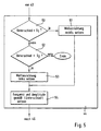
- step 48 for controlling the wheel brake of Figure 4b is explained in more detail.
- step 60 it is first queried in step 60 whether the difference is greater than a third threshold value S 3 . If this question is answered in the affirmative, the brake pressure for the right front wheel is increased in step 61. Thereafter, the process proceeds to step 64. If the query is answered in the negative in step 60, a query is made in step 62 as to whether the path difference is smaller than a fourth threshold value S 4 . If this query is answered in the negative, the procedure is ended. However, if the answer is in the affirmative, the brake pressure for the left front wheel is increased in step 63. Subsequently, in step 64, the brake pressure level is set according to the amount of difference of the comparison. Thereafter, the process is completed.
- a difference is interrogated in each case.
- This difference can be both the difference in movement and the path difference. Accordingly, then the thresholds S 1 to S 4 are to be selected.
- the threshold values should preferably also depend on the allowed deviation between z. B. Actual movement and target movement can be selected. So z. B. a slight deviation still be allowed, then z. B. requires no brake intervention.
- steps 51 and 53 of Figure 5 are to be understood that not directly a wave is set in motion, but initially only the direction is set and this accordingly passed on in step 54 together with the frequency and the amplitude as information to step 45 become. Only there is the implementation of this information.
- step 61 and 63 of Figure 6 are also to be seen so that initially only determines on which front wheel, the brake pressure is increased. Only in step 64, the brake pressure is then used at the corresponding wheel with the determined brake pressure level for braking.
- the information size can be determined via one or more fuzzy functions, and the wheel brake can be controlled as a function of one or more fuzzy functions.
- fuzzy function should mean both a fuzzification and a defuzzification.
- a fuzzy control seems sensible because z. B. the determination of the desired movement of the target path can lead to many results, since there are many ways to move the vehicle on the target path. So z. B. the Sollweg be traversed at different speeds. This decision is usually made by the driver, the z. B. can only determine the speed inaccurate. In the desired movement determination device 13 can therefore z. For example, an attempt may be made to map the possible activities of a driver who will lead the vehicle to the desired path. For this, fuzzy sets or functions (fuzzy functions) can advantageously be selected.
- the information-determining device 15 can determine an information quantity for transmission to the driver from the difference ascertained in the movement-difference determination device 14 via fuzzy functions.
- the exact size (amplitude) is not important, it needs z. B. only a steering tendency to be displayed because the driver can only tend to feel and not absolute.
- the extrapolation device 23 also only needs to determine the actual travel approximately from the actual movement, which is why fuzzy functions are also suitable here. Likewise, the control of the wheel brakes in the Radbremsenan Kunststoff 25 tend to happen, so that here also offers a determination of the brake pressures on fuzzy functions.
Landscapes
- Engineering & Computer Science (AREA)
- Transportation (AREA)
- Mechanical Engineering (AREA)
- Chemical & Material Sciences (AREA)
- Combustion & Propulsion (AREA)
- Physics & Mathematics (AREA)
- Software Systems (AREA)
- Theoretical Computer Science (AREA)
- Mathematical Physics (AREA)
- Fuzzy Systems (AREA)
- Regulating Braking Force (AREA)
- Steering Control In Accordance With Driving Conditions (AREA)
- Traffic Control Systems (AREA)
- Control Of Driving Devices And Active Controlling Of Vehicle (AREA)
Applications Claiming Priority (3)
| Application Number | Priority Date | Filing Date | Title |
|---|---|---|---|
| DE19916267 | 1999-04-12 | ||
| DE19916267A DE19916267A1 (de) | 1999-04-12 | 1999-04-12 | Verfahren und Vorrichtung zum Überwachen oder zum Beeinflussen der Bewegung eines Fahrzeugs auf einem Weg |
| PCT/EP2000/003007 WO2000061413A1 (de) | 1999-04-12 | 2000-04-05 | Verfahren und vorrichtung zum überwachen oder zum beeinflussen der bewegung eines fahrzeugs auf einem weg |
Publications (2)
| Publication Number | Publication Date |
|---|---|
| EP1171333A1 EP1171333A1 (de) | 2002-01-16 |
| EP1171333B1 true EP1171333B1 (de) | 2006-12-20 |
Family
ID=7904165
Family Applications (1)
| Application Number | Title | Priority Date | Filing Date |
|---|---|---|---|
| EP00917047A Expired - Lifetime EP1171333B1 (de) | 1999-04-12 | 2000-04-05 | Verfahren und vorrichtung zum überwachen oder zum beeinflussen der bewegung eines fahrzeugs auf einem weg |
Country Status (5)
| Country | Link |
|---|---|
| US (1) | US6622076B1 (https=) |
| EP (1) | EP1171333B1 (https=) |
| JP (1) | JP4695263B2 (https=) |
| DE (2) | DE19916267A1 (https=) |
| WO (1) | WO2000061413A1 (https=) |
Families Citing this family (36)
| Publication number | Priority date | Publication date | Assignee | Title |
|---|---|---|---|---|
| DE20101014U1 (de) * | 2001-01-19 | 2002-06-06 | ESG Elektroniksystem- und Logistik-GmbH, 81675 München | Warnvorrichtung in einem bodengebundenen Fahrzeug |
| DE60226817D1 (de) | 2001-08-23 | 2008-07-10 | Nissan Motor | Fahrassistenzsystem |
| DE10151015A1 (de) * | 2001-10-16 | 2003-04-17 | Volkswagen Ag | Verfahren und Vorrichtung zur Aufmerksamkeitskontrolle eines Kraftfahrzeugführers |
| JP3820984B2 (ja) * | 2001-12-26 | 2006-09-13 | 日産自動車株式会社 | 車線逸脱防止装置 |
| SE0200464D0 (sv) | 2002-02-18 | 2002-02-18 | Scania Cv Abp | Preventing system for a vehicle |
| JP3617501B2 (ja) * | 2002-03-18 | 2005-02-09 | 日産自動車株式会社 | 車両用減速補助装置 |
| DE10232295A1 (de) | 2002-07-16 | 2004-02-05 | Daimlerchrysler Ag | Verfahren zur Unterstützung des Fahrers bei Fahrmanövern |
| DE20212398U1 (de) * | 2002-08-12 | 2002-12-19 | TRW Automotive Safety Systems GmbH & Co. KG, 63743 Aschaffenburg | Fahrzeuglenkrad und Sicherheitssystem |
| GB2394702A (en) * | 2002-10-30 | 2004-05-05 | Trw Ltd | Video enhanced stability control in road vehicles |
| JP3661684B2 (ja) * | 2002-11-28 | 2005-06-15 | 日産自動車株式会社 | 車線逸脱防止装置 |
| DE10306704B3 (de) * | 2003-02-18 | 2004-10-07 | Robert Bosch Gmbh | Verfahren und Vorrichtung zur Erzeugung einer verkehrsangepassten Bremsdruckempfehlung |
| US7668633B2 (en) | 2003-03-26 | 2010-02-23 | Continental Tevas Ag & Co. Ohg | Electronic control system for a vehicle and method for determining at least one driver-independent intervention in a vehicle system |
| DE10322828B4 (de) * | 2003-05-19 | 2007-12-20 | Daimlerchrysler Ag | Steuerungssystem für ein Fahrzeug |
| JP2005112007A (ja) * | 2003-10-02 | 2005-04-28 | Toyoda Mach Works Ltd | 車両の統合制御装置 |
| JP2005112008A (ja) * | 2003-10-02 | 2005-04-28 | Toyoda Mach Works Ltd | 車両の統合制御装置 |
| US7197388B2 (en) * | 2003-11-06 | 2007-03-27 | Ford Global Technologies, Llc | Roll stability control system for an automotive vehicle using an external environmental sensing system |
| DE102004004336A1 (de) * | 2004-01-29 | 2005-08-18 | Zf Friedrichshafen Ag | Fahrstabilitätsregelungsverfahren für ein Kraftfahrzeug |
| DE102004023546A1 (de) * | 2004-05-13 | 2005-12-01 | Daimlerchrysler Ag | Verfahren zur Spurhaltung und Spurhaltesystem |
| DE102004058676A1 (de) * | 2004-12-06 | 2006-06-14 | Robert Bosch Gmbh | Spurhaltesystem für Kraftfahrzeuge mit Trajektorienbestimmung |
| JP2006264624A (ja) * | 2005-03-25 | 2006-10-05 | Daimler Chrysler Ag | 車線維持支援装置 |
| DE102005017242A1 (de) | 2005-04-14 | 2006-10-19 | Conti Temic Microelectronic Gmbh | Fahrerassistenzsystem zur Müdigkeitserkennung und/oder Aufmerksamkeitsbeurteilung eines Fahrzeugführers |
| DE102005029716B4 (de) * | 2005-06-24 | 2016-02-25 | Knorr-Bremse Systeme für Nutzfahrzeuge GmbH | Verfahren zur Erhöhung der Fahrstabilität eines Fahrzeugs |
| DE102005063343C5 (de) * | 2005-06-24 | 2019-07-11 | Knorr-Bremse Systeme für Nutzfahrzeuge GmbH | Verfahren zur Erhöhung der Fahrstabilität eines Fahrzeugs |
| US20070179697A1 (en) * | 2006-01-31 | 2007-08-02 | Bendix Commercial Vehicle Systems Llc | Lane departure warning system and method |
| US8068135B2 (en) * | 2007-07-06 | 2011-11-29 | Chol Kim | Device and method for detection and prevention of motor vehicle accidents |
| CN101778753B (zh) * | 2007-08-15 | 2012-12-05 | 沃尔沃技术公司 | 用于支持车辆的车道保持的操作方法和系统 |
| KR101338055B1 (ko) | 2007-12-13 | 2013-12-16 | 현대자동차주식회사 | 타이어 공기압을 고려한 차선유지 보조 시스템 |
| DE102008005310A1 (de) | 2008-01-21 | 2009-07-23 | Bayerische Motoren Werke Aktiengesellschaft | Verfahren zur Beeinflussung der Bewegung eines Fahrzeugs bei vorzeitigem Erkennen einer unvermeidbaren Kollision mit einem Hindernis |
| DE102008005305B4 (de) | 2008-01-21 | 2025-04-30 | Bayerische Motoren Werke Aktiengesellschaft | Verfahren zur Beeinflussung der Bewegung eines Fahrzeugs |
| DE102008064645A1 (de) * | 2008-04-11 | 2010-04-08 | Knorr-Bremse Systeme für Nutzfahrzeuge GmbH | Fahrerassistenzanlage für Kraftfahrzeuge und Verfahren zum haptischen Warnen eines Fahrers eines Kraftfahrzeuges |
| US20110221606A1 (en) * | 2010-03-11 | 2011-09-15 | Laser Technology , Inc. | System and method for detecting a moving object in an image zone |
| SE535335C2 (sv) * | 2010-04-13 | 2012-07-03 | Autoliv Dev | Vibrationsanordning för en fordonsratt |
| DE102011118090B4 (de) | 2011-11-10 | 2015-08-06 | Autoliv Development Ab | Lenkradeinheit |
| EP2746126B1 (en) | 2012-12-18 | 2019-04-10 | Honda Research Institute Europe GmbH | Driver assistance system |
| DE102015219698A1 (de) * | 2015-10-12 | 2017-04-13 | Bayerische Motoren Werke Aktiengesellschaft | Haptische Benutzerschnittstelle für ein Fahrzeug |
| CN105667515A (zh) * | 2016-03-02 | 2016-06-15 | 江苏大学 | 一种基于模糊理论的车道偏离预警方法 |
Family Cites Families (12)
| Publication number | Priority date | Publication date | Assignee | Title |
|---|---|---|---|---|
| FR2679357B1 (fr) * | 1991-07-19 | 1997-01-31 | Matra Sep Imagerie Inf | Dispositif embarque et procede de reperage et de suivi de la position d'un vehicule sur la route et dispositif d'aide a la conduite en comportant application. |
| DE4405379A1 (de) * | 1994-02-19 | 1995-08-24 | Bosch Gmbh Robert | Fahrdynamikregelsystem |
| JP3287117B2 (ja) * | 1994-07-05 | 2002-05-27 | 株式会社日立製作所 | 撮像装置を用いた車両用の環境認識装置 |
| DE19515050A1 (de) * | 1994-11-25 | 1996-05-30 | Teves Gmbh Alfred | Verfahren zur Fahrstabilitätsregelschaltung mit Steuerung über Druckgradienten |
| JP3523698B2 (ja) * | 1994-12-21 | 2004-04-26 | 光洋精工株式会社 | 電動パワーステアリング装置および予防安全装置 |
| JP3390289B2 (ja) * | 1995-06-16 | 2003-03-24 | 富士重工業株式会社 | 警報装置 |
| DE19528457C2 (de) * | 1995-08-03 | 2001-03-08 | Mannesmann Vdo Ag | Bedieneinrichtung |
| JPH09207801A (ja) * | 1996-02-08 | 1997-08-12 | Honda Motor Co Ltd | 車両用後方警戒装置 |
| JP3647538B2 (ja) * | 1996-02-12 | 2005-05-11 | 本田技研工業株式会社 | 車両操舵装置 |
| JP3223240B2 (ja) * | 1996-11-19 | 2001-10-29 | 本田技研工業株式会社 | 車両制御装置 |
| JP3235522B2 (ja) * | 1997-07-22 | 2001-12-04 | トヨタ自動車株式会社 | 走行レーン逸脱警報装置 |
| JP3468039B2 (ja) * | 1997-07-23 | 2003-11-17 | トヨタ自動車株式会社 | 車両用状態報知装置 |
-
1999
- 1999-04-12 DE DE19916267A patent/DE19916267A1/de not_active Ceased
-
2000
- 2000-04-05 JP JP2000610709A patent/JP4695263B2/ja not_active Expired - Lifetime
- 2000-04-05 EP EP00917047A patent/EP1171333B1/de not_active Expired - Lifetime
- 2000-04-05 WO PCT/EP2000/003007 patent/WO2000061413A1/de not_active Ceased
- 2000-04-05 DE DE50013887T patent/DE50013887D1/de not_active Expired - Lifetime
- 2000-04-05 US US09/937,758 patent/US6622076B1/en not_active Expired - Lifetime
Also Published As
| Publication number | Publication date |
|---|---|
| DE19916267A1 (de) | 2000-10-19 |
| JP2002541017A (ja) | 2002-12-03 |
| EP1171333A1 (de) | 2002-01-16 |
| WO2000061413A1 (de) | 2000-10-19 |
| JP4695263B2 (ja) | 2011-06-08 |
| DE50013887D1 (de) | 2007-02-01 |
| US6622076B1 (en) | 2003-09-16 |
Similar Documents
| Publication | Publication Date | Title |
|---|---|---|
| EP1171333B1 (de) | Verfahren und vorrichtung zum überwachen oder zum beeinflussen der bewegung eines fahrzeugs auf einem weg | |
| EP2862773B1 (de) | Kraftfahrzeug und Verfahren zur Steuerung eines Kraftahrzeugs | |
| DE102017216408A1 (de) | Adaptive Abstandswahl zur Effizienzoptimierung | |
| DE102013013747A1 (de) | Fahrassistenzsystem, Fahrzeug mit einem Fahrassistenzsystem und Verfahren zum Betrieb eines Fahrerassistenzsystems | |
| DE102012203187A1 (de) | Verfahren und Vorrichtung zur Prädiktion und Adaption von Bewegungstrajektorien von Kraftfahrzeugen | |
| EP4298001B1 (de) | Verfahren und fahrerassistenzsystem zum unterstützen eines kraftfahrzeugs beim durchführen einer kurvenfahrt | |
| DE102019116005A1 (de) | Vorrichtung und verfahren zur längsregelung beim automatischen spurwechsel in einem fahrunterstützten fahrzeug | |
| DE102018130243A1 (de) | Erweitertes Szenario für Autobahnassistenten | |
| EP2464992A1 (de) | Kollisionsüberwachung für ein kraftfahrzeug | |
| DE102007020280A1 (de) | Verfahren und Vorrichtung für die Steuerung eines Fahrerassistenzsystems | |
| EP3148855B1 (de) | Bestimmen eines kritischen fahrzeugzustands | |
| DE102018210454B4 (de) | Vorrichtung und ein Verfahren zur Überwachung der Aktivität eines Fahrers eines Fahrzeugs | |
| DE102010035718B4 (de) | Verfahren zum Betrieb eines Fahrerassistenzsystems und Kraftfahrzeug | |
| DE102008047499A1 (de) | Verfahren und Vorrichtung zur Ausgabe einer Verkehrssituation | |
| DE102021004191A1 (de) | Verfahren zur Erkennung einer Überholabsicht und/oder Vorhersage von Einschermanövern von Fahrzeugen vor einem Ego-Fahrzeug | |
| EP3177505B1 (de) | Bereitstellen von fahrhinweisen während eines parkmanövers | |
| DE102017200436B4 (de) | Verfahren zum Betrieb eines Fahrerassistenzsystems eines Kraftfahrzeugs | |
| EP3385138B1 (de) | Vorrichtung zur konfiguration eines fahrerassistenzsystems | |
| EP4429924B1 (de) | Verfahren und vorrichtung zur längsregelung eines fahrzeugs | |
| WO2019068891A1 (de) | Verfahren zum betreiben eines lenksystems und lenksystem | |
| DE102018002335A1 (de) | Steuerungssystem und Steuerungsverfahren zum vorausschauenden Begrenzen einer Fahrzeugbeschleunigung | |
| DE102023002351A1 (de) | Verfahren zur Durchführung einer prädiktiven Lenksteuerung sowie Steer-by-Wire-Lenksystem | |
| DE102017122426A1 (de) | Steuerung mit Vorgabe eines Geschwindigkeitsprofils | |
| DE102021003291A1 (de) | Verfahren zum Betrieb eines Fahrzeuges | |
| EP4552939A1 (de) | Verfahren zur längsführung eines fahrzeugs in bezug zu einem vorausfahrenden vorderfahrzeug mittels eines elektronischen abstandshaltesystems sowie ein abstandshaltesystem für ein fahrzeug |
Legal Events
| Date | Code | Title | Description |
|---|---|---|---|
| PUAI | Public reference made under article 153(3) epc to a published international application that has entered the european phase |
Free format text: ORIGINAL CODE: 0009012 |
|
| 17P | Request for examination filed |
Effective date: 20011112 |
|
| AK | Designated contracting states |
Kind code of ref document: A1 Designated state(s): AT BE CH CY DE DK ES FI FR GB GR IE IT LI LU MC NL PT SE |
|
| 17Q | First examination report despatched |
Effective date: 20021007 |
|
| RBV | Designated contracting states (corrected) |
Designated state(s): DE FR GB |
|
| GRAP | Despatch of communication of intention to grant a patent |
Free format text: ORIGINAL CODE: EPIDOSNIGR1 |
|
| GRAS | Grant fee paid |
Free format text: ORIGINAL CODE: EPIDOSNIGR3 |
|
| GRAA | (expected) grant |
Free format text: ORIGINAL CODE: 0009210 |
|
| AK | Designated contracting states |
Kind code of ref document: B1 Designated state(s): DE FR GB |
|
| REG | Reference to a national code |
Ref country code: GB Ref legal event code: FG4D Free format text: NOT ENGLISH |
|
| REF | Corresponds to: |
Ref document number: 50013887 Country of ref document: DE Date of ref document: 20070201 Kind code of ref document: P |
|
| PGFP | Annual fee paid to national office [announced via postgrant information from national office to epo] |
Ref country code: GB Payment date: 20070327 Year of fee payment: 8 |
|
| ET | Fr: translation filed | ||
| GBV | Gb: ep patent (uk) treated as always having been void in accordance with gb section 77(7)/1977 [no translation filed] |
Effective date: 20061220 |
|
| PLBE | No opposition filed within time limit |
Free format text: ORIGINAL CODE: 0009261 |
|
| STAA | Information on the status of an ep patent application or granted ep patent |
Free format text: STATUS: NO OPPOSITION FILED WITHIN TIME LIMIT |
|
| PG25 | Lapsed in a contracting state [announced via postgrant information from national office to epo] |
Ref country code: GB Free format text: LAPSE BECAUSE OF FAILURE TO SUBMIT A TRANSLATION OF THE DESCRIPTION OR TO PAY THE FEE WITHIN THE PRESCRIBED TIME-LIMIT Effective date: 20061220 |
|
| 26N | No opposition filed |
Effective date: 20070921 |
|
| PGFP | Annual fee paid to national office [announced via postgrant information from national office to epo] |
Ref country code: FR Payment date: 20140422 Year of fee payment: 15 |
|
| REG | Reference to a national code |
Ref country code: FR Ref legal event code: ST Effective date: 20151231 |
|
| PG25 | Lapsed in a contracting state [announced via postgrant information from national office to epo] |
Ref country code: FR Free format text: LAPSE BECAUSE OF NON-PAYMENT OF DUE FEES Effective date: 20150430 |
|
| PGFP | Annual fee paid to national office [announced via postgrant information from national office to epo] |
Ref country code: DE Payment date: 20190430 Year of fee payment: 20 |
|
| REG | Reference to a national code |
Ref country code: DE Ref legal event code: R071 Ref document number: 50013887 Country of ref document: DE |