EP1168593A2 - Appareil pour production d'énergie mécanique et onduleur - Google Patents
Appareil pour production d'énergie mécanique et onduleur Download PDFInfo
- Publication number
- EP1168593A2 EP1168593A2 EP01115029A EP01115029A EP1168593A2 EP 1168593 A2 EP1168593 A2 EP 1168593A2 EP 01115029 A EP01115029 A EP 01115029A EP 01115029 A EP01115029 A EP 01115029A EP 1168593 A2 EP1168593 A2 EP 1168593A2
- Authority
- EP
- European Patent Office
- Prior art keywords
- dynamo
- electric motor
- mechanical power
- pole bus
- inverter circuit
- Prior art date
- Legal status (The legal status is an assumption and is not a legal conclusion. Google has not performed a legal analysis and makes no representation as to the accuracy of the status listed.)
- Granted
Links
Images


Classifications
-
- B—PERFORMING OPERATIONS; TRANSPORTING
- B60—VEHICLES IN GENERAL
- B60K—ARRANGEMENT OR MOUNTING OF PROPULSION UNITS OR OF TRANSMISSIONS IN VEHICLES; ARRANGEMENT OR MOUNTING OF PLURAL DIVERSE PRIME-MOVERS IN VEHICLES; AUXILIARY DRIVES FOR VEHICLES; INSTRUMENTATION OR DASHBOARDS FOR VEHICLES; ARRANGEMENTS IN CONNECTION WITH COOLING, AIR INTAKE, GAS EXHAUST OR FUEL SUPPLY OF PROPULSION UNITS IN VEHICLES
- B60K6/00—Arrangement or mounting of plural diverse prime-movers for mutual or common propulsion, e.g. hybrid propulsion systems comprising electric motors and internal combustion engines ; Control systems therefor, i.e. systems controlling two or more prime movers, or controlling one of these prime movers and any of the transmission, drive or drive units Informative references: mechanical gearings with secondary electric drive F16H3/72; arrangements for handling mechanical energy structurally associated with the dynamo-electric machine H02K7/00; machines comprising structurally interrelated motor and generator parts H02K51/00; dynamo-electric machines not otherwise provided for in H02K see H02K99/00
- B60K6/20—Arrangement or mounting of plural diverse prime-movers for mutual or common propulsion, e.g. hybrid propulsion systems comprising electric motors and internal combustion engines ; Control systems therefor, i.e. systems controlling two or more prime movers, or controlling one of these prime movers and any of the transmission, drive or drive units Informative references: mechanical gearings with secondary electric drive F16H3/72; arrangements for handling mechanical energy structurally associated with the dynamo-electric machine H02K7/00; machines comprising structurally interrelated motor and generator parts H02K51/00; dynamo-electric machines not otherwise provided for in H02K see H02K99/00 the prime-movers consisting of electric motors and internal combustion engines, e.g. HEVs
- B60K6/22—Arrangement or mounting of plural diverse prime-movers for mutual or common propulsion, e.g. hybrid propulsion systems comprising electric motors and internal combustion engines ; Control systems therefor, i.e. systems controlling two or more prime movers, or controlling one of these prime movers and any of the transmission, drive or drive units Informative references: mechanical gearings with secondary electric drive F16H3/72; arrangements for handling mechanical energy structurally associated with the dynamo-electric machine H02K7/00; machines comprising structurally interrelated motor and generator parts H02K51/00; dynamo-electric machines not otherwise provided for in H02K see H02K99/00 the prime-movers consisting of electric motors and internal combustion engines, e.g. HEVs characterised by apparatus, components or means specially adapted for HEVs
- B60K6/36—Arrangement or mounting of plural diverse prime-movers for mutual or common propulsion, e.g. hybrid propulsion systems comprising electric motors and internal combustion engines ; Control systems therefor, i.e. systems controlling two or more prime movers, or controlling one of these prime movers and any of the transmission, drive or drive units Informative references: mechanical gearings with secondary electric drive F16H3/72; arrangements for handling mechanical energy structurally associated with the dynamo-electric machine H02K7/00; machines comprising structurally interrelated motor and generator parts H02K51/00; dynamo-electric machines not otherwise provided for in H02K see H02K99/00 the prime-movers consisting of electric motors and internal combustion engines, e.g. HEVs characterised by apparatus, components or means specially adapted for HEVs characterised by the transmission gearings
- B60K6/365—Arrangement or mounting of plural diverse prime-movers for mutual or common propulsion, e.g. hybrid propulsion systems comprising electric motors and internal combustion engines ; Control systems therefor, i.e. systems controlling two or more prime movers, or controlling one of these prime movers and any of the transmission, drive or drive units Informative references: mechanical gearings with secondary electric drive F16H3/72; arrangements for handling mechanical energy structurally associated with the dynamo-electric machine H02K7/00; machines comprising structurally interrelated motor and generator parts H02K51/00; dynamo-electric machines not otherwise provided for in H02K see H02K99/00 the prime-movers consisting of electric motors and internal combustion engines, e.g. HEVs characterised by apparatus, components or means specially adapted for HEVs characterised by the transmission gearings with the gears having orbital motion
-
- B—PERFORMING OPERATIONS; TRANSPORTING
- B60—VEHICLES IN GENERAL
- B60K—ARRANGEMENT OR MOUNTING OF PROPULSION UNITS OR OF TRANSMISSIONS IN VEHICLES; ARRANGEMENT OR MOUNTING OF PLURAL DIVERSE PRIME-MOVERS IN VEHICLES; AUXILIARY DRIVES FOR VEHICLES; INSTRUMENTATION OR DASHBOARDS FOR VEHICLES; ARRANGEMENTS IN CONNECTION WITH COOLING, AIR INTAKE, GAS EXHAUST OR FUEL SUPPLY OF PROPULSION UNITS IN VEHICLES
- B60K6/00—Arrangement or mounting of plural diverse prime-movers for mutual or common propulsion, e.g. hybrid propulsion systems comprising electric motors and internal combustion engines ; Control systems therefor, i.e. systems controlling two or more prime movers, or controlling one of these prime movers and any of the transmission, drive or drive units Informative references: mechanical gearings with secondary electric drive F16H3/72; arrangements for handling mechanical energy structurally associated with the dynamo-electric machine H02K7/00; machines comprising structurally interrelated motor and generator parts H02K51/00; dynamo-electric machines not otherwise provided for in H02K see H02K99/00
- B60K6/20—Arrangement or mounting of plural diverse prime-movers for mutual or common propulsion, e.g. hybrid propulsion systems comprising electric motors and internal combustion engines ; Control systems therefor, i.e. systems controlling two or more prime movers, or controlling one of these prime movers and any of the transmission, drive or drive units Informative references: mechanical gearings with secondary electric drive F16H3/72; arrangements for handling mechanical energy structurally associated with the dynamo-electric machine H02K7/00; machines comprising structurally interrelated motor and generator parts H02K51/00; dynamo-electric machines not otherwise provided for in H02K see H02K99/00 the prime-movers consisting of electric motors and internal combustion engines, e.g. HEVs
- B60K6/42—Arrangement or mounting of plural diverse prime-movers for mutual or common propulsion, e.g. hybrid propulsion systems comprising electric motors and internal combustion engines ; Control systems therefor, i.e. systems controlling two or more prime movers, or controlling one of these prime movers and any of the transmission, drive or drive units Informative references: mechanical gearings with secondary electric drive F16H3/72; arrangements for handling mechanical energy structurally associated with the dynamo-electric machine H02K7/00; machines comprising structurally interrelated motor and generator parts H02K51/00; dynamo-electric machines not otherwise provided for in H02K see H02K99/00 the prime-movers consisting of electric motors and internal combustion engines, e.g. HEVs characterised by the architecture of the hybrid electric vehicle
- B60K6/46—Series type
-
- B—PERFORMING OPERATIONS; TRANSPORTING
- B60—VEHICLES IN GENERAL
- B60L—PROPULSION OF ELECTRICALLY-PROPELLED VEHICLES; SUPPLYING ELECTRIC POWER FOR AUXILIARY EQUIPMENT OF ELECTRICALLY-PROPELLED VEHICLES; ELECTRODYNAMIC BRAKE SYSTEMS FOR VEHICLES IN GENERAL; MAGNETIC SUSPENSION OR LEVITATION FOR VEHICLES; MONITORING OPERATING VARIABLES OF ELECTRICALLY-PROPELLED VEHICLES; ELECTRIC SAFETY DEVICES FOR ELECTRICALLY-PROPELLED VEHICLES
- B60L15/00—Methods, circuits, or devices for controlling the traction-motor speed of electrically-propelled vehicles
- B60L15/02—Methods, circuits, or devices for controlling the traction-motor speed of electrically-propelled vehicles characterised by the form of the current used in the control circuit
- B60L15/025—Methods, circuits, or devices for controlling the traction-motor speed of electrically-propelled vehicles characterised by the form of the current used in the control circuit using field orientation; Vector control; Direct Torque Control [DTC]
-
- B—PERFORMING OPERATIONS; TRANSPORTING
- B60—VEHICLES IN GENERAL
- B60L—PROPULSION OF ELECTRICALLY-PROPELLED VEHICLES; SUPPLYING ELECTRIC POWER FOR AUXILIARY EQUIPMENT OF ELECTRICALLY-PROPELLED VEHICLES; ELECTRODYNAMIC BRAKE SYSTEMS FOR VEHICLES IN GENERAL; MAGNETIC SUSPENSION OR LEVITATION FOR VEHICLES; MONITORING OPERATING VARIABLES OF ELECTRICALLY-PROPELLED VEHICLES; ELECTRIC SAFETY DEVICES FOR ELECTRICALLY-PROPELLED VEHICLES
- B60L50/00—Electric propulsion with power supplied within the vehicle
- B60L50/10—Electric propulsion with power supplied within the vehicle using propulsion power supplied by engine-driven generators, e.g. generators driven by combustion engines
- B60L50/16—Electric propulsion with power supplied within the vehicle using propulsion power supplied by engine-driven generators, e.g. generators driven by combustion engines with provision for separate direct mechanical propulsion
-
- B—PERFORMING OPERATIONS; TRANSPORTING
- B60—VEHICLES IN GENERAL
- B60L—PROPULSION OF ELECTRICALLY-PROPELLED VEHICLES; SUPPLYING ELECTRIC POWER FOR AUXILIARY EQUIPMENT OF ELECTRICALLY-PROPELLED VEHICLES; ELECTRODYNAMIC BRAKE SYSTEMS FOR VEHICLES IN GENERAL; MAGNETIC SUSPENSION OR LEVITATION FOR VEHICLES; MONITORING OPERATING VARIABLES OF ELECTRICALLY-PROPELLED VEHICLES; ELECTRIC SAFETY DEVICES FOR ELECTRICALLY-PROPELLED VEHICLES
- B60L50/00—Electric propulsion with power supplied within the vehicle
- B60L50/50—Electric propulsion with power supplied within the vehicle using propulsion power supplied by batteries or fuel cells
- B60L50/60—Electric propulsion with power supplied within the vehicle using propulsion power supplied by batteries or fuel cells using power supplied by batteries
- B60L50/61—Electric propulsion with power supplied within the vehicle using propulsion power supplied by batteries or fuel cells using power supplied by batteries by batteries charged by engine-driven generators, e.g. series hybrid electric vehicles
-
- B—PERFORMING OPERATIONS; TRANSPORTING
- B60—VEHICLES IN GENERAL
- B60W—CONJOINT CONTROL OF VEHICLE SUB-UNITS OF DIFFERENT TYPE OR DIFFERENT FUNCTION; CONTROL SYSTEMS SPECIALLY ADAPTED FOR HYBRID VEHICLES; ROAD VEHICLE DRIVE CONTROL SYSTEMS FOR PURPOSES NOT RELATED TO THE CONTROL OF A PARTICULAR SUB-UNIT
- B60W10/00—Conjoint control of vehicle sub-units of different type or different function
- B60W10/04—Conjoint control of vehicle sub-units of different type or different function including control of propulsion units
- B60W10/08—Conjoint control of vehicle sub-units of different type or different function including control of propulsion units including control of electric propulsion units, e.g. motors or generators
-
- H—ELECTRICITY
- H02—GENERATION; CONVERSION OR DISTRIBUTION OF ELECTRIC POWER
- H02P—CONTROL OR REGULATION OF ELECTRIC MOTORS, ELECTRIC GENERATORS OR DYNAMO-ELECTRIC CONVERTERS; CONTROLLING TRANSFORMERS, REACTORS OR CHOKE COILS
- H02P27/00—Arrangements or methods for the control of AC motors characterised by the kind of supply voltage
- H02P27/04—Arrangements or methods for the control of AC motors characterised by the kind of supply voltage using variable-frequency supply voltage, e.g. inverter or converter supply voltage
- H02P27/06—Arrangements or methods for the control of AC motors characterised by the kind of supply voltage using variable-frequency supply voltage, e.g. inverter or converter supply voltage using dc to ac converters or inverters
- H02P27/08—Arrangements or methods for the control of AC motors characterised by the kind of supply voltage using variable-frequency supply voltage, e.g. inverter or converter supply voltage using dc to ac converters or inverters with pulse width modulation
-
- H—ELECTRICITY
- H02—GENERATION; CONVERSION OR DISTRIBUTION OF ELECTRIC POWER
- H02P—CONTROL OR REGULATION OF ELECTRIC MOTORS, ELECTRIC GENERATORS OR DYNAMO-ELECTRIC CONVERTERS; CONTROLLING TRANSFORMERS, REACTORS OR CHOKE COILS
- H02P6/00—Arrangements for controlling synchronous motors or other dynamo-electric motors using electronic commutation dependent on the rotor position; Electronic commutators therefor
- H02P6/08—Arrangements for controlling the speed or torque of a single motor
-
- B—PERFORMING OPERATIONS; TRANSPORTING
- B60—VEHICLES IN GENERAL
- B60K—ARRANGEMENT OR MOUNTING OF PROPULSION UNITS OR OF TRANSMISSIONS IN VEHICLES; ARRANGEMENT OR MOUNTING OF PLURAL DIVERSE PRIME-MOVERS IN VEHICLES; AUXILIARY DRIVES FOR VEHICLES; INSTRUMENTATION OR DASHBOARDS FOR VEHICLES; ARRANGEMENTS IN CONNECTION WITH COOLING, AIR INTAKE, GAS EXHAUST OR FUEL SUPPLY OF PROPULSION UNITS IN VEHICLES
- B60K1/00—Arrangement or mounting of electrical propulsion units
- B60K1/02—Arrangement or mounting of electrical propulsion units comprising more than one electric motor
-
- B—PERFORMING OPERATIONS; TRANSPORTING
- B60—VEHICLES IN GENERAL
- B60L—PROPULSION OF ELECTRICALLY-PROPELLED VEHICLES; SUPPLYING ELECTRIC POWER FOR AUXILIARY EQUIPMENT OF ELECTRICALLY-PROPELLED VEHICLES; ELECTRODYNAMIC BRAKE SYSTEMS FOR VEHICLES IN GENERAL; MAGNETIC SUSPENSION OR LEVITATION FOR VEHICLES; MONITORING OPERATING VARIABLES OF ELECTRICALLY-PROPELLED VEHICLES; ELECTRIC SAFETY DEVICES FOR ELECTRICALLY-PROPELLED VEHICLES
- B60L2220/00—Electrical machine types; Structures or applications thereof
- B60L2220/10—Electrical machine types
- B60L2220/14—Synchronous machines
-
- Y—GENERAL TAGGING OF NEW TECHNOLOGICAL DEVELOPMENTS; GENERAL TAGGING OF CROSS-SECTIONAL TECHNOLOGIES SPANNING OVER SEVERAL SECTIONS OF THE IPC; TECHNICAL SUBJECTS COVERED BY FORMER USPC CROSS-REFERENCE ART COLLECTIONS [XRACs] AND DIGESTS
- Y02—TECHNOLOGIES OR APPLICATIONS FOR MITIGATION OR ADAPTATION AGAINST CLIMATE CHANGE
- Y02T—CLIMATE CHANGE MITIGATION TECHNOLOGIES RELATED TO TRANSPORTATION
- Y02T10/00—Road transport of goods or passengers
- Y02T10/60—Other road transportation technologies with climate change mitigation effect
- Y02T10/62—Hybrid vehicles
-
- Y—GENERAL TAGGING OF NEW TECHNOLOGICAL DEVELOPMENTS; GENERAL TAGGING OF CROSS-SECTIONAL TECHNOLOGIES SPANNING OVER SEVERAL SECTIONS OF THE IPC; TECHNICAL SUBJECTS COVERED BY FORMER USPC CROSS-REFERENCE ART COLLECTIONS [XRACs] AND DIGESTS
- Y02—TECHNOLOGIES OR APPLICATIONS FOR MITIGATION OR ADAPTATION AGAINST CLIMATE CHANGE
- Y02T—CLIMATE CHANGE MITIGATION TECHNOLOGIES RELATED TO TRANSPORTATION
- Y02T10/00—Road transport of goods or passengers
- Y02T10/60—Other road transportation technologies with climate change mitigation effect
- Y02T10/64—Electric machine technologies in electromobility
-
- Y—GENERAL TAGGING OF NEW TECHNOLOGICAL DEVELOPMENTS; GENERAL TAGGING OF CROSS-SECTIONAL TECHNOLOGIES SPANNING OVER SEVERAL SECTIONS OF THE IPC; TECHNICAL SUBJECTS COVERED BY FORMER USPC CROSS-REFERENCE ART COLLECTIONS [XRACs] AND DIGESTS
- Y02—TECHNOLOGIES OR APPLICATIONS FOR MITIGATION OR ADAPTATION AGAINST CLIMATE CHANGE
- Y02T—CLIMATE CHANGE MITIGATION TECHNOLOGIES RELATED TO TRANSPORTATION
- Y02T10/00—Road transport of goods or passengers
- Y02T10/60—Other road transportation technologies with climate change mitigation effect
- Y02T10/70—Energy storage systems for electromobility, e.g. batteries
-
- Y—GENERAL TAGGING OF NEW TECHNOLOGICAL DEVELOPMENTS; GENERAL TAGGING OF CROSS-SECTIONAL TECHNOLOGIES SPANNING OVER SEVERAL SECTIONS OF THE IPC; TECHNICAL SUBJECTS COVERED BY FORMER USPC CROSS-REFERENCE ART COLLECTIONS [XRACs] AND DIGESTS
- Y02—TECHNOLOGIES OR APPLICATIONS FOR MITIGATION OR ADAPTATION AGAINST CLIMATE CHANGE
- Y02T—CLIMATE CHANGE MITIGATION TECHNOLOGIES RELATED TO TRANSPORTATION
- Y02T10/00—Road transport of goods or passengers
- Y02T10/60—Other road transportation technologies with climate change mitigation effect
- Y02T10/7072—Electromobility specific charging systems or methods for batteries, ultracapacitors, supercapacitors or double-layer capacitors
-
- Y—GENERAL TAGGING OF NEW TECHNOLOGICAL DEVELOPMENTS; GENERAL TAGGING OF CROSS-SECTIONAL TECHNOLOGIES SPANNING OVER SEVERAL SECTIONS OF THE IPC; TECHNICAL SUBJECTS COVERED BY FORMER USPC CROSS-REFERENCE ART COLLECTIONS [XRACs] AND DIGESTS
- Y10—TECHNICAL SUBJECTS COVERED BY FORMER USPC
- Y10S—TECHNICAL SUBJECTS COVERED BY FORMER USPC CROSS-REFERENCE ART COLLECTIONS [XRACs] AND DIGESTS
- Y10S903/00—Hybrid electric vehicles, HEVS
- Y10S903/902—Prime movers comprising electrical and internal combustion motors
- Y10S903/903—Prime movers comprising electrical and internal combustion motors having energy storing means, e.g. battery, capacitor
- Y10S903/904—Component specially adapted for hev
- Y10S903/909—Gearing
- Y10S903/91—Orbital, e.g. planetary gears
Definitions
- the present invention relates to a mechanical power outputting apparatus.
- the apparatus regards a circuit constituted of the coil of each phase of the dynamo-electric motor and a switching element of each phase of the inverter as a boosting chopper circuit that stores electric charge in the capacitor by boosting the voltage of the direct-current power supply. Besides, the apparatus regards the charged capacitor as the direct-current power supply for driving the dynamo-electric motor.
- the control of the driving of the dynamo-electric motor and the control of the charging to the capacitor are simultaneously performed by the switching actions of the switching elements of the inverter circuit that are performed at the time of the imposition of the three-phase alternating current on the dynamo-electric motor.
- an actually used direct-current power supply may be one supplying a lower voltage than a voltage necessary for driving the dynamo-electric motor, but the capacitor is required to have a high withstand voltage.
- the high withstand voltage capacitor is large in size and high in cost, and further that causes the increase of the size and the cost of the mechanical power outputting apparatus.
- the conventional mechanical power outputting apparatus can drive a single dynamo-electric motor with the direct-current power supply of a low voltage, but it is difficult for the conventional mechanical power outputting apparatus to drive a plurality of dynamo-electric motors separately with the direct-current power supply of the low voltage.
- the conventional mechanical power outputting apparatus has a probability of a large current pulsation being generated in the current that flows into or flows out from the neutral point of the dynamo-electric motor to increase the loss of the dynamo-electric motor.
- PWM pulse width modulation
- a so-called zero voltage vector output state arises in which each phase voltage is the same .
- the zero voltage vector is output, because the potential at the neutral point of the dynamo-electric motor is fixed by the direct-current power supply, a large current flows through a neutral point-connected line of the dynamo-electric motor. Because the zero voltage vector takes two states, i.e.
- the direction of the current flowing through the neutral point-connected line of the dynamo-electric motor differs depending on which state the zero voltage vector is based.
- the large current pulsation is generated on the neutral point-connected line of the dynamo-electric motor.
- An object of the present invention is to make a mechanical power outputting apparatus small in size and cheap in cost, and to improve the durability thereof and the stability thereof.
- an electric power supplying section as a direct-current power supply is connected with either the positive pole bus or the negative pole bus of an inverter circuit, and the electric power supplying section is also connected with the neutral point of a dynamo-electric motor, and a charging section capable of charging and discharging is connected with the other bus between the positive pole bus and the negative pole bus of the inverter circuit that is not connected with the electric power supplying section, and the charging section is also connected with the neutral point of the dynamo-electric motor.
- the electric power supplying section and the charging section connect the positive pole bus and the negative pole bus of the inverter circuit in series, and then it is possible to drive the dynamo-electric motor on the supposition that the electric power supplying section and the charging section are an integrated direct-current power supply.
- a circuit constituted of the coil of each phase of the dynamo-electric motor and a switching element of each phase of the inverter circuit can charge the charging section by the use of the electric power of the electric power supplying section by means of the switching operation of the switching element, and the charging of the charging section and the driving of the dynamo-electric motor can be performed simultaneously by synchronization of the switching operation with the switching operation at the time of the driving of the dynamo-electric motor.
- the withstand voltage of the charging section is a value that is a result of the subtraction of the voltage of the electric power supplying section from a voltage necessary for driving the dynamo-electric motor
- the withstand voltage of the charging section can be lower than the withstand voltage of a capacitor connected with the positive pole bus and the negative pole bus of the inverter circuit.
- the charging section can be realized to be small in size and cheap in cost, namely the mechanical power outputting apparatus can be realized to be small in size and cheap in cost, and further the durability and the stability of the mechanical power outputting apparatus can be improved because the charging section is made to have a low withstand voltage.
- a circuit constituted of the coil of each phase of a first dynamo-electric motor that performs the rotation thereof and the driving thereof by a polyphase alternating current and a switching element of each phase of a first inverter circuit can be regarded as a circuit that boosts the voltage of a first electric power supplying section by means of the electric power of the electric power supplying section to store charge in a charging section, and further the charging section can be regarded as a direct-current power supply capable of driving the first dynamo-electric motor and a second dynamo-electric motor.
- the circuit constituted of the coil of each phase of the first dynamo-electric motor and the switching element of each phase of the first inverter circuit can charge the charging section by the use of the electric power of the first electric power supplying section by means of the switching operation of the switching elements of the first inverter circuit, and the charging of the charging section and the driving of the first dynamo-electric motor can be performed simultaneously by synchronization of the switching operation with the switching operation at the time of the driving of the first dynamo-electric motor. Still further, the second dynamo-electric motor can be driven to rotate by the switching operation of the switching elements of the second inverter circuit by means of the electric power stored in the charging section.
- the switching operation of the first inverter circuit and the switching operation of the second inverter circuit can be performed separately, the first dynamo-electric motor and the second dynamo-electric motor can be driven separately. That is, a plurality of dynamo-electric motors can separately be driven by the use of the electric power supplying section of a low voltage.
- a driving current is made to be a pseudo-polyphase alternating current of voltage levels of three steps or more, i.e. voltage levels of a positive voltage, a negative voltage, and an intermediate voltage in between these two, and consequently the probability of the appearance of the zero voltage vector where the voltage of each of the phases are the same voltage, but different from the voltage of a second power supply, can be largely decreased, and the probability of the appearance of current pulsations that can be generated at the neutral point of a dynamo-electric motor can be decreased. As a result, the loss of the dynamo-electric motor can be suppressed.
- a driving current is made to be a pseudo-polyphase alternating current of voltage levels of three steps or more, and consequently the probability of the appearance of the zero voltage vector, the voltage of each phase of which is the same voltage but different from the voltage of a second power supply, can be largely decreased, and the probability of the appearance of current pulsations that can be generated at the neutral point of a dynamo-electric motor can be decreased. As a result, the loss of the dynamo-electric motor can be suppressed.
- the switching of a plurality of switching elements in an inverter circuit is controlled on the basis of the modulated wave of each phase based on the voltage command of each phase of a polyphase alternating current and on the basis of the carrier wave of each phase having a prescribed phase difference between each other corresponding to each phase of the polyphase alternating current, and consequently the probability of the appearance of the zero voltage vector, the voltage of each phase of which is exactly the same voltage but different from the voltage of a second power supply, can be largely decreased , and the probability of the appearance of current pulsations that can be generated at the neutral point of a dynamo-electric motor can be decreased. As a result, the loss of the dynamo-electric motor can be suppressed.
- the switching of a plurality of switching elements in an inverter circuit is controlled on the basis of the modulated wave of each phase based on the voltage command of each phase of a polyphase alternating current and on the basis of the carrier wave of each phase having a prescribed phase difference between each other corresponding to each phase of the polyphase alternating current, and consequently the probability of the appearance of the zero voltage vector the voltage of each phase of which is the same voltage can be decreased , and the probability of the appearance of current pulsations that can be generated at the neutral point of a dynamo-electric motor can be decreased. As a result, the loss of the dynamo-electric motor can be suppressed.
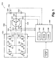
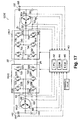
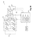
- Fig. 1 is the schematic diagram showing the configuration of the mechanical power outputting apparatus 520 that is the embodiment 1 of the present invention.
- the mechanical power outputting apparatus 520 of the embodiment 1 comprises, as shown in Fig.
- the motor 522 driven to rotate by a three-phase alternating current
- the inverter circuit 524 capable of converting direct-current power into three-phase alternating-current power for supply to the motor 522
- a direct-current power supply 530 connected between the negative pole bus 528 of the inverter circuit 524 and the neutral point of the motor 522
- a capacitor 532 connected between the positive pole bus 526 of the inverter circuit 524 and the neutral point of the motor 522
- the electronic control unit 540 for controlling the whole apparatus.
- the motor 522 is composed as a synchronous generation dynamo-electric motor capable of generating electrical energy, which is composed of, for example, a rotor having a permanent magnet affixed on the outer surface and a stator on which three-phase coils are wound.
- the rotating shaft of the motor 522 is set as the output shaft of the mechanical power outputting apparatus 520 of the embodiment 1, and mechanical power is output from the rotating shaft.
- the motor 522 of the embodiment 1 is composed as a generating dynamo-electric motor, if mechanical power is input into the rotating shaft of the motor 522, it is possible to generate electrical energy with the motor 522.
- the inverter circuit 524 is composed of six transistors T1-T6 and six diodes D1-D6.
- the six transistors T1-T6 are disposed in three pairs of two between the positive pole bus 526 and the negative pole bus 528 so that one of the paired transistors is on the source side and the other of them is on the sink side, respectively, and each of the three-phase coils (u, v and w) of the motor 522 is connected with each of the connection points of the pairs.
- the three-phase coils of the motor 522 form a rotating magnetic field that can drive the motor 522 to rotate.
- the electronic control unit 540 is composed as a microprocessor centering on a central processing unit (CPU) 542, and the electronic control unit 540 comprises a read only memory (ROM) 544 that stores a processing program, a random access memory (RAM) 546 that stores data temporarily and an input/output port (not shown).
- ROM read only memory
- RAM random access memory
- the electronic control unit 540 there are input through the input port the current of each phase from current sensors 552, 554 and 556 attached to each phase of the three-phase coils (u, v and w) of the motor 522, the neutral point current from a current sensor 558 attached to the neutral point of the motor 522, the rotation angle of the rotor of the motor 522 from a rotation angle sensor 560 attached to the rotating shaft of the motor 522, the voltage Vc between terminals of the capacitor 532 from a voltage sensor 562 attached to the capacitor 532, command values concerning the action of the motor 522, and the like.
- any one of the current sensors 552, 554, 556 and 558 can be omitted, and any one of them may be used as a sensor for abnormal detection use only.
- the electronic control unit 540 there are output, through the output port, control signals for performing the switching control of the transistors T1-T6 of the inverter circuit 524, and the like.
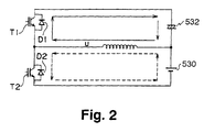
- Fig. 2 is the circuit diagram of a part of the mechanical power outputting apparatus 520 of the embodiment 1 when the leakage inductances of the three-phase coils of the motor 522 are featured.
- a state in which the transistor T2 is turned on is considered, a short circuit shown by the broken arrows in the figure is formed, and the u-phase of the three-phase coils of the motor 522 functions as a reactor.
- the transistor T2 is turned off, the energy that is stored in the u-phase of the three-phase coils that functions as a reactor is stored in the capacitor 532 through the charging circuit shown by the solid arrows in the figure.
- the circuit can be regarded as a chopper circuit for storing the energy of the direct-current power supply 530 in the capacitor 532. Because the v-phase and the w-phase of the three-phase coils of the motor 522 can also be regarded as a chopper circuit like the u-phase thereof, the capacitor 532 can be charged by the execution of the turning on and off of the transistors T2, T4 and T6.
- the potential difference is generated between the terminals of the capacitor 532, and the potential difference can be controlled by the adjustment of the quantity of the charge stored in the capacitor 532, i.e. the current flowing through the reactors. Consequently, the voltage Vc between the terminals of the capacitor 532 can also be made to be equal to the supply voltage Vb of the direct-current power supply 530. If the voltage Vc between the terminals of the capacitor 532 is thus made to be equal to the supply voltage Vb of the direct-current power supply 530, the mechanical power outputting apparatus 520 shown in Fig.
- a direct-current component can also be added to the three-phase alternating current. That is, the electrical potential of the pseudo-three-phase alternating current is offset to the plus side or to the minus side. If the three-phase alternating current including the direct-current component is supplied to the motor 522, the motor 522 can be driven to rotate by the alternating-current component, and the capacitor 532 can be charged by the direct-current component as described by the use of Fig. 2. That is, it is possible to charge the capacitor 532 at the same time as driving the motor 522. The voltage Vc between the terminals of the capacitor 532 can be controlled by the adjustment of the magnitude of the direct current component in this case.
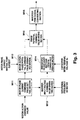
- FIG. 3 is the explanatory view for illustrating an example of the operation blocks when a control signal output to the inverter circuit 524 by the electronic control unit 540 of the mechanical power outputting apparatus 520 of the embodiment 1 is operated.
- the operation blocks are constituted of a motor phase current command value setting section M11 for setting a phase current command value of the motor 522 on the basis of an input motor action command value, a motor action phase potential command value operating section M12 for operating a phase potential command value for the action of the motor 522 (the phase potential command value of the alternating-current component) on the basis of each phase current of the motor 522 from the current sensors 552, 554 and 556, a neutral point current from the current sensor 558, and a motor phase current command value, an inverter input voltage command value operating section M13 for operating an inverter input voltage command value as a voltage command value between the positive pole bus 526 and the negative pole bus 528 of the inverter circuit 524 on the basis of the rotational frequency of the rotor of the motor 522 obtained on the basis of the rotation angle from the rotation angle sensor 560 and the motor phase current command value, an inverter input voltage adjustment phase potential command value operating section M14 for setting a phase potential command value for adjusting an invert
- the voltage Vc between the terminals of the capacitor 532 can be controlled and the driving control of the motor 522 can be performed by the switching control of the transistors T1-T6 of the inverter circuit 524.
- the supply voltage Vb of the direct-current power supply 530 can be made to be lower than a voltage necessary to drive the motor 522.
- the mechanical power outputting apparatus 520 of the embodiment 1 the following advantages are obtained in comparison with the conventional mechanical power outputting apparatus equipped with a capacitor connected between the positive pole bus 526 and the negative pole bus 528 of the inverter circuit 524.
- the mechanical power outputting apparatus 520 of the embodiment 1 because, in the mechanical power outputting apparatus 520 of the embodiment 1, the capacitor 532 is connected between the positive pole bus bar 526 of the inverter circuit 524 and the neutral point of the motor 522, the withstand voltage of the capacitor 532 can be smaller than that of the conventional mechanical power outputting apparatus. Moreover, the mechanical power outputting apparatus 520 of the embodiment 1 has an advantage that the initial charging at the time of starting the system that is necessary for the conventional mechanical power outputting apparatus is unnecessary. The conventional mechanical power outputting apparatus often separates the direct current power supply thereof from the system completely, for the purpose of ensuring safety and so forth at the time of the non-use of the system.
- the starting of the system is required to be performed to have a first step of performing the initial charging of the capacitor with a limiting resistor and a second step of performing the connection of the direct-current power supply with the system. Consequently, the conventional mechanical power outputting apparatus needs the limiting resistor and a relay.
- the mechanical power outputting apparatus 520 of the embodiment 1 can improve its features to be small in size, cheap in cost, excellent in durability, superior in stability, rapid in starting, and the like in comparison with the conventional mechanical power outputting apparatus.
- the direct-current power supply 530 is connected between the negative pole bus 528 of the inverter circuit 524 and the neutral point of the motor 522 and the capacitor 532 is connected between the positive pole bus 526 of the inverter circuit 524 and the neutral point of the motor 522
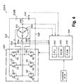
- a direct-current power supply 530B may be connected between the positive pole bus 526 of the inverter circuit 524 and the neutral point of the motor 522 and a capacitor 532B may be connected between the negative pole bus 528 of the inverter circuit 524 and the neutral point of the motor 522, like the modified mechanical power outputting apparatus 520B shown in Fig. 4.
- the modified mechanical power outputting apparatus 520B can also control the voltage Vc between the terminals of the capacitor 532B and can perform the driving control of the motor 522 by the switching control of the transistors T1-T6.
- the positive pole bus 526 and the negative pole bus 528 of the inverter circuit 524 are connected in series with the direct-current power supply 530 or 530B and the capacitor 532 or 532B
- a capacitor 564 connecting the positive pole bus 526 and the negative pole bus 528 may be provided as the modified mechanical power outputting apparatus 520C shown in Fig. 5.
- the capacitor 564 is used as a capacitor for the surge absorption of the transistors T1-T6, the capacitance thereof may be very small, but if it is used as a capacitor for storing energy, like the capacitors 532 and 532B, the capacitance thereof becomes large.
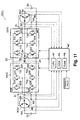
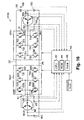
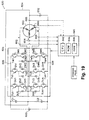
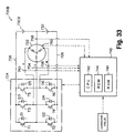
- Fig. 6 is a schematic diagram showing the outline of the configuration of the mechanical power outputting apparatus 20 that is the embodiment 2 of the present invention.
- the mechanical power outputting apparatus 20 of the embodiment 2 comprises, as shown in the figure, a motor MG1 driven to rotate by a three-phase alternating current, an inverter circuit INV1 capable of converting direct-current power into three-phase alternating-current power for supply to the motor MG1, a motor MG2 driven to rotate by a three-phase alternating current, an inverter circuit INV2 capable of converting direct-current power into three-phase alternating-current power for supply to the motor MG2, a direct-current power supply 30 connected between a negative pole bus 24 of the inverter circuit INV1 and the inverter circuit INV2 and the neutral point of the motor MG1, a capacitor 32 connected between a positive pole bus 22 of the inverter circuit INV1 and the inverter circuit INV2 and the negative pole bus 24, and an electronic control unit 40 to control the whole apparatus.
- Both of the motors MG1 and MG2 are composed as a synchronous generation dynamo-electric motor that is capable of generating electrical energy and is constituted of, for example, a rotor having a permanent magnet affixed on the outer surface and a stator on which three-phase coils are wound.
- the rotating shaft of the motor MG1 is set as the outputting shaft of the mechanical power outputting apparatus 20 of the embodiment 2, and mechanical power is output from the rotating shaft.
- the rotating shaft of the motor MG2 is indirectly connected with the outputting shaft of the mechanical power outputting apparatus 20 of the embodiment 2, and the mechanical power from the motor MG2 can also be indirectly output to the outputting shaft of the mechanical power outputting apparatus 20.
- the motors MG1 and MG2 of the embodiment 2 are composed as a generating dynamo-electric motor, if mechanical power is input into the rotating shafts of the motors MG1 and MG2, it is possible to generate electrical energy with the motors MG1 and MG2.
- Both of the inverter circuits INV1 and INV2 are composed of six transistors T11-T16 and T21-T26 and six diodes D11-D16 and D21-D26.
- the six transistors T11-T16 and T21-T26 are arranged as three pairs of two between the positive pole bus 22 and the negative pole bus 24 so that one of the paired transistors is on the source side and the other of them is on the sink side, respectively, and each of the three-phase coils (u, v and w) of the motors MG1 and MG2 is connected with each of the connection points of the pairs.
- the three-phase coils of the motors MG1 and MG2 form a rotating magnetic field that can drive the motors MG1 and MG2 to rotate. Because the switching control of the transistors T11-T16 of the inverter circuit INV1 and the switching control of the transistors T21-T26 of the inverter circuit INV2 can be performed independently, the driving control of the motors MG1 and MG2 can be performed independently.
- the electronic control unit 40 is composed as a microprocessor centering on a CPU 42, and the electronic control unit 40 comprises a ROM 44 that stores a processing program, a RAM 46 that stores data temporarily and an input/output port (not shown).
- the electronic control unit 40 there are input, through the input port, the current of each phase from current sensors 51-53 and 61-63 attached to each phase of the three-phase coils (u, v and w) of the motors MG1 and MG2, the neutral point current from a current sensor 54 attached to the neutral point of the motor MG1, the rotation angles of the rotors of the motors MG1 and MG2 from rotation angle sensors 56 and 66 attached to the respective rotating shafts of the motors MG1 and MG2, the voltage Vc between terminals of the capacitor 32 from a voltage sensor 68 attached to the capacitor 32, command values concerning the actions of the motors MG1 and MG2, and the like.
- control signals from the electronic control unit 40, there are output, through the output port, control
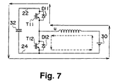
- Fig. 7 is a circuit diagram of a part of the mechanical power outputting apparatus 20 of the embodiment 2 when the u-phase of the three-phase coils of the motor MG1 is noticed.
- a state in which the transistor T12 of the u-phase of the inverter circuit INV1 is turned on is considered, a short circuit shown by the broken arrows in the figure is formed, and the u-phase of the three-phase coils of the motor MG1 functions as a reactor.
- the transistor T12 is turned off, the energy that is stored in the u-phase of the three-phase coils that functions as a reactor is stored in the capacitor 32 through the charging circuit shown by the solid arrows in the figure.
- the charged voltage in this case becomes higher than the supply voltage of the direct-current power supply 30.
- the direct-current power supply 30 can also be charged by means of the electrical potential of the capacitor 32 in the circuit. Consequently, the circuit can be regarded as a step-up and step-down chopper circuit that steps up the energy of the direct-current power supply 30 to store it in the capacitor 32 and can charge the direct-current power supply 30 by means of the electrical potential of the capacitor 32.
- the capacitor 32 can be charged by the execution of the turning on and off of the transistors T12, T14 and T16, and the direct-current power supply 30 can be charged by means of the electrical potential of the capacitor 32.
- the mechanical power outputting apparatus 20 shown in the Fig. 6 is in a state where a voltage that is twice as large as the supply voltage Vb of the direct-current power supply 30 and is generated by the capacitor 32 acts on the positive pole bus 22 and the negative pole bus 24.
- the motors MG1 and MG2 can be independently driven in conformity with the switching control of the transistors T11-T16 and T21-T26 of the inverter circuits INV1 and INV2.
- a direct-current component can also be added to the three-phase alternating current. That is, the electrical potential of the pseudo-three-phase alternating current is offset to the plus side or to the minus side. If the three-phase alternating current including the direct-current component is supplied to the motor MG1, the motor MG1 can be driven to rotate by the alternating-current component, and the capacitor 32 can be charged by the direct-current component as described by the use of the Fig. 7. That is, it is possible to charge the capacitor 32 at the same time to drive the motor MG1.
- the voltage Vc between the terminals of the capacitor 32 can be controlled by the adjustment of the largeness of the direct current component in this case.
- FIG. 8 is an explanatory view for illustrating an example of the operation blocks when a control signal output to the inverter circuits INV1 and INV2 by the electronic control unit 40 of the mechanical power outputting apparatus 20 of the embodiment 2 is operated.
- the operation blocks are constituted of a motor MG1 phase current command value setting section M1 for setting a phase current command value of the motor MG1 on the basis of an input action command value of the motor MG1, a motor MG1 action phase potential command value operating section M2 for operating a phase potential command value for the action of the motor MG1 (the phase potential command value of the alternating-current component) on the basis of each phase current of the motor MG1 from the current sensors 51-53, a neutral point current from the current sensor 54, and a motor phase current command value, a motor MG2 phase current command value setting section N1 for setting a phase current command value of the motor MG2 on the basis of an input action command value of the motor MG2, a motor MG2 action phase potential command value operating section N2 for operating a phase potential command value for the action of the motor MG2 on the basis of each phase current of the motor MG2 from the current sensors 61-63 and the phase current command value of the motor MG2, an inverter
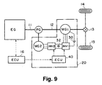
- Fig. 9 is a schematic diagram showing the outline of the configuration when the mechanical power outputting apparatus 20 of the embodiment 2 is applied as a part of the mechanical power outputting apparatus 10 of a vehicle.
- the mechanical power outputting apparatus 10 for a vehicle comprises an engine EG as an internal combustion engine, a planetary gear PG connected with the crank shaft 11 of the engine EG in a state of carrier connection, the mechanical power outputting apparatus 20 of the embodiment 2 that connects the motor MG2 with the rotating shaft connected with the sun gear of the planetary gear PG and connects the motor MG1 with the driving shaft 12 connected with the ring gear of the planetary gear PG, and an electronic control unit 16 for controlling the whole of the mechanical power outputting apparatus 10 for a vehicle.
- the drive shaft 12 is connected with drive wheels 14 and 15 through a differential gear 13, and the mechanical power output to the driving shaft 12 is finally output to the driving wheels 14 and 15.
- the mechanical power outputting apparatus 20 of the embodiment 2 can directly output mechanical power to the driving shaft 12 by the motor MG2 by means of the electric power from the direct-current power supply 30, the mechanical power outputting apparatus 20 can output the mechanical power to the driving shaft 12 by performing the torque conversion of the mechanical power output from the engine EG with the planetary gear PG. That is, the engine EG is driven at a driving point having a good efficiency, and the rotational frequency and the torque of the engine EG are converted into the rotational frequency and the torque of the driving shaft 12, respectively, to output the converted rotational frequency and the torque to the driving shaft 12.
- the motors MG1 and MG2 perform their driving as a dynamo-electric motor or as an electric generator as occasion demands.
- the capacitor 32 is charged by a motor that also functions as the electric generator, and the voltage Vc between the terminals thereof can be controlled by the exchange of energy between the capacitor 32 and the direct-current power supply 30.
- the direct-current power supply 30 can be charged by the use of a part of the mechanical power from the engine EG, and mechanical power can be added to the driving shaft 12 by the use of electric power from the direct-current power supply 30 together with the torque conversion of the mechanical power from the engine EG.
- braking force is made to operate on the driving wheels 14 and 15, it is also possible to charge the direct-current power supply 30 by the electric power obtained by the regenerative control of the motor MG1.
- the voltage Vc between the terminals of the capacitor 32 can be controlled and the driving control of the motor MG1 can be performed by the switching control of the transistors T11-T16 of the inverter circuit INV1.
- the driving control of the motor MG2 can be performed independently of the motor MG1 by the switching control of the transistors T21-T26 of the inverter circuit INV2.
- the supply voltage Vb of the direct-current power supply 30 can be made lower than a voltage necessary to drive the motor 22. Because the voltage Vc between the terminals of the capacitor 32 can be controlled, the voltage Vc can be set to a more suitable value according to the driving of the motors MG1 and MG2. As a result, the energy efficiency of the apparatus can be improved.
- the direct-current power supply 30 is connected between the negative pole bus 24 of the inverter circuits INV1 and INV2 and the neutral point of the motor MG1
- a direct-current power supply 30B may be connected between the positive pole bus 22 of the inverter circuits INV1 and INV2 and the neutral point of the motor MG1 like the modified mechanical power outputting apparatus 20B shown in Fig. 10.
- the modified mechanical power outputting apparatus 20B can also control the voltage Vc between the terminals of the capacitor 32 and can perform the driving control of the motor MG1 by the switching control of the transistors T11-T16.
- a direct-current power supply 70 may be connected between the negative pole bus 24 of the inverter circuits INV1 and INV2 and the neutral point of the motor MG2 in addition to the configuration of the mechanical power outputting apparatus 20 of the embodiment 2 like the modified mechanical power outputting apparatus 20C shown in Fig. 11.
- the voltage Vc between the terminals of the capacitor 32 can be controlled and the driving control of the motor MG2 can be performed by the switching control of the transistors T21-T26 of the inverter circuits INV2 in the modified mechanical power outputting apparatus 20C.
- the modified mechanical power outputting apparatus 20C can charge the capacitor 32 by means of both of the switching control of the transistors T11-T16 of the inverter circuit INV1 and the switching control of the transistors T21-T26 of the inverter circuit INV2.
- the direct-current power supply 30 may be attached so as to connect the positive pole bus 22 with the neutral point of the motor MG1
- either or both of the direct-current power supply 30 and the direct-current power supply 70 may be attached so as to connect the positive pole bus 22 with the neutral point of a corresponding motor.
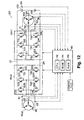
- Fig. 12 is the schematic diagram showing the outline of the configuration of the mechanical power outputting apparatus 120 of the embodiment 3.
- the mechanical power outputting apparatus 120 of the embodiment 3 has the same configuration as that of the mechanical power outputting apparatus of the embodiment 2 other than the disposition of a capacitor 132 as shown in the figure. Accordingly the same constitutional elements of the mechanical power outputting apparatus 120 of the embodiment 3 as those of the mechanical power outputting apparatus 20 of the embodiment 2 are designated by the same reference characters as those of the embodiment 2, and their descriptions are omitted.
- the capacitor 132 is attached so as to connect the positive pole bus 22 of the inverter circuits INV1 and INV2 with the neutral point of the motor MG1.
- Fig. 13 is a circuit diagram of a part of the mechanical power outputting apparatus 120 of the embodiment 3 when the u-phase of the three-phase coils of the motor MG1 is noticed.
- a state in which the transistor T12 of the u-phase of the inverter circuit INV1 is turned on is considered, a short circuit shown by the broken arrows in the figure is formed, and the u-phase of the three-phase coils of the motor MG1 functions as a reactor.
- the transistor T12 is turned off, the energy that is stored in the u-phase of the three-phase coils that functions as a reactor is stored in the capacitor 132 through the charging circuit shown by the solid arrows in the figure.
- the direct-current power supply 130 can also be charged by means of the electrical potential of the capacitor 132 similarly by the turning off of the transistor T11
- the circuit can be regarded as a chopper circuit that stores the energy of the direct-current power supply 130 in the capacitor 132 and can charge the direct-current power supply 130 by means of the electrical potential of the capacitor 132. Because the v-phase and the w-phase of the three-phase coils of the motor MG1 can also be regarded as a chopper circuit like the u-phase, the capacitor 132 can be charged by turning on and off of the transistors T11-T16, and the direct-current power supply 130 can be charged by means of the electrical potential of the capacitor 132.
- the potential difference is generated between the terminals of the capacitor 132, and the potential difference can be controlled by adjustment of the quantity of the charge stored in the capacitor 132, i.e. the current flowing through the reactor. Consequently, the voltage Vc between the terminals of the capacitor 132 can also be made to be equal to the supply voltage Vb of the direct-current power supply 130. If the voltage Vc between the terminals of the capacitor 132 is thus made to be equal to the supply voltage Vb of the direct-current power supply 130, the mechanical power outputting apparatus 120 shown in the Fig.
- the motors MG1 and MG2 can be independently driven in conformity with the switching control of the transistors T11-T16 and T21-T26 of the inverter circuits INV1 and INV2.
- a pseudo-three-phase alternating current generated by the switching control of the transistors T11-T16 constituting the inverter circuit INV1 should include a direct-current component
- the electrical potential of the pseudo-three-phase alternating current should be offset to the plus side or to the minus side. Consequently, the mechanical power outputting apparatus 120 of the embodiment 3 can also perform the switching control of the transistors T11-T16 and T21-T26 of the inverter circuits INV1 and INV2 by means of the operation blocks shown in Fig. 8.
- the same advantages as those of the mechanical power outputting apparatus 20 of the embodiment 2 can be obtained, namely the advantage that the control of the voltage Vc between the terminals of the capacitor 132 and the driving control of the motor MG1 can be performed simultaneously by the switching control of the inverter circuit INV1, an advantage that the driving control of the motor MG2 can be performed independently of the motor MG1 by the switching control of the inverter circuit INV2, and the like can be obtained.
- the mechanical power outputting apparatus 120 of the embodiment 3 makes the positive pole bus 22 and the negative pole bus 24 be in a state of being connected with a direct-current power supply composed of the capacitor 132 and the direct-current power supply 130, the withstand voltage of the capacitor 132 can be made smaller than the withstand voltage of the capacitor 32 of the embodiment 2.
- the mechanical power outputting apparatus 120 of the embodiment 3 can be smaller in size and cheaper in cost, and can improve its durability and stability.
- the mechanical power outputting apparatus 120 of the embodiment 3 can also be applied to a part of the mechanical power outputting apparatus for a vehicle shown in Fig. 9 similarly to the mechanical power outputting apparatus 20 of the embodiment 2.
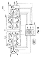
- a modified mechanical power outputting apparatus 120B shown in Fig. 14 may be structured so as to connect the positive pole bus 22 and the neutral point of the motor MG1 with a direct-current power supply 130B and connect the negative pole bus 24 and the neutral point of the motor MG1 with a capacitor 132B.
- the modified mechanical power outputting apparatus 120B can also control the voltage Vc between the terminals of a capacitor 132B and can perform the driving control of the motor MG1 by the switching control of the transistors T11-T16.
- a capacitor 170 connecting the positive pole bus 26 and the negative pole bus 28 may be provided like the modified mechanical power outputting apparatus 120C shown in Fig. 15.
- the surge absorption of the transistors T11-T16 of the inverter circuit INV1 and the transistors T21-T26 of the inverter circuit INV2 can be performed rapidly.
- the capacitor 170 is used as the surge absorption of the transistors T11-T16 and T21-T26, the capacitance thereof may be very small. However, if the capacitor 170 is used for storing energy like the capacitor 132, the capacitance thereof becomes large.
- a direct-current power supply 140 may be connected between the negative pole bus 24 of the inverter circuits INV1 and INV2 and the neutral point of the motor MG2 in addition to the configuration of the mechanical power outputting apparatus 120 of the embodiment 3, like the modified mechanical power outputting apparatus 120D shown in Fig. 16.
- the modified mechanical power outputting apparatus 120D can control the voltage Vc between the terminals of the capacitor 132 and can perform the driving control of the motor MG2 by the switching control of the transistors T21-T26 of the inverter circuit INV2. That is, the modified mechanical power outputting apparatus 120D can charge the capacitor 132 by both of the switching control of the transistors T11-T16 of the inverter circuit INV1 and the switching control of the transistors T21-T26 of the inverter circuit INV2.
- the direct-current power supply 130 may be attached so as to connect the positive pole bus 22 with the neutral point of the motor MG1 as described in regard to the modified mechanical power outputting apparatus 120B shown in Fig.
- the direct-current power supply 140 may be connected between the negative pole bus 24 and the neutral point of the motor MG2 in addition to the configuration of the modified mechanical power outputting apparatus 120B of Fig. 14. Moreover, the direct-current power supply 140 may be connected between the positive pole bus 22 and the neutral point of the motor MG2 in addition to the configuration of the mechanical power outputting apparatus 120 of the embodiment 3 or the configuration of the modified mechanical power outputting apparatus 120C of Fig. 15. Furthermore, as the modified mechanical power outputting apparatus shown in Fig. 17, a capacitor 142 may be connected between the positive pole bus 22 and the neutral point of the motor MG2.
- the mechanical power outputting apparatus 20 of the embodiment 2 can be applied to a part of the mechanical power outputting apparatus 10 for a vehicle, they can be applied to a mechanical power outputting apparatus of a movable body such as a vessel and an airplane beside the vehicle or a fixed type apparatus or a part of the mechanical power outputting apparatus.
- Fig. 18 is the schematic diagram showing the outline of the configuration of the mechanical power outputting apparatus 220 of the embodiment 4.
- the mechanical power outputting apparatus 220 of the embodiment 4 comprises an inverter circuit 232 for converting a direct-current power from a direct-current power supply 230 into a mixed three-phase alternating-current power formed by the mixing of a three-phase alternating current carried by a first carrier frequency and a three-phase alternating current carried by a second carrier frequency different from the first carrier frequency by the switching operation of six transistors, a bandpass filter 234 for extracting a first carrier frequency component from the mixed three-phase alternating-current power to supply the extracted first carrier frequency component to a motor 236, a bandpass filter 244 for extracting a second carrier frequency component from the mixed three-phase alternating-current power to supply the extracted second carrier frequency component to a motor 246, and an electronic control unit 250 for controlling the whole apparatus as shown in the figure.
- the motors 236 and 246 are structured as a synchronous generation dynamo-electric motor, similarly to the motors MG1 and MG2 of the embodiment 2.
- the inverter circuit 232 switches the six transistors on the basis of the control signals from the electronic control unit 250 so as to output the mixed three-phase alternating current formed by the mixing of the three-phase alternating current carried by the first carrier frequency at the time of the driving of the motor 236 and the three-phase alternating current carried by the second carrier frequency at the time of the driving of the motor 246.
- the electronic control unit 250 is composed as a microprocessor centering on a CPU 252, and the electronic control unit 250 comprises a ROM 254 that stores a processing program, a RAM 256 that stores data temporarily and an input/output port (not shown). Motor currents from current sensors 238 and 248 attached to the three-phase coils of the motors 236 and 246, and the like are input into the electronic control unit 250 through the input port thereof. Moreover, the control signals to the inverter circuit 232, and the like are output from the electronic control unit 250 through the output port thereof.
- the electronic control unit 250 carries out the operation of the switching for forming the mixed three-phase alternating current that is a mixture of the three-phase alternating current to be carried by the first carrier frequency and to be imposed on the motor 236 and the three-phase alternating current to be carried by the second carrier frequency and to be imposed on the motor 246 on the basis of the command values for the action of the motors 236 and 246 and motor currents, and the electronic control unit 250 outputs the operation results to the inverter circuit 232 as control signals.
- the inverter circuit 232 receives the control signals to perform the switching of the six transistors.
- the driving control of the motors 236 and 246 can be performed by one inverter circuit. Consequently, the downsizing and the reduction in costs of the apparatus can be achieved.
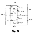
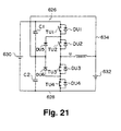
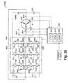
- Fig. 19 is the schematic diagram showing the outline of the configuration of the mechanical power outputting apparatus 620 of the embodiment 5 of the present invention.
- the mechanical power outputting apparatus 620 of the embodiment 5 comprises a motor 622 driven to rotate by a three-phase alternating current, an inverter circuit 624 capable of converting a direct-current power into a three-phase alternating-current power to supply the converted three-phase alternating-current power to the motor 622, a first direct-current power supply 630 connected between the positive pole bus 626 and the negative pole bus 628 of the inverter circuit 624, a second direct-current power supply 632 connected between the negative pole bus 628 of the inverter circuit 624 and the neutral point of the motor 622, and an electronic control unit 640 for controlling the whole apparatus as shown in the figure.
- the motor 622 is structured as a synchronous generation dynamo-electric motor that is capable of the generation of electrical energy and is constituted of, for example, a rotor having a permanent magnet affixed on the outer surface and a stator on which three-phase coils are wound.
- the rotating shaft of the motor 622 is the outputting shaft of the mechanical power outputting apparatus 620 of the embodiment 5, and mechanical power is output from the rotating shaft.
- the motor 622 is structured as a generation dynamo-electric motor, the generation of electrical energy can be performed with the motor 622 by the input of mechanical power into the rotating shaft of the motor 622.
- the inverter circuit 624 is configured with twelve transistors TU1-TU4, TV1-TV4 and TW1-TW4 and eighteen diodes DU1-DU6, DV1-DV6 and DW1-DW6.
- the u-phase of the inverter circuit 624 connects the positive pole bus 626 and the negative pole bus 628 in series with four transistors TU1-TU4, and the u-phase of the three phase coils of the motor 622 is connected with the connection point of the transistor TU2 and the transistor TU3.
- connection point of the transistor TU1 and the transistor TU2 and the connection point of the transistor TU3 and the transistor TU4 are connected in series with two diodes DU5 and DU6 the forward direction of which is a direction oriented to the positive pole bus 626 side from the negative pole bus 628 side.
- the connection point of the diode DU5 and the diode DU6 is connected with the neutral point of the motor 622.
- diodes DU1-DU4 for circulation are attached to the respective transistors TU1-TU4, respectively.
- the v-phase and the w-phase of the inverter circuit 624 are configured similarly to the u-phase thereof.
- the positive pole bus 626 and the negative pole bus 628 of the inverter circuit 624 are connected in series with two capacitors C1 and C2.
- the connection point of the capacitor C1 and the capacitor C2 is connected with the neutral point of the motor 622 with a connection line 634.
- the first direct-current power supply 630 and the second direct-current power supply 632 are structured as a secondary battery, for example, in a nickel hydrogen series or in a lithium ion series.
- the voltage V1 between the terminals of the first direct-current power supply 630 and the voltage V2 between the terminals of the second direct-current power supply 632 are adjusted so that the voltage V1 is twice as large as the voltage V2. Consequently, when the neutral point of the motor 622 is taken as a reference, the electrical potential of the positive pole bus 626 is V1 - V2, and the electrical potential of the negative pole bus 628 is -V2.
- the voltage of the positive pole bus 626 is supposed to be 1/2 VB and the voltage of the negative pole bus 628 is supposed to be -1/2 VB for the following consideration.
- the electronic control unit 640 is composed as a microprocessor centering on a CPU 642, and the electronic control unit 640 comprises a ROM 644 that stores a processing program, a RAM 646 that stores data temporarily and an input/output port (not shown).
- the current of each phase from current sensors 652, 654 and 656 attached to each phase (u, v and w) of the three-phase coils of the motor 622, a neutral point current from a current sensor 658 attached to the neutral point of the motor 622, a rotation angle of the rotor of the motor 622 from the rotation angle sensor 660 attached to the rotating shaft of the motor 622, and the like are input into the electronic control unit 640 through the input port thereof.
- any one of the current sensors 652, 654, 656 and 658 for obtaining each phase current and the neutral point current are equipped, any one of the current sensors 652, 654, 656 and 658 can be omitted, and any one of them may be used as a sensor for abnormal detection use only.
- the control signals for performing the switching control of the transistors TU1-TU4, TV1-TV4 and TW1-TW4 of the inverter circuit 624, and the like are output through the output port of the electronic control unit 640.
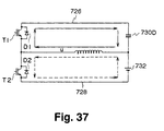
- Fig. 20 is a circuit diagram of the mechanical power outputting apparatus 620 of the embodiment 5 when the u-phase is in a state where transistors TU1 and TU2 are turned on and transistors TU3 and TU4 are turned off. In this state, the voltage (1/2 VB) of positive pole bus 626 operates on the u-phase of the motor 622.
- Fig. 20 is a circuit diagram of the mechanical power outputting apparatus 620 of the embodiment 5 when the u-phase is in a state where transistors TU1 and TU2 are turned on and transistors TU3 and TU4 are turned off. In this state, the voltage (1/2 VB) of positive pole bus 626 operates on the u-phase of the motor 622.
- Fig. 20 is a circuit diagram of the mechanical power outputting apparatus 620 of the embodiment 5 when the u-phase is in a state where transistors TU1 and TU2 are turned on and transistors TU3 and TU4 are turned off. In this state, the voltage (1/2 VB
- FIG. 21 is a circuit diagram of the mechanical power outputting apparatus 620 of the embodiment 5 when the u-phase is in a state where the transistors TU1 and TU2 are turned off and the transistors TU3 and TU4 are turned on. In this state, the voltage (-1/2 VB) of the negative pole bus 628 operates on the u-phase of the motor 622.
- Fig. 22 is a circuit diagram of the mechanical power outputting apparatus 620 of the embodiment 5 when the u-phase is in a state where the transistors TU1 and TU4 are turned off and the transistors TU2 and TU3 are turned on. In this state, the voltage of the neutral point of the motor 622 (reference voltage: zero) operates.
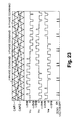
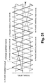
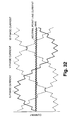
- Fig. 23 is an explanatory view for illustrating the situation of the acquisition of the pseudo-three-phase alternating current by the switching of the transistors TU1-TU4, TV1-TV4 and TW1-TW4 of the inverter circuit 624.
- the states of the turning on or off of the respective transistors TU1-TU4, TV1-TV4 and TW1-TW4 are determined by the comparison of the magnitude of each of the respective phase commands (u, v and w) different from each other by 120 degrees with triangular carrier waves CAR1 and CAR2 that are hierarchically classified in two steps.
- the voltage (zero) of the neutral point of the motor 622 is made to operate on the u-phase of the three-phase coils.
- the command value Vu* is smaller than the triangular carrier wave CAR2
- the transistors TU1 and TU2 are turned off and the transistors TU3 and TU4 are turned on as shown in Fig. 21, and then the voltage (-1/2 VB) of the negative pole bus 628 is made to operate on the u-phase of the three-phase coils.
- each phase command, a triangular carrier wave, the PWM waveform of each phase (Vu, Vv and Vw) and the zero voltage vectors in a conventional mechanical power outputting apparatus that performs the PWM control thereof by means of two steps of voltage levels of a positive pole bus voltage (1/2 VB) and a negative pole bus voltage (-1/2 VB) are shown in Fig. 24.
- the mechanical power outputting apparatus 620 of the embodiment 5 can decrease the frequency of the outputs of the zero voltage vectors in a great extent by performing the PWM control thereof with voltage levels of three steps in comparison with the conventional mechanical power outputting apparatus that performs the PWM control thereof with the voltage levels of two steps. Consequently, the outputs of the zero voltage vectors and the current pulsations generated by the fixation of the electrical potential of the neutral point of the motor 622 can be decreased.
- the frequency of the outputs of the zero voltage vectors can be decreased to a great extent by the execution of the PWM control thereof with voltage levels of three steps.
- the current pulsations that can be generated at the neutral point of the motor 622 with the output of the zero voltage vector can be decreased, and the loss of the motor 622 can be suppressed.
- the second direct-current power supply 632 is attached to connect the negative pole bus 628 of the inverter circuit 624 with the neutral point of the motor 622
- the second direct-current power supply 632 may be attached to connect the positive pole bus 626 of the inverter circuit 624 with the neutral point of the motor 622.
- the first direct-current power supply 630 having the voltage V1 being twice as large as the voltage V2 of the second direct-current power supply 632 is attached to connect the positive pole bus 626 with the negative pole bus 628 of the inverter circuit 624
- a first direct-current power supply 630B having the same voltage as the voltage V2 of the second direct-voltage power supply 632 may be attached to connect the positive pole bus 626 of the inverter circuit 624 and the neutral point of the motor 622 as the modified mechanical power outputting apparatus 6208 of Fig. 25.
- the reason for this is that the modified mechanical power outputting apparatus 620B is electrically equivalent to the mechanical power outputting apparatus 620 of the embodiment 5.
- the first direct-current power supply 630 connecting the positive pole bus 626 and the negative pole bus 628 of the inverter circuit 624 is provided, a capacitor 630C may be provided in place of the first direct-current power supply 630 as the modified mechanical power outputting apparatus 620C of Fig. 26.
- the modified mechanical power outputting apparatus 620C shown in Fig. 26 is equipped with a voltage sensor 662 for detecting the voltage Vc between the terminals of the capacitor 630C, and a detection signal from the voltage sensor 662 is inputted to the electronic control unit 640 through the input port thereof.
- FIG. 27 is a circuit diagram of the modified mechanical power outputting apparatus 620C when the leakage inductance of the three-phase coils of a motor 622 is noticed.
- a state in which the transistors TU3 and TU4 of the u-phase of the inverter circuit 624 are turned on is considered, a short circuit shown by the broken arrows in the figure is formed, and the u-phase of the three-phase coils of the motor 622 functions as a reactor.
- the transistor TU3 or TU4 is turned off, the energy that is stored in the u-phase of the three-phase coils that functions as a reactor is stored in the capacitor 630C through the charging circuit shown by the solid arrows in the figure.
- the charged voltage in this case can be higher than the supply voltage of the second direct-current power supply 632.
- the second direct-current power supply 632 can also be charged by means of the electrical potential of the capacitor 630C in the circuit. Consequently, the circuit can be regarded as a step-up and step-down chopper circuit that steps up the energy of the second direct-current power supply 632 to store it in the capacitor 630C and can charge the second direct-current power supply 632 by means of the electrical potential of the capacitor 630C.
- the capacitor 630C can be charged by the execution of the turning on and off of the transistors TU3, TU4, TV3, TV4, TW3 and TW4, and the second direct-current power supply 632 can be charged by means of the electrical potential of the capacitor 630C.
- the voltage Vc between the terminals of the capacitor 630C can also be made to be twice as large as the voltage V2 of the second direct-current power supply 632. If the voltage Vc between the terminals of the capacitor 630C is thus made to be twice as large as the voltage V2 of the second direct-current power supply 632, the modified mechanical power outputting apparatus 620C shown in the Fig.
- the motor 622 can be driven by the supply of a pseudo-three-phase alternating current generated by the switching control of the transistors TU1-TU4, TV1-TV4 and TW1-TW4 that compose the inverter circuit 624 and the charging of the capacitor 630C can be performed with a direct-current component
- the three-phase alternating current including the direct-current component can be supplied to the motor 622 by the offsetting of the electric potentials of a pseudo-three-phase alternating current to the plus side or the minus side.
- the modified mechanical power outputting apparatus 620C can perform the control similar to the PWM control of each phase of the mechanical power outputting apparatus 620 of the embodiment 5 by offsetting each phase command shown in Fig. 23 to the plus side or the minus side, and can control the voltage Vc between the terminals of the capacitor 630C.
- the modified mechanical power outputting apparatus 620C can also possess advantages similar to those of the mechanical power outputting apparatus 620 of the embodiment 5.
- the mechanical power outputting apparatus 620 of the embodiment 5 is equipped with the first direct-current power supply 630 connecting the positive pole bus 626 and the negative pole bus 628 of the inverter circuit 624
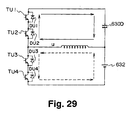
- the mechanical power outputting apparatus may be equipped with a capacitor 630D connecting the positive pole bus 626 of the inverter circuit 624 and the neutral point of the motor 622 in place of the first direct-current power supply 630 as the modified mechanical power outputting apparatus 620D of Fig. 28.
- Fig. 29 is a circuit diagram of a modified mechanical power outputting apparatus 620D when the leakage inductance of the three-phase coils of the motor 622 is noticed.
- a state in which the transistors TU3 and TU4 of the u-phase of the inverter circuit 624 are turned on is considered, a short circuit shown by the broken arrows in the figure is formed, and the u-phase of the three-phase coils of the motor 622 functions as a reactor.
- the circuit can be regarded as a chopper circuit that steps up the energy of the second direct-current power supply 632 to store it in the capacitor 630D and can charge the second direct-current power supply 632 by means of the electrical potential of the capacitor 630D.
- the capacitor 630D can be charged by the execution of the turning on and off of the transistors TU1-TU4, TV1-TV4 and TW1-TW4, and the second direct-current power supply 632 can be charged by means of the electrical potential of the capacitor 630D.
- 29 is in a state where a direct-current power supply that has a voltage twice as large as the voltage V2 and is composed of the capacitor 630D and the second direct-current power supply 632 is connected between the positive pole bus 626 and the negative pole bus 628, i.e. the state where a direct-current power supply corresponding to the first direct-current power supply 630 of the mechanical power outputting apparatus 620 of the embodiment 5 is connected between the positive pole bus 626 and the negative pole bus 628. Then, the motor 622 can be driven similarly to the mechanical power outputting apparatus 620 of the embodiment 5.
- the motor 622 can be driven by the supply of a pseudo-three-phase alternating current generated by the aforesaid switching control of the transistors TU1-TU4, TV1-TV4 and TW1-TW4 that compose the inverter circuit 624 and the charging of the capacitor 630D can be performed with a direct-current component
- the three-phase alternating current including the direct-current component can be supplied to the motor 622 by the offsetting of the electric potentials of the pseudo-three-phase alternating current to the plus side or the minus side.
- the modified mechanical power outputting apparatus 620D can perform the control similar to the PWM control of each phase of the mechanical power outputting apparatus 620 of the embodiment 5 by offsetting each phase command shown in Fig. 23 to the plus side or the minus side and can control the voltage Vc between the terminals of the capacitor 630D similarly to the modified mechanical power outputting apparatus 620C.
- the modified mechanical power outputting apparatus 620D can also possess advantages similar to those of the mechanical power outputting apparatus 620 of the embodiment 5.
- the intermediate connection point of each phase of the diodes DU5, DU6, DV5, DV6, DW5 and DW6 is connected with the intermediate connection point of the capacitors C1 and C2 and is connected with the neutral point of the motor 622 with the connection line 634
- the intermediate connection point of each phase of the diodes DU5, DU6, DV5, DV6, DW5 and DW6 may simply be connected with the neutral point of the motor 622 with the connection line 634 without being equipped with the capacitors C1 and C2
- the intermediate connection point of each phase of the diodes DU5, DU6, DV5, DV6, DW5 and DW6 may simply be connected with the intermediate connection point of the capacitors C1 and C2 without being connected with the neutral point of the motor 622 with the connection line 634.
- the appearance frequency of the zero voltage vectors is decreased by the execution of the PWM control of the voltage levels of three steps
- the appearance frequency of the zero voltage vectors may be decreased by the execution of the PWM control of the voltage levels of four steps or more.
- the motor driven by the three-phase alternating current is used
- a motor driven by n-phase alternating current may be used.
- the appearance frequency of the zero voltage vectors may be decreased by the execution of the PWM control by the voltage levels of three steps or four steps or more.
- Fig. 30 is a schematic diagram showing the outline of the configuration of the mechanical power outputting apparatus 720 of the embodiment 6.
- the mechanical power outputting apparatus 720 of the embodiment 6 comprises, as shown in the figure, a motor 722 driven to rotate by a three-phase alternating current, an inverter circuit 724 capable of converting direct-current power into three-phase alternating-current power to supply it to the motor 722, a first direct-current power supply 730 connected between a positive pole bus 726 and a negative pole bus 728 of the inverter circuit 724, a second direct-current power supply 732 connected between the negative pole bus 728 of the inverter circuit 724 and the neutral point of the motor 722, and an electronic control unit 740 to control the whole apparatus.
- the motor 722 is, like the motor 622 of the mechanical power outputting apparatus of the embodiment 5, composed as a synchronous generation dynamo-electric motor that is capable of generating electrical energy and is constituted of a rotor on the outer surface of which a permanent magnet is affixed and a stator on which three-phase coils are wound.
- the inverter circuit 724 is composed of six transistors T1-T6 and six diodes D1-D6.
- the six transistors T1-T1 are arranged as three pairs of two between the positive pole bus 726 and the negative pole bus 728 so that one of the paired transistors is on the source side and the other of them is on the sink side, respectively, and each of the three-phase coils (u, v and w) of the motor 722 is connected with each of the connection points of the pairs.
- the three-phase coils of the motor 722 form a rotating magnetic field that can drive the motor 722 to rotate by the PWM control of the voltage levels of two steps of the voltage of the positive pole bus 726 and the voltage of the negative pole bus 728.
- the first direct-current power supply 730 and the second direct-current power supply 732 are also structured as a secondary battery, for example, in a nickel hydrogen series or in a lithium ion series similarly to the fist direct-current power supply 630 and the second direct-current power supply 632.
- the voltage V1 between the terminals of the first direct-current power supply 730 and the voltage V2 between the terminals of the second direct-current power supply 732 are adjusted so that the voltage V1 is about twice as large as the voltage V2.
- the electrical potential of the positive pole bus 726 is V1 - V2
- the electrical potential of the negative pole bus 728 is -V2 similarly to the case of the mechanical power outputting apparatus 620 of the embodiment 5.
- the voltage of the positive pole bus 726 taken to be 1/2 VB and the voltage of the negative pole bus 728 is taken to be -1/2 VB for the following consideration.
- the electronic control unit 740 is composed as a microprocessor centering on a CPU 742, and the electronic control unit 740 comprises a ROM 744 that stores a processing program, a RAM 746 that temporarily stores data and an input/output port (not shown) similarly to the electronic control unit 640 of the mechanical power outputting apparatus 620 of the embodiment 5.
- the current of each phase from current sensors 752, 754 and 756 attached to each phase (u, v and w) of the three-phase coils of the motor 722, a neutral point current from a current sensor 758 attached to the neutral point of the motor 722, a rotation angle of the rotor of the motor 722 from a rotation angle sensor 760 attached to the rotating shaft of the motor 722, a command value with respect to the action of the motor 722, and the like, are input into the electronic control unit 740 through the input port thereof.
- the control signals for performing the switching control of the transistors T1-T6 of the inverter circuit 724, and the like are output through the output port of the electronic control unit 740.
- Fig. 31 is the explanatory view for illustrating an example of the modulated wave of each phase and the carrier wave of each phase for the use of the PWM control by the electronic control unit 740 of the mechanical power outputting apparatus 720 of the embodiment 6.
- any of the u-phase carrier wave, the v-phase carrier wave and the w-phase carrier wave is a triangular wave and each has a phase different from the other by 120 degrees.
- any of the u-phase modulated wave, the v-phase modulated wave and the w-phase modulated wave is formed on the basis of a command of each phase. Because each phase is similar, although it is different in phase, the description will be given for the u-phase.
- the transistor T1 is turned on and the transistor T2 is turned off, and thereby the voltage (1/2 VB) of the positive pole bus 726 is operated on the u-phase of the three-phase coils of the motor 722.
- the transistor T1 is turned off and the transistor T2 is turned on, and thereby the voltage (-1/2 VB) of the negative pole bus 728 is operated on the u-phase of the three-phase coils of the motor 722.
- the PWM control by the voltage levels of two steps can be performed similarly to the conventional mechanical power outputting apparatus.
- waveforms of the PWM control by each phase modulated wave and each phase carrier wave can be similarly obtained.
- the carrier wave of each phase is made to be different in phase from each other by 120 degrees, the waveforms do not take the waveform of each phase (Vu, Vv and Vw) of Fig. 24, and thereby the appearance frequency of the zero voltage vectors becomes small.
- Fig. 32 is the explanatory view for illustrating the currents flowing through each phase coil and the neutral point of the motor 722 at the time of the switching base on the modulated wave of each phase and the carrier wave of each phase of Fig. 31.
- each phase current becomes a pseudo-three-phase alternating current having a phase different from each other by 120 degrees
- the current at the neutral point of the motor 722 is settled within small amplitudes in the vicinity of zero.
- the transistors of each phase of the inverter circuit 724 are switched on the basis of the modulated wave of each phase based on the carrier wave of each phase different in phase from each other by 120 degrees and the commands of each phase command, and thereby the appearance frequency of the zero voltage vectors can be decreased.
- the current pulsations that can be generated at the neutral point of the motor 722 with the outputs of the zero voltage vectors can be decreased, and the loss of the motor 722 can be suppressed.
- the second direct-current power supply 732 is attached to connect the negative pole bus 728 of the inverter circuit 724 with the neutral point of the motor 722, the second direct-current power supply 732 may be attached to connect the positive pole bus 726 of the inverter circuit 724 with the neutral point of the motor 722.
- the first direct-current power supply 730 having the voltage V1 being twice as large as the voltage V2 of the second direct-current power supply 732 is attached to connect the positive pole bus 726 with the negative pole bus 728 of the inverter circuit 724
- a first direct-current power supply 730B having the same voltage as the voltage V2 of the second direct-voltage power supply 732 may be attached to connect the positive pole bus 726 of the inverter circuit 724 and the neutral point of the motor 722 as the modified mechanical power outputting apparatus 720B of Fig. 33.
- the reason for this is that the modified mechanical power outputting apparatus 720B is electrically equivalent to the mechanical power outputting apparatus 720 of the embodiment 6.
- the first direct-current power supply 730 connecting the positive pole bus 726 and the negative pole bus 728 of the inverter circuit 724 is provided, a capacitor 730C may be provided in place of the first direct-current power supply 730 as the modified mechanical power outputting apparatus 720C of Fig. 34.
- the modified mechanical power outputting apparatus 720C shown in Fig. 34 is equipped with a voltage sensor 762 for detecting the voltage Vc between the terminals of the capacitor 730C, and a detection signal from the voltage sensor 762 is inputted to the electronic control unit 740 through the input port thereof.
- FIG. 35 is the circuit diagram of the modified mechanical power outputting apparatus 720C when the leakage inductance of the three-phase coils of a motor 722 is noticed.
- the circuit diagram shows a configuration in which the transistors TU1 and TU2 are replaced with one transistor T1 and transistors TU3 and TU4 are replaced with one transistor T2 in the circuit diagram shown in Fig. 27. Consequently, the circuit shown in Fig. 35 can be regarded as a step-up and step-down chopper circuit that steps up the energy of the second direct-current power supply 732 to store it in the capacitor 730C and can charge the second direct-current power supply 732 by means of the electrical potential of the capacitor 730C similarly to the circuit shown in Fig. 27.
- the capacitor 730C can be charged by the execution of the turning on and off of the transistors T2, T4 and T6, and the second direct-current power supply 732 can be charged by means of the electrical potential of the capacitor 730C. Then, the control of the voltage Vc between the terminals of the capacitor 730C and the driving control of the motor 722 can be performed simultaneously by the offsetting of the electrical potential of a pseudo-three-phase alternating current as described with respect to the modified mechanical power outputting apparatus 620C.
- the modified mechanical power outputting apparatus 720C can perform the control similar to the PWM control of each phase of the mechanical power outputting apparatus 720 of the embodiment 6 by offsetting each phase modulated wave shown in Fig. 31 to the plus side or the minus side, and can control the voltage Vc between the terminals of the capacitor 730C.
- the modified mechanical power outputting apparatus 720C can also possess advantages similar to those of the mechanical power outputting apparatus 720 of the embodiment 6.
- the mechanical power outputting apparatus 720 of the embodiment 6 is equipped with the first direct-current power supply 730 connecting the positive pole bus 726 and the negative pole bus 728 of the inverter circuit 724
- the mechanical power outputting apparatus may be equipped with a capacitor 730D connecting the positive pole bus 726 of the inverter circuit 724 and the neutral point of the motor 722 in place of the first direct-current power supply 730 as the modified mechanical power outputting apparatus 720D of Fig. 36.
- the modified mechanical power outputting apparatus 720D shown in Fig. 36 is also equipped with the voltage sensor 762 for detecting the voltage Vc between the terminals of the capacitor 730D, and the detection signal of the voltage sensor 762 is input into the electronic control unit 740 through the input port.
- the circuit shown in Fig. 37 is the circuit diagram of the modified mechanical power outputting apparatus 720D when the leakage inductance of the three-phase coils of the motor 722 is noticed.
- the circuit diagram shows a configuration in which the transistors TU1 and TU2 are replaced with one transistor T1 and the transistors TU3 and TU4 are replaced with one transistor T2 in the circuit diagram shown in Fig. 29. Consequently, the circuit shown in Fig. 37 can be regarded as a chopper circuit that stores the energy of the second direct-current power supply 732 in the capacitor 730D and can charge the second direct-current power supply 732 by means of the electrical potential of the capacitor 730D similarly to the circuit shown in Fig. 29.
- the capacitor 730D can be charged by the execution of the turning on and off of the transistors T1-T6, and the second direct-current power supply 732 can be charged by means of the electrical potential of the capacitor 730D. Then, the control of the voltage Vc between the terminals of the capacitor 730D and the driving control of the motor 722 can be performed simultaneously by the offsetting of the electrical potential of a pseudo-three-phase alternating current as described with respect to the modified mechanical power outputting apparatus 620D.
- the modified mechanical power outputting apparatus 720D can perform the control similar to the PWM control of each phase of the mechanical power outputting apparatus 720 of the embodiment 6 by offsetting each phase modulated wave shown in Fig. 31 to the plus side or the minus side, and can control the voltage Vc between the terminals of the capacitor 730D.
- the modified mechanical power outputting apparatus 720D can also possess advantages similar to those of the mechanical power outputting apparatus 720 of the embodiment 6.
- the phase of the carrier wave of each phase is made to be different from each other by 120 degrees
- the phase of the carrier wave of each phase may be made to be different from each other by 360/n when a motor of n-phase is used.
- the phase of the carrier wave of each phase should be within an allowed extent of current pulsations, the phase may be angles within an allowed extent including 120 degrees and 360/n degrees.
- the phase of the carrier wave of each phase may be any angle as long as it can make the appearance frequency of the zero voltage vectors small.
- a synchronous generation dynamo-electric motor driven by a square wave voltage of a three-phase alternating current is used as the motors 622 and 722
- any type of dynamo-electric motor driven by a square wave voltage of a polyphase alternating current may be used.
Landscapes
- Engineering & Computer Science (AREA)
- Transportation (AREA)
- Mechanical Engineering (AREA)
- Power Engineering (AREA)
- Chemical & Material Sciences (AREA)
- Combustion & Propulsion (AREA)
- Life Sciences & Earth Sciences (AREA)
- Sustainable Development (AREA)
- Sustainable Energy (AREA)
- Inverter Devices (AREA)
- Electric Propulsion And Braking For Vehicles (AREA)
- Control Of Ac Motors In General (AREA)
Applications Claiming Priority (6)
| Application Number | Priority Date | Filing Date | Title |
|---|---|---|---|
| JP2000190443 | 2000-06-26 | ||
| JP2000190443A JP4298896B2 (ja) | 2000-06-26 | 2000-06-26 | 動力出力装置 |
| JP2000194107 | 2000-06-28 | ||
| JP2000194107A JP2002010670A (ja) | 2000-06-28 | 2000-06-28 | 動力出力装置 |
| JP2000199787A JP4575555B2 (ja) | 2000-06-30 | 2000-06-30 | 動力出力装置 |
| JP2000199787 | 2000-06-30 |
Publications (3)
| Publication Number | Publication Date |
|---|---|
| EP1168593A2 true EP1168593A2 (fr) | 2002-01-02 |
| EP1168593A3 EP1168593A3 (fr) | 2003-05-14 |
| EP1168593B1 EP1168593B1 (fr) | 2014-10-29 |
Family
ID=27343840
Family Applications (1)
| Application Number | Title | Priority Date | Filing Date |
|---|---|---|---|
| EP01115029.9A Expired - Lifetime EP1168593B1 (fr) | 2000-06-26 | 2001-06-20 | Appareil pour production d'énergie mécanique et onduleur |
Country Status (2)
| Country | Link |
|---|---|
| US (1) | US6518736B2 (fr) |
| EP (1) | EP1168593B1 (fr) |
Cited By (8)
| Publication number | Priority date | Publication date | Assignee | Title |
|---|---|---|---|---|
| US6930460B2 (en) * | 2002-02-05 | 2005-08-16 | Toyota Jidosha Kabushiki Kaisha | Load driver with power storage unit |
| EP1603224A1 (fr) * | 2003-03-11 | 2005-12-07 | Toyota Jidosha Kabushiki Kaisha | Dispositif de moteur, dispositif de commande de vehicule automobile hybride utilisant un tel moteur, et support d'enregistrement lisible par ordinateur pour entrainer l'execution de la commande d'un moteur par un ordinateur |
| WO2006035959A1 (fr) * | 2004-09-29 | 2006-04-06 | Toyota Jidosha Kabushiki Kaisha | Appareil de puissance delivree et vehicule comportant un tel appareil |
| EP1531078A3 (fr) * | 2003-11-14 | 2006-07-05 | Nissan Motor Co., Ltd. | Système et procédé de commande pour véhicule motorisé à quatre roues motrices |
| CN100410097C (zh) * | 2004-11-30 | 2008-08-13 | 丰田自动车株式会社 | 交流电压输出装置和装有这种交流电压输出装置的车辆 |
| CN103078590A (zh) * | 2011-10-25 | 2013-05-01 | 株式会社电装 | 用于马达-发电机的控制装置 |
| EP2553795A4 (fr) * | 2010-03-29 | 2017-05-17 | Ramu, Inc. | Topologie de circuit de commande et commande de moteurs sans balais à aimants permanents |
| EP3455932B1 (fr) * | 2016-05-09 | 2023-07-19 | Fraunhofer-Gesellschaft zur Förderung der angewandten Forschung e.V. | Dispositif et procédé pour produire une tension alternative |
Families Citing this family (32)
| Publication number | Priority date | Publication date | Assignee | Title |
|---|---|---|---|---|
| JP3749645B2 (ja) * | 1999-12-27 | 2006-03-01 | 株式会社ケーヒン | 携帯用発電機 |
| EP2083498B1 (fr) * | 2000-01-28 | 2010-12-08 | Cummins Generator Technologies Limited | Système de génération électrique CA |
| US6518736B2 (en) * | 2000-06-26 | 2003-02-11 | Toyota Jidosha Kabushiki Kaisha | Mechanical power outputting apparatus and inverter apparatus |
| JP4721538B2 (ja) | 2000-06-30 | 2011-07-13 | トヨタ自動車株式会社 | 動力出力装置 |
| DE10119624A1 (de) * | 2001-04-20 | 2002-11-21 | Aloys Wobben | Verfahren zum Betreiben einer Windenergieanlage |
| CN100353055C (zh) | 2001-04-20 | 2007-12-05 | 阿洛伊斯·沃本 | 风力涡轮机及其工作方法 |
| DE10215822B4 (de) * | 2002-04-10 | 2013-03-07 | Sew-Eurodrive Gmbh & Co. Kg | Umrichtersystem und Verfahren |
| JP3582523B2 (ja) * | 2002-09-17 | 2004-10-27 | トヨタ自動車株式会社 | 電気負荷装置、異常処理方法、および電気負荷の異常処理をコンピュータに実行させるためのプログラムを記録したコンピュータ読取り可能な記録媒体 |
| US20040085046A1 (en) * | 2002-11-01 | 2004-05-06 | General Electric Company | Power conditioning system for turbine motor/generator |
| JP2004236424A (ja) * | 2003-01-30 | 2004-08-19 | Toyota Motor Corp | 動力出力装置、モータ駆動方法およびモータの駆動制御をコンピュータに実行させるためのプログラムを記録したコンピュータ読取り可能な記録媒体 |
| JP2004336885A (ja) * | 2003-05-07 | 2004-11-25 | Toyota Motor Corp | 動力出力装置、モータ駆動方法およびモータの駆動制御をコンピュータに実行させるためのプログラムを記録したコンピュータ読取り可能な記録媒体 |
| SE525582C2 (sv) * | 2003-06-30 | 2005-03-15 | Dometic Sweden Ab | En inverter och en metod för att strömförsörja en växelströmsapparat i ett fordon |
| JP4679891B2 (ja) * | 2004-11-30 | 2011-05-11 | トヨタ自動車株式会社 | 交流電圧発生装置および動力出力装置 |
| JP4275614B2 (ja) * | 2004-12-10 | 2009-06-10 | 三菱電機株式会社 | 車両用回転電機 |
| JP4211806B2 (ja) * | 2006-06-07 | 2009-01-21 | トヨタ自動車株式会社 | 車両駆動システムおよびそれを備える車両 |
| JP4179378B2 (ja) * | 2007-01-04 | 2008-11-12 | トヨタ自動車株式会社 | 車両の駆動制御装置、および、車両 |
| JP4380755B2 (ja) * | 2007-10-10 | 2009-12-09 | 株式会社デンソー | 回転電機装置 |
| JP4708483B2 (ja) * | 2008-03-18 | 2011-06-22 | 株式会社デンソー | 同期電動機の駆動装置 |
| JP4462366B2 (ja) * | 2008-04-01 | 2010-05-12 | トヨタ自動車株式会社 | 動力出力装置およびこれを備える車両並びに動力出力装置の制御方法 |
| JP4561865B2 (ja) * | 2008-04-15 | 2010-10-13 | 株式会社デンソー | 同期電動機の駆動装置 |
| JP5412974B2 (ja) * | 2009-03-13 | 2014-02-12 | 株式会社デンソー | 三相交流同期電動機の駆動装置 |
| JP5372705B2 (ja) | 2009-11-04 | 2013-12-18 | 株式会社日立産機システム | 電力変換装置 |
| DE102010042328A1 (de) * | 2010-10-12 | 2012-04-12 | Robert Bosch Gmbh | Verfahren zum Überwachen des Ladebetriebs eines Energiespeichers in einem Fahrzeug und Ladesystem zum Laden eines Energiespeichers in einem Fahrzeug |
| DE102011085859A1 (de) * | 2011-11-07 | 2013-05-08 | Siemens Aktiengesellschaft | Verfahren und Anordnung zum Betrieb von Synchronmotoren |
| DE102011085853A1 (de) * | 2011-11-07 | 2013-05-08 | Siemens Aktiengesellschaft | Verfahren und Anordnung zum Betrieb von Synchronmotoren |
| DE102012203525A1 (de) * | 2012-03-06 | 2013-09-12 | Bayerische Motoren Werke Aktiengesellschaft | Fahrzeug mit elektrischer Maschine und Verfahren zum Betreiben dieser |
| WO2014083980A1 (fr) * | 2012-11-28 | 2014-06-05 | 富士電機株式会社 | Système de conversion de puissance et procédé permettant de commander ce dernier |
| US10550816B2 (en) * | 2016-02-17 | 2020-02-04 | General Electric Company | Start/stop system for vehicles and method of making same |
| JP6547672B2 (ja) * | 2016-04-07 | 2019-07-24 | 株式会社豊田自動織機 | 電動機装置 |
| JP6418196B2 (ja) * | 2016-04-15 | 2018-11-07 | トヨタ自動車株式会社 | 電気自動車 |
| CN108427037B (zh) * | 2018-04-16 | 2023-11-24 | 北京动力源科技股份有限公司 | 一种光伏并网逆变器绝缘电阻的监测装置和电子设备 |
| CN112937337A (zh) * | 2021-01-21 | 2021-06-11 | 华为技术有限公司 | 一种充电系统及电动汽车 |
Family Cites Families (15)
| Publication number | Priority date | Publication date | Assignee | Title |
|---|---|---|---|---|
| US5083039B1 (en) * | 1991-02-01 | 1999-11-16 | Zond Energy Systems Inc | Variable speed wind turbine |
| JP3170838B2 (ja) | 1992-01-28 | 2001-05-28 | ブラザー工業株式会社 | 可変リラクタンスモータの駆動装置 |
| JP3063592B2 (ja) * | 1995-05-19 | 2000-07-12 | トヨタ自動車株式会社 | 動力伝達装置およびその制御方法 |
| JP3050141B2 (ja) * | 1996-09-24 | 2000-06-12 | トヨタ自動車株式会社 | 動力出力装置およびその制御方法 |
| JP3000953B2 (ja) * | 1997-03-21 | 2000-01-17 | トヨタ自動車株式会社 | 動力出力装置およびその制御方法 |
| JP3223842B2 (ja) | 1997-06-03 | 2001-10-29 | 富士電機株式会社 | 多相出力電力変換回路 |
| JP3374958B2 (ja) | 1997-07-31 | 2003-02-10 | 富士電機株式会社 | 電力変換回路 |
| DE19823917A1 (de) * | 1997-06-03 | 1998-12-10 | Fuji Electric Co Ltd | Stromrichtervorrichtung |
| JP3365254B2 (ja) | 1997-06-03 | 2003-01-08 | 富士電機株式会社 | 単相−多相電力変換回路 |
| JP3584686B2 (ja) | 1997-07-31 | 2004-11-04 | 富士電機機器制御株式会社 | 電圧形電力変換回路 |
| JP3219039B2 (ja) * | 1997-12-15 | 2001-10-15 | 富士電機株式会社 | 電気自動車の電気システム |
| JP2001165056A (ja) * | 1999-12-13 | 2001-06-19 | Matsushita Electric Ind Co Ltd | 電動圧縮機の駆動装置 |
| JP4460708B2 (ja) * | 2000-03-29 | 2010-05-12 | 株式会社東芝 | エンジンのスタータと発電機とを兼用した永久磁石モータの制御装置 |
| US6518736B2 (en) * | 2000-06-26 | 2003-02-11 | Toyota Jidosha Kabushiki Kaisha | Mechanical power outputting apparatus and inverter apparatus |
| JP3721116B2 (ja) * | 2000-11-14 | 2005-11-30 | 株式会社豊田中央研究所 | 駆動装置,動力出力装置およびその制御方法 |
-
2001
- 2001-06-18 US US09/882,184 patent/US6518736B2/en not_active Expired - Lifetime
- 2001-06-20 EP EP01115029.9A patent/EP1168593B1/fr not_active Expired - Lifetime
Non-Patent Citations (1)
| Title |
|---|
| None |
Cited By (15)
| Publication number | Priority date | Publication date | Assignee | Title |
|---|---|---|---|---|
| US6930460B2 (en) * | 2002-02-05 | 2005-08-16 | Toyota Jidosha Kabushiki Kaisha | Load driver with power storage unit |
| EP1603224A4 (fr) * | 2003-03-11 | 2014-07-16 | Toyota Motor Co Ltd | Dispositif de moteur, dispositif de commande de vehicule automobile hybride utilisant un tel moteur, et support d'enregistrement lisible par ordinateur pour entrainer l'execution de la commande d'un moteur par un ordinateur |
| EP1603224A1 (fr) * | 2003-03-11 | 2005-12-07 | Toyota Jidosha Kabushiki Kaisha | Dispositif de moteur, dispositif de commande de vehicule automobile hybride utilisant un tel moteur, et support d'enregistrement lisible par ordinateur pour entrainer l'execution de la commande d'un moteur par un ordinateur |
| EP1531078A3 (fr) * | 2003-11-14 | 2006-07-05 | Nissan Motor Co., Ltd. | Système et procédé de commande pour véhicule motorisé à quatre roues motrices |
| US7157869B2 (en) | 2003-11-14 | 2007-01-02 | Nissan Motor Co., Ltd. | Control system and control method for motor powered four wheel drive vehicle |
| CN100341724C (zh) * | 2003-11-14 | 2007-10-10 | 日产自动车株式会社 | 由电动机提供动力的四轮驱动车辆的控制系统和控制方法 |
| WO2006035959A1 (fr) * | 2004-09-29 | 2006-04-06 | Toyota Jidosha Kabushiki Kaisha | Appareil de puissance delivree et vehicule comportant un tel appareil |
| AU2005288085B2 (en) * | 2004-09-29 | 2010-10-21 | Aisin Aw Co., Ltd. | Power output apparatus and vehicle having the same |
| US7819213B2 (en) | 2004-09-29 | 2010-10-26 | Toyota Jidosha Kabushiki Kaisha | Power output apparatus and vehicle having the same |
| CN100410097C (zh) * | 2004-11-30 | 2008-08-13 | 丰田自动车株式会社 | 交流电压输出装置和装有这种交流电压输出装置的车辆 |
| EP2553795A4 (fr) * | 2010-03-29 | 2017-05-17 | Ramu, Inc. | Topologie de circuit de commande et commande de moteurs sans balais à aimants permanents |
| CN103078590A (zh) * | 2011-10-25 | 2013-05-01 | 株式会社电装 | 用于马达-发电机的控制装置 |
| US9166504B2 (en) | 2011-10-25 | 2015-10-20 | Denso Corporation | Control apparatus for motor-generator |
| CN103078590B (zh) * | 2011-10-25 | 2016-06-15 | 株式会社电装 | 用于马达-发电机的控制装置 |
| EP3455932B1 (fr) * | 2016-05-09 | 2023-07-19 | Fraunhofer-Gesellschaft zur Förderung der angewandten Forschung e.V. | Dispositif et procédé pour produire une tension alternative |
Also Published As
| Publication number | Publication date |
|---|---|
| US6518736B2 (en) | 2003-02-11 |
| EP1168593B1 (fr) | 2014-10-29 |
| US20020070715A1 (en) | 2002-06-13 |
| EP1168593A3 (fr) | 2003-05-14 |
Similar Documents
| Publication | Publication Date | Title |
|---|---|---|
| EP1168593B1 (fr) | Appareil pour production d'énergie mécanique et onduleur | |
| JP4800402B2 (ja) | 車両搭載用マルチフェーズコンバータ | |
| EP1569324B1 (fr) | Appareil d'agencement, procédé de commande et moyen de stockage de programme pour l'appareil d'agencement et appareil de génération de puissance | |
| US8680794B2 (en) | Load drive system, motor drive system, and vehicle control system | |
| US6262896B1 (en) | Auxiliary power conversion for an electric vehicle using high frequency injection into a PWM inverter | |
| JP4689905B2 (ja) | ブラシレスモータの駆動制御方法及びその装置 | |
| CN103560688A (zh) | 电力变换装置 | |
| JP4721538B2 (ja) | 動力出力装置 | |
| US11431184B2 (en) | Power supply device | |
| US10903772B2 (en) | Multigroup-multiphase rotating-electric-machine driving apparatus | |
| JP3879528B2 (ja) | 電圧変換装置 | |
| JP2021035202A (ja) | 電源装置 | |
| JP4723743B2 (ja) | 動力出力装置 | |
| JP4575555B2 (ja) | 動力出力装置 | |
| JP2006320074A (ja) | 交流電圧出力装置 | |
| JP4269408B2 (ja) | インバータ駆動モータ | |
| JP2005535276A (ja) | 発電機/モータシステム及び前記システムを操作する方法 | |
| JP2002010670A (ja) | 動力出力装置 | |
| JP2006025577A (ja) | ハイブリッド自動車およびハイブリッド用駆動装置 | |
| JP3851208B2 (ja) | インバータ一体型駆動装置 | |
| JP4153760B2 (ja) | モータ回路およびモータ制御方法 | |
| JP2010273512A (ja) | モータ駆動システムおよび車両 | |
| JP4298896B2 (ja) | 動力出力装置 | |
| US11745611B1 (en) | System and method for control of a multi-function electric powertrain | |
| CN114619862B (zh) | 旋转电机单元 |
Legal Events
| Date | Code | Title | Description |
|---|---|---|---|
| PUAI | Public reference made under article 153(3) epc to a published international application that has entered the european phase |
Free format text: ORIGINAL CODE: 0009012 |
|
| 17P | Request for examination filed |
Effective date: 20010713 |
|
| AK | Designated contracting states |
Kind code of ref document: A2 Designated state(s): AT BE CH CY DE DK ES FI FR GB GR IE IT LI LU MC NL PT SE TR |
|
| AX | Request for extension of the european patent |
Free format text: AL;LT;LV;MK;RO;SI |
|
| PUAL | Search report despatched |
Free format text: ORIGINAL CODE: 0009013 |
|
| AK | Designated contracting states |
Designated state(s): AT BE CH CY DE DK ES FI FR GB GR IE IT LI LU MC NL PT SE TR |
|
| AX | Request for extension of the european patent |
Extension state: AL LT LV MK RO SI |
|
| RIC1 | Information provided on ipc code assigned before grant |
Ipc: 7B 60L 11/18 B Ipc: 7H 02P 7/628 A Ipc: 7H 02P 6/08 B |
|
| AKX | Designation fees paid |
Designated state(s): DE FR GB |
|
| 17Q | First examination report despatched |
Effective date: 20090922 |
|
| RAP1 | Party data changed (applicant data changed or rights of an application transferred) |
Owner name: TOYOTA JIDOSHA KABUSHIKI KAISHA |
|
| GRAP | Despatch of communication of intention to grant a patent |
Free format text: ORIGINAL CODE: EPIDOSNIGR1 |
|
| RIC1 | Information provided on ipc code assigned before grant |
Ipc: B60L 11/12 20060101ALI20131022BHEP Ipc: B60K 1/02 20060101ALN20131022BHEP Ipc: B60K 6/46 20071001ALI20131022BHEP Ipc: B60W 10/08 20060101ALI20131022BHEP Ipc: B60L 11/14 20060101ALI20131022BHEP Ipc: H02P 6/08 20060101ALI20131022BHEP Ipc: H02P 27/08 20060101ALI20131022BHEP Ipc: B60K 6/365 20071001AFI20131022BHEP Ipc: B60L 15/02 20060101ALI20131022BHEP |
|
| INTG | Intention to grant announced |
Effective date: 20131127 |
|
| REG | Reference to a national code |
Ref country code: DE Ref legal event code: R079 Ref document number: 60149070 Country of ref document: DE Free format text: PREVIOUS MAIN CLASS: H02P0007628000 Ipc: B60K0006365000 |
|
| GRAP | Despatch of communication of intention to grant a patent |
Free format text: ORIGINAL CODE: EPIDOSNIGR1 |
|
| RIN1 | Information on inventor provided before grant (corrected) |
Inventor name: SHAMOTO, SUMIKAZU Inventor name: MORIYA, KAZUNARI Inventor name: SASAKI, SHOICHI Inventor name: OHTANI, HIROKI Inventor name: KOMATSU, MASAYUKI Inventor name: INAGUMA, YUKIO |
|
| RIC1 | Information provided on ipc code assigned before grant |
Ipc: B60L 11/12 20060101ALI20140326BHEP Ipc: B60K 6/365 20071001AFI20140326BHEP Ipc: B60K 1/02 20060101ALN20140326BHEP Ipc: B60K 6/46 20071001ALI20140326BHEP Ipc: B60W 10/08 20060101ALI20140326BHEP Ipc: B60L 11/14 20060101ALI20140326BHEP Ipc: B60L 15/02 20060101ALI20140326BHEP Ipc: H02P 27/08 20060101ALI20140326BHEP Ipc: H02P 6/08 20060101ALI20140326BHEP |
|
| INTG | Intention to grant announced |
Effective date: 20140409 |
|
| GRAS | Grant fee paid |
Free format text: ORIGINAL CODE: EPIDOSNIGR3 |
|
| GRAA | (expected) grant |
Free format text: ORIGINAL CODE: 0009210 |
|
| AK | Designated contracting states |
Kind code of ref document: B1 Designated state(s): DE FR GB |
|
| REG | Reference to a national code |
Ref country code: GB Ref legal event code: FG4D |
|
| REG | Reference to a national code |
Ref country code: DE Ref legal event code: R096 Ref document number: 60149070 Country of ref document: DE Effective date: 20141211 |
|
| REG | Reference to a national code |
Ref country code: DE Ref legal event code: R084 Ref document number: 60149070 Country of ref document: DE |
|
| REG | Reference to a national code |
Ref country code: DE Ref legal event code: R084 Ref document number: 60149070 Country of ref document: DE Effective date: 20150326 |
|
| REG | Reference to a national code |
Ref country code: DE Ref legal event code: R097 Ref document number: 60149070 Country of ref document: DE |
|
| PGFP | Annual fee paid to national office [announced via postgrant information from national office to epo] |
Ref country code: DE Payment date: 20150616 Year of fee payment: 15 |
|
| PLBE | No opposition filed within time limit |
Free format text: ORIGINAL CODE: 0009261 |
|
| STAA | Information on the status of an ep patent application or granted ep patent |
Free format text: STATUS: NO OPPOSITION FILED WITHIN TIME LIMIT |
|
| 26N | No opposition filed |
Effective date: 20150730 |
|
| GBPC | Gb: european patent ceased through non-payment of renewal fee |
Effective date: 20150620 |
|
| REG | Reference to a national code |
Ref country code: FR Ref legal event code: ST Effective date: 20160229 |
|
| PG25 | Lapsed in a contracting state [announced via postgrant information from national office to epo] |
Ref country code: GB Free format text: LAPSE BECAUSE OF NON-PAYMENT OF DUE FEES Effective date: 20150620 |
|
| PG25 | Lapsed in a contracting state [announced via postgrant information from national office to epo] |
Ref country code: FR Free format text: LAPSE BECAUSE OF NON-PAYMENT OF DUE FEES Effective date: 20150630 |
|
| REG | Reference to a national code |
Ref country code: DE Ref legal event code: R119 Ref document number: 60149070 Country of ref document: DE |
|
| PG25 | Lapsed in a contracting state [announced via postgrant information from national office to epo] |
Ref country code: DE Free format text: LAPSE BECAUSE OF NON-PAYMENT OF DUE FEES Effective date: 20170103 |