EP1167733A2 - Verfahren zum Betrieb eines Verbrennungsmotors mit Abgasturbolader - Google Patents
Verfahren zum Betrieb eines Verbrennungsmotors mit Abgasturbolader Download PDFInfo
- Publication number
- EP1167733A2 EP1167733A2 EP01114914A EP01114914A EP1167733A2 EP 1167733 A2 EP1167733 A2 EP 1167733A2 EP 01114914 A EP01114914 A EP 01114914A EP 01114914 A EP01114914 A EP 01114914A EP 1167733 A2 EP1167733 A2 EP 1167733A2
- Authority
- EP
- European Patent Office
- Prior art keywords
- exhaust gas
- injection
- special operation
- engine
- post
- Prior art date
- Legal status (The legal status is an assumption and is not a legal conclusion. Google has not performed a legal analysis and makes no representation as to the accuracy of the status listed.)
- Granted
Links
Images


Classifications
-
- F—MECHANICAL ENGINEERING; LIGHTING; HEATING; WEAPONS; BLASTING
- F02—COMBUSTION ENGINES; HOT-GAS OR COMBUSTION-PRODUCT ENGINE PLANTS
- F02D—CONTROLLING COMBUSTION ENGINES
- F02D23/00—Controlling engines characterised by their being supercharged
- F02D23/02—Controlling engines characterised by their being supercharged the engines being of fuel-injection type
-
- F—MECHANICAL ENGINEERING; LIGHTING; HEATING; WEAPONS; BLASTING
- F02—COMBUSTION ENGINES; HOT-GAS OR COMBUSTION-PRODUCT ENGINE PLANTS
- F02D—CONTROLLING COMBUSTION ENGINES
- F02D41/00—Electrical control of supply of combustible mixture or its constituents
- F02D41/0002—Controlling intake air
- F02D41/0007—Controlling intake air for control of turbo-charged or super-charged engines
-
- F—MECHANICAL ENGINEERING; LIGHTING; HEATING; WEAPONS; BLASTING
- F02—COMBUSTION ENGINES; HOT-GAS OR COMBUSTION-PRODUCT ENGINE PLANTS
- F02D—CONTROLLING COMBUSTION ENGINES
- F02D41/00—Electrical control of supply of combustible mixture or its constituents
- F02D41/30—Controlling fuel injection
- F02D41/38—Controlling fuel injection of the high pressure type
- F02D41/40—Controlling fuel injection of the high pressure type with means for controlling injection timing or duration
- F02D41/402—Multiple injections
- F02D41/405—Multiple injections with post injections
-
- F—MECHANICAL ENGINEERING; LIGHTING; HEATING; WEAPONS; BLASTING
- F02—COMBUSTION ENGINES; HOT-GAS OR COMBUSTION-PRODUCT ENGINE PLANTS
- F02B—INTERNAL-COMBUSTION PISTON ENGINES; COMBUSTION ENGINES IN GENERAL
- F02B29/00—Engines characterised by provision for charging or scavenging not provided for in groups F02B25/00, F02B27/00 or F02B33/00 - F02B39/00; Details thereof
- F02B29/04—Cooling of air intake supply
- F02B29/0406—Layout of the intake air cooling or coolant circuit
-
- F—MECHANICAL ENGINEERING; LIGHTING; HEATING; WEAPONS; BLASTING
- F02—COMBUSTION ENGINES; HOT-GAS OR COMBUSTION-PRODUCT ENGINE PLANTS
- F02B—INTERNAL-COMBUSTION PISTON ENGINES; COMBUSTION ENGINES IN GENERAL
- F02B37/00—Engines characterised by provision of pumps driven at least for part of the time by exhaust
-
- F—MECHANICAL ENGINEERING; LIGHTING; HEATING; WEAPONS; BLASTING
- F02—COMBUSTION ENGINES; HOT-GAS OR COMBUSTION-PRODUCT ENGINE PLANTS
- F02M—SUPPLYING COMBUSTION ENGINES IN GENERAL WITH COMBUSTIBLE MIXTURES OR CONSTITUENTS THEREOF
- F02M26/00—Engine-pertinent apparatus for adding exhaust gases to combustion-air, main fuel or fuel-air mixture, e.g. by exhaust gas recirculation [EGR] systems
- F02M26/02—EGR systems specially adapted for supercharged engines
- F02M26/04—EGR systems specially adapted for supercharged engines with a single turbocharger
- F02M26/05—High pressure loops, i.e. wherein recirculated exhaust gas is taken out from the exhaust system upstream of the turbine and reintroduced into the intake system downstream of the compressor
-
- F—MECHANICAL ENGINEERING; LIGHTING; HEATING; WEAPONS; BLASTING
- F02—COMBUSTION ENGINES; HOT-GAS OR COMBUSTION-PRODUCT ENGINE PLANTS
- F02M—SUPPLYING COMBUSTION ENGINES IN GENERAL WITH COMBUSTIBLE MIXTURES OR CONSTITUENTS THEREOF
- F02M26/00—Engine-pertinent apparatus for adding exhaust gases to combustion-air, main fuel or fuel-air mixture, e.g. by exhaust gas recirculation [EGR] systems
- F02M26/02—EGR systems specially adapted for supercharged engines
- F02M26/09—Constructional details, e.g. structural combinations of EGR systems and supercharger systems; Arrangement of the EGR and supercharger systems with respect to the engine
- F02M26/10—Constructional details, e.g. structural combinations of EGR systems and supercharger systems; Arrangement of the EGR and supercharger systems with respect to the engine having means to increase the pressure difference between the exhaust and intake system, e.g. venturis, variable geometry turbines, check valves using pressure pulsations or throttles in the air intake or exhaust system
-
- F—MECHANICAL ENGINEERING; LIGHTING; HEATING; WEAPONS; BLASTING
- F02—COMBUSTION ENGINES; HOT-GAS OR COMBUSTION-PRODUCT ENGINE PLANTS
- F02M—SUPPLYING COMBUSTION ENGINES IN GENERAL WITH COMBUSTIBLE MIXTURES OR CONSTITUENTS THEREOF
- F02M26/00—Engine-pertinent apparatus for adding exhaust gases to combustion-air, main fuel or fuel-air mixture, e.g. by exhaust gas recirculation [EGR] systems
- F02M26/13—Arrangement or layout of EGR passages, e.g. in relation to specific engine parts or for incorporation of accessories
- F02M26/17—Arrangement or layout of EGR passages, e.g. in relation to specific engine parts or for incorporation of accessories in relation to the intake system
- F02M26/21—Arrangement or layout of EGR passages, e.g. in relation to specific engine parts or for incorporation of accessories in relation to the intake system with EGR valves located at or near the connection to the intake system
-
- F—MECHANICAL ENGINEERING; LIGHTING; HEATING; WEAPONS; BLASTING
- F02—COMBUSTION ENGINES; HOT-GAS OR COMBUSTION-PRODUCT ENGINE PLANTS
- F02M—SUPPLYING COMBUSTION ENGINES IN GENERAL WITH COMBUSTIBLE MIXTURES OR CONSTITUENTS THEREOF
- F02M26/00—Engine-pertinent apparatus for adding exhaust gases to combustion-air, main fuel or fuel-air mixture, e.g. by exhaust gas recirculation [EGR] systems
- F02M26/13—Arrangement or layout of EGR passages, e.g. in relation to specific engine parts or for incorporation of accessories
- F02M26/22—Arrangement or layout of EGR passages, e.g. in relation to specific engine parts or for incorporation of accessories with coolers in the recirculation passage
- F02M26/23—Layout, e.g. schematics
- F02M26/28—Layout, e.g. schematics with liquid-cooled heat exchangers
-
- Y—GENERAL TAGGING OF NEW TECHNOLOGICAL DEVELOPMENTS; GENERAL TAGGING OF CROSS-SECTIONAL TECHNOLOGIES SPANNING OVER SEVERAL SECTIONS OF THE IPC; TECHNICAL SUBJECTS COVERED BY FORMER USPC CROSS-REFERENCE ART COLLECTIONS [XRACs] AND DIGESTS
- Y02—TECHNOLOGIES OR APPLICATIONS FOR MITIGATION OR ADAPTATION AGAINST CLIMATE CHANGE
- Y02T—CLIMATE CHANGE MITIGATION TECHNOLOGIES RELATED TO TRANSPORTATION
- Y02T10/00—Road transport of goods or passengers
- Y02T10/10—Internal combustion engine [ICE] based vehicles
- Y02T10/12—Improving ICE efficiencies
-
- Y—GENERAL TAGGING OF NEW TECHNOLOGICAL DEVELOPMENTS; GENERAL TAGGING OF CROSS-SECTIONAL TECHNOLOGIES SPANNING OVER SEVERAL SECTIONS OF THE IPC; TECHNICAL SUBJECTS COVERED BY FORMER USPC CROSS-REFERENCE ART COLLECTIONS [XRACs] AND DIGESTS
- Y02—TECHNOLOGIES OR APPLICATIONS FOR MITIGATION OR ADAPTATION AGAINST CLIMATE CHANGE
- Y02T—CLIMATE CHANGE MITIGATION TECHNOLOGIES RELATED TO TRANSPORTATION
- Y02T10/00—Road transport of goods or passengers
- Y02T10/10—Internal combustion engine [ICE] based vehicles
- Y02T10/40—Engine management systems
Definitions
- the invention relates to a method for operating an internal combustion engine with exhaust gas turbocharger, in which between one Normal operation and a special operation can be switched and in special operation at least one main fuel injection and at least one post-fuel injection is provided are.
- a method is known from German Patent DE 197 50 226 C1 known for operating an internal combustion engine, in which a change between a lean operation and a rich operation a diesel engine is possible. Depending on predetermined Switchover criteria is based on lean operation or rich operation of the diesel engine switched. For lean operation and for the fat operation there are separate maps for the operation of the diesel engine saved.
- Modern exhaust gas cleaning systems require a change in the exhaust gas composition from rich to lean. Compared to a normally lean combustion, a rich combustion is required from time to time, for example to regenerate NO x adsorber systems.
- the invention aims at an accelerated boost pressure build-up an internal combustion engine with an exhaust gas turbocharger at the same time optional setting of a rich or lean exhaust gas composition be made possible.
- the post-injection burned in the combustion chamber contributes to the engine load and leads to an increase in the exhaust gas enthalpy. simultaneously can make a setting by means of the fuel injection the exhaust gas composition between rich and lean.
- the quantity and time of the fuel injection are included important setting parameters for engine load, increasing the exhaust gas enthalpy and adjustment of the exhaust gas composition.
- Turbochargers use the exhaust gas enthalpy to on the fresh air side to drive a compressor. After a positive load jump the turbocharger must be accelerated. The necessary Exhaust gas enthalpy can occur in conventional operating processes not be made available immediately as they go through the smoke limit is limited. The method according to the invention generates a higher exhaust gas enthalpy with the same number of smoke and thus accelerates the build-up of boost pressure, i.e. it shortens the turbo lag.
- the problem underlying the invention is also solved by a Method according to the preamble of claim 2 solved, in which in response to a positive load jump between normal operation and that intended to increase the exhaust gas enthalpy Special operation is switched, the fuel post-injection in special operation is set so that it essentially burns in the combustion chamber and an increase in the exhaust gas enthalpy caused and that in special operation at least one further remote post-injection of the fuel is provided is, by means of which essentially a setting of a bold or lean exhaust gas composition occurs.
- a further development of the invention provides that a switchover time between normal operation and special operation and one Main injection quantity depending on the switching time an engine torque, a derivative of the engine torque, an engine speed, a derivation of the engine speed, a driving speed, an inserted gear, a total injection quantity, an air mass in the intake path, a derivative of the Air mass, a water temperature in the cooling system, an outside air temperature, an intake manifold temperature, an exhaust gas temperature, an ambient pressure, an intake manifold pressure and / or one Exhaust gas pressure can be set.
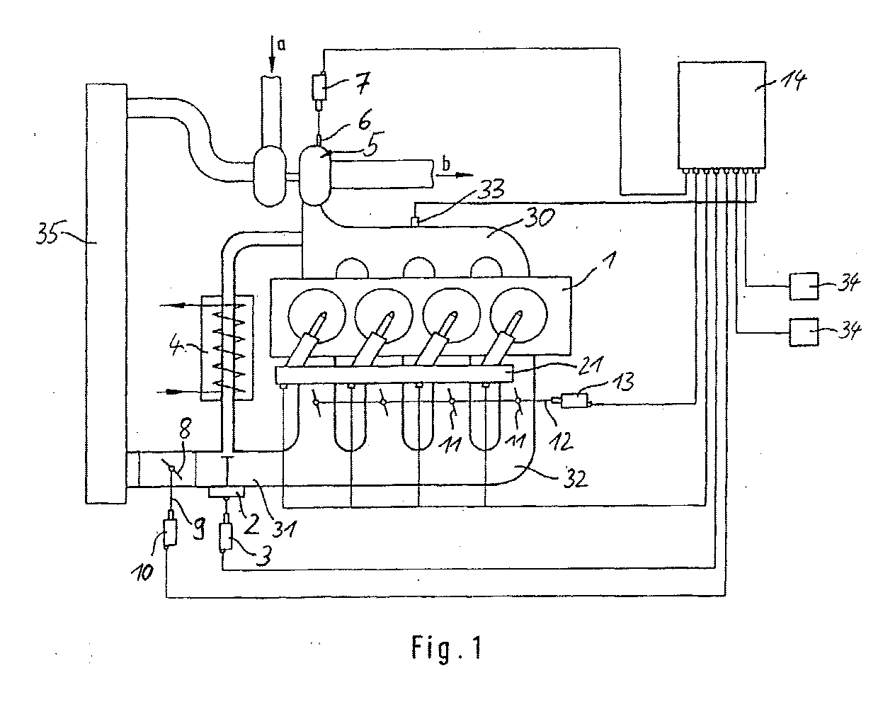
- the diesel engine 1 shown in Fig. 1 can optionally in substoichiometric operation, i.e. Combustion air ratio ⁇ ⁇ 1 or rich combustion, or in stoichiometric or over stoichiometric Operation, i.e. Combustion air ratio ⁇ ⁇ 1 or lean combustion.
- substoichiometric operation i.e. Combustion air ratio ⁇ ⁇ 1 or rich combustion
- stoichiometric or over stoichiometric Operation i.e. Combustion air ratio ⁇ ⁇ 1 or lean combustion.
- an exhaust gas recirculation device is arranged, which is an actuator 2 has.
- the actuator 2 can be operated by an auxiliary operator Actuator 3 in response to signals from an electronic Motor control can be operated.
- an exhaust gas recirculation cooler 4 is provided in the exhaust gas recirculation line.
- the diesel engine is equipped with a supercharger, an exhaust gas turbocharger 5, equipped.
- the exhaust gas turbocharger 5 has Actuator 6 with which an exhaust gas back pressure that flowed through Cross section and / or the exhaust gas volume flowing through can be.
- the actuator 6 with a auxiliary actuator 7 provided as an electric actuator can be trained.
- the auxiliary actuator is dependent on signals from the electronic engine control actuated.
- the one entering a and through the turbocharger 5 compressed fresh air is supplied via an intercooler 35 led.
- Exhaust gas emerges from the exhaust gas turbocharger 5 in the direction arrow b into an exhaust gas cleaning system.
- Throttle device 8 arranged in the intake air line, which can be actuated by means of an actuator 9.
- the Actuator 9 is associated with an auxiliary actuator 10, which also depends on signals from the electronic Motor control can be operated.
- the diesel engine 1 is with a system for reducing the intake cross section provided, the present as one Throttle valve 11 in the intake tract 32 of each individual cylinder is trained.
- the throttle valve 11 is a common one Assigned actuator 12, which is operated by means of an auxiliary power Actuator 13 can be operated. In dependence of Signals from the electronic engine control 14 become the throttle valves 11 operated.
- Switching can be carried out by means of the electronic motor control 14 from a lean burn to a rich burn respectively.
- the motor controller 14 can also be used by one Normal operation can be switched over to a special operation to generate a high exhaust gas enthalpy and a high exhaust gas temperature. By switching to special operation at a positive load jump avoided the so-called turbo lag.
- a rich combustion can thereby by means of the engine control 14 be achieved that an injection course changes will, so an early combustion of the injected fuel quantity is achieved and that a co-burning post-injection is provided in the combustion chamber in terms of quantity and timing is adapted to engine operation.
- the diesel engine is optional with one in quantity and time Fuel injection which can be metered independently of engine operation 33 into the exhaust system.
- Sensors 34 provide signals, for example Pressure and temperature, to the engine control 14.
- the motor controller 14 contains a unit 14a, by means of between lean engine operation and rich engine operation can be switched.
- unit 14a there are maps 17 for rich engine operation and maps 18 for lean Engine operation saved.
- a block 15 there are switching criteria checked and then either by means of a switch 16 a rich or a lean engine operation is set.
- the motor control 14 receives sensor signals via lines 19, which are used to check the switchover criteria in block 15.
- the sensor signals on the lines 19 are from the engine control 14 also used to determine if a positive Load jump is present and in special operation to increase the exhaust gas enthalpy must be switched.
- Via lines 20 gives the engine control 14 corresponding signals to a Injection system 21 and further actuators shown in FIG. 1.
- Switching between normal and special operation takes place according to of the invention based on criteria set forth in the published patent application DE 199 51 096 A1 are listed.
- switchover criteria where the engine control system has a brief switchover realized from normal operation to special operation, if, for example, a certain accelerator pedal position is suggested, which preferably differ from a so-called "kick-down position" differs in vehicles with automatic transmission is known.
- Other switching criteria can also be used
- Signals from an engine control system are evaluated using a Correlate driver request for acceleration. For example can give signals for changing the accelerator pedal position and / or for changing the combustion supplied Amount of fuel within a certain time and / or signals for the difference between one desired by the driver Amount of fuel and one approved by the engine management system Amount of fuel.
- the switchover criteria are preferred to switch to special operation so that the driver e.g. normal acceleration due to a slight accelerator pedal pressure in normal operation and by a correspondingly stronger one Accelerator pedal pressure accelerating with switching in can generate the special operation.
- Switching back to the Normal operation takes place, for example, through a time switch, which after a predetermined period of time, e.g. after a second, triggers a switchover to normal operation.
- a predetermined period of time e.g. after a second
- switching back to normal operation made dependent on it be that a predetermined, in particular map-based Target boost pressure is reached.
- the method proposed according to the invention can thereby be characterize that by the total amount of fuel any number of pre-injections, one or two main injections, a co-burning post-injection and if necessary a further, post-injection in the Combustion chamber is introduced.
- the injection starts of the pre-injections correspond in the inventive method in essentially at the start of injection of the pre-injections normal diesel engine combustion.
- the injection starts correspond to the main injection in the invention Process essentially starting injection of the main injections with normal diesel engine combustion.
- the start of injection of the first post-injection is designed so that a combustion of this post-injection quantity in the combustion chamber takes place, so that the first post-injection on the one hand given engine load contributes and on the other hand a very high Exhaust temperature causes.
- Combustion can also take place via the first post-injection optionally overstoichiometric and understoichiometric be interpreted. For stoichiometric or substoichiometric The combustion can also be interpreted if necessary the further, remote post-injection can be applied.
- the maximum pressure increase in the combustion chamber and the location of the maximum Pressure increases in the combustion chamber correspond to this combustion process roughly the values for normal diesel engine Combustion with pre and main injection.
- the regulation of Engine load is based on the injection quantity participating in the combustion.
- a regulation of the intake manifold pressure is provided, the by means of the throttle valves 11, the exhaust gas turbocharger 5 and, if appropriate by means of the exhaust gas recirculation valve 2 and the exhaust gas turbocharger 5 is done.
- Air mass regulation can also be carried out by means of an air mass meter and the exhaust gas recirculation valve 2, optionally provided by means of the throttle valves 8 and 11 his.
- the air ratio is determined using the exhaust gas recirculation valve 2 and by means of those which burn essentially in the combustion chamber Post-injection and, if necessary, by means of the further, discontinued Post-injection regulated.
- the method according to the invention can accelerate Boost pressure build-up in an internal combustion engine
- Exhaust gas turbocharger is achieved by an essentially post-injection burning in the combustion chamber an increase in Exhaust gas enthalpy is caused. Since this first post-injection in burns substantially in the combustion chamber, it also contributes to the engine load at.
- the exhaust gas turbine can of the exhaust gas turbocharger brought up to speed faster so that a boost pressure is built up faster in the intake path becomes.
- turbo lag is positive Avoid load jump.
- the invention by means of the burning in the combustion chamber Post-injection also a setting of a rich or lean exhaust gas composition.
- This creates regeneration phases of an exhaust gas purification system that has a rich exhaust gas composition require, despite compensation of the turbocharger not interrupted or impaired.
Landscapes
- Engineering & Computer Science (AREA)
- Chemical & Material Sciences (AREA)
- Combustion & Propulsion (AREA)
- Mechanical Engineering (AREA)
- General Engineering & Computer Science (AREA)
- Output Control And Ontrol Of Special Type Engine (AREA)
- Electrical Control Of Air Or Fuel Supplied To Internal-Combustion Engine (AREA)
- Exhaust-Gas Circulating Devices (AREA)
- Exhaust Gas After Treatment (AREA)
- Supercharger (AREA)
Abstract
Description
- Fig. 1
- eine schematische Darstellung eines Dieselmotors mit Abgasturbolader und einer Motorsteuerung zur Realisierung des erfindungsgemäßen Verfahrens und
- Fig. 2
- eine schematische Darstellung zur Verdeutlichung des Aufbaus der in der Fig. 1 dargestellten Motorsteuerung.
- Motormoment und seine Ableitung,
- Motordrehzahl und ihre Ableitung,
- Fahrgeschwindigkeit,
- Gang,
- Gesamteinspritzmenge,
- Luftmasse und ihre Ableitung,
- Wassertemperatur,
- Außenlufttemperatur,
- Saugrohrtemperatur,
- Abgastemperatur,
- Atmosphärendruck,
- Saugrohrdruck und
- Abgasdruck.
- Begrenzungsmoment und Begrenzungsmenge,
- Pedalwertgeber und seine Ableitung,
- Wunschmoment Motor und seine Ableitung,
- Motormoment und seine Ableitung,
- Motordrehzahl und ihre Ableitung,
- Fahrgeschwindigkeit,
- Gang,
- Gesamteinspritzmenge,
- Luftmasse und ihre Ableitung,
- Wassertemperatur,
- Außenlufttemperatur,
- Saugrohrtemperatur,
- Abgastemperatur,
- Atmosphärendruck,
- Ist-Saugrohrdruck,
- Soll-Saugrohrdruck,
- Abgasdruck und
- Fahrertyp.
Claims (5)
- Verfahren zum Betrieb eines Verbrennungsmotors mit Abgasturbolader, bei dem zwischen einem Normalbetrieb und einem Sonderbetrieb umgeschaltet werden kann und im Sonderbetrieb wenigstens eine Kraftstoffhaupteinspritzung und wenigstens eine Kraftstoffnacheinspritzung vorgesehen sind,
dadurch gekennzeichnet, dass in Reaktion auf einen positiven Lastsprung zwischen dem Normalbetrieb und dem zur Erhöhung der Abgasenthalpie vorgesehenen Sonderbetrieb umgeschaltet wird, wobei die Kraftstoffnacheinspritzung im Sonderbetrieb so eingestellt wird, dass sie im wesentlichen im Brennraum verbrennt und eine Erhöhung der Abgasenthalpie sowie eine Einstellung einer fetten oder mageren Abgaszusammensetzung verursacht. - Verfahren zum Betrieb eines Dieselmotors mit Abgasturbolader, wobei zwischen einem Normalbetrieb und einem Sonderbetrieb umgeschaltet werden kann und im Sonderbetrieb wenigstens eine Kraftstoffhaupteinspritzung und wenigstens eine Kraftstoffnacheinspritzung vorgesehen sind,
dadurch gekennzeichnet, dass in Reaktion auf einen positiven Lastsprung zwischen dem Normalbetrieb und dem zur Erhöhung der Abgasenthalpie vorgesehenen Sonderbetrieb umgeschaltet wird, wobei die Kraftstoffnacheinspritzung im Sonderbetrieb so eingestellt wird, dass sie im wesentlichen im Brennraum verbrennt und eine Erhöhung der Abgasenthalpie verursacht und dass im Sonderbetrieb wenigstens eine weitere abgesetzte Nacheinspritzung des Kraftstoffs vorgesehen ist, mittels der im wesentlichen eine Einstellung einer fetten oder mageren Abgaszusammensetzung erfolgt. - Verfahren nach Anspruch 1 oder 2,
dadurch gekennzeichnet,dass im Normal- und Sonderbetrieb in Abhängigkeit des Betriebszustands des Verbrennungsmotors eine Kraftstoffvoreinspritzung vorgesehen ist, deren Einspritzbeginn im Normal- und Sonderbetrieb im wesentlichen gleich ist. - Verfahren nach einem der vorstehenden Ansprüche,
dadurch gekennzeichnet,dass ein Einspritzbeginn der Haupteinspritzung im Normal- und Sonderbetrieb im wesentlichen gleich ist. - Verfahren nach einem der vorstehenden Ansprüche,
dadurch gekennzeichnet,dass eine Umschaltzeit zwischen Normalbetrieb und Sonderbetrieb und eine Haupteinspritzmenge während der Umschaltzeit in Abhängigkeit eines Motormoments, einer Ableitung des Motormoments, einer Motordrehzahl, einer Ableitung der Motordrehzahl, einer Fahrgeschwindigkeit, eines eingelegten Fahrgangs, einer Gesamteinspritzmenge, einer Luftmasse im Ansaugweg, einer Ableitung der Luftmasse, einer Wassertemperatur im Kühlsystem, einer Außenlufttemperatur, einer Saugrohrtemperatur, einer Abgastemperatur, eines Umgebungsdrucks, eines Saugrohrdrucks und/oder eines Abgasdrucks eingestellt werden.
Applications Claiming Priority (2)
| Application Number | Priority Date | Filing Date | Title |
|---|---|---|---|
| DE10029502A DE10029502A1 (de) | 2000-06-21 | 2000-06-21 | Beschleunigter Aufbau des Ladedrucks durch ein mehrstufiges Brennverfahren für Dieselmotoren |
| DE10029502 | 2000-06-21 |
Publications (4)
| Publication Number | Publication Date |
|---|---|
| EP1167733A2 true EP1167733A2 (de) | 2002-01-02 |
| EP1167733A3 EP1167733A3 (de) | 2004-01-02 |
| EP1167733B1 EP1167733B1 (de) | 2004-12-01 |
| EP1167733B2 EP1167733B2 (de) | 2013-11-20 |
Family
ID=7645830
Family Applications (1)
| Application Number | Title | Priority Date | Filing Date |
|---|---|---|---|
| EP01114914.3A Expired - Lifetime EP1167733B2 (de) | 2000-06-21 | 2001-06-20 | Verfahren zum Betrieb eines Verbrennungsmotors mit Abgasturbolader |
Country Status (3)
| Country | Link |
|---|---|
| US (1) | US6619033B2 (de) |
| EP (1) | EP1167733B2 (de) |
| DE (2) | DE10029502A1 (de) |
Cited By (3)
| Publication number | Priority date | Publication date | Assignee | Title |
|---|---|---|---|---|
| FR2840649A1 (fr) * | 2002-06-06 | 2003-12-12 | Renault Sa | Procede d'augmentation de performances d'un moteur suralimente |
| WO2015067845A1 (en) * | 2013-11-07 | 2015-05-14 | Wärtsilä Finland Oy | A combustion engine having two turbochargers connected in series and a method for operating this engine |
| DE102005005559B4 (de) * | 2005-02-07 | 2018-11-15 | Volkswagen Ag | Verfahren zum Betreiben einer Brennkraftmaschine mit Abgasturbolader |
Families Citing this family (19)
| Publication number | Priority date | Publication date | Assignee | Title |
|---|---|---|---|---|
| DE10029502A1 (de) † | 2000-06-21 | 2002-01-31 | Daimler Chrysler Ag | Beschleunigter Aufbau des Ladedrucks durch ein mehrstufiges Brennverfahren für Dieselmotoren |
| DE10201016A1 (de) * | 2002-01-11 | 2003-07-24 | Daimler Chrysler Ag | Verfahren zum Betrieb einer Brennkraftmaschine mit Abgasreinigungsanlage und Brennkraftmaschine |
| US6863058B2 (en) * | 2003-02-03 | 2005-03-08 | Ford Global Technologies, Llc | System and method for reducing NOx emissions during transient conditions in a diesel fueled vehicle |
| US7079938B2 (en) * | 2003-07-25 | 2006-07-18 | Detroit Diesel Corporation | Influence of engine parameters on condensation protection strategies |
| US6934621B2 (en) * | 2003-07-25 | 2005-08-23 | Detroit Diesel Corporation | Re-entry strategy from boost mode to EGR mode |
| US6931837B2 (en) * | 2003-11-06 | 2005-08-23 | International Engine Intellectual Property Company, Llc | Control strategy for lean-to-rich transitions in an internal combustion engine |
| US6948482B2 (en) | 2003-12-09 | 2005-09-27 | Caterpillar Inc. | Engine cylinder temperature control |
| FR2864161B1 (fr) * | 2003-12-18 | 2007-08-10 | Inst Francais Du Petrole | Procede de controle d'un moteur a combustion interne suralimente |
| DE102004025406B4 (de) * | 2004-05-24 | 2015-11-12 | Volkswagen Ag | Verfahren zur Einspritzsteuerung eines Verbrennungsmotors und entsprechend ausgestaltete Motorsteuerung |
| US6990951B1 (en) * | 2004-07-12 | 2006-01-31 | International Engine Intellectual Property Company, Llc | Torque control strategy for a diesel engine during lean-rich modulation using independent fuel injection maps |
| JP2006207417A (ja) * | 2005-01-26 | 2006-08-10 | Denso Corp | 過給機付エンジン制御システム |
| US8126632B2 (en) | 2007-10-26 | 2012-02-28 | Ford Global Technologies, Llc | Engine idle speed and turbocharger speed control |
| US8131446B2 (en) | 2007-10-29 | 2012-03-06 | Ford Global Technologies, Llc | Engine idle speed and turbocharger speed control |
| US8474258B2 (en) * | 2008-09-24 | 2013-07-02 | Deere & Company | Stoichiometric compression ignition engine with increased power output |
| JP5370243B2 (ja) * | 2010-03-31 | 2013-12-18 | マツダ株式会社 | ターボ過給機付きディーゼルエンジンの制御装置 |
| US8886440B2 (en) * | 2010-04-16 | 2014-11-11 | GM Global Technology Operations LLC | Method and system for reducing turbo lag in an engine |
| DE102017200837A1 (de) | 2017-01-19 | 2018-07-19 | Robert Bosch Gmbh | Verfahren und Vorrichtung zum Betreiben eines aufgeladenen kraftstoffgeführten Verbrennungsmotors |
| US11635035B2 (en) * | 2020-10-26 | 2023-04-25 | Tula Technology, Inc. | Fast torque response for boosted engines |
| US11248546B1 (en) * | 2020-10-26 | 2022-02-15 | Tula Technology, Inc. | Fast torque response for boosted engines |
Family Cites Families (32)
| Publication number | Priority date | Publication date | Assignee | Title |
|---|---|---|---|---|
| US4233815A (en) * | 1970-05-05 | 1980-11-18 | Etat Francais | Methods of supercharging a diesel engine, in supercharged diesel engines, and in supercharging units for diesel engines |
| GB1602869A (en) * | 1977-11-25 | 1981-11-18 | Garrett Corp | Turbocharged internal combustion engines |
| US4424676A (en) * | 1979-09-12 | 1984-01-10 | M & W Gear Company | Supplementary fuel injection system for a turbocharged internal combustion engine |
| JPS5681235A (en) * | 1979-12-04 | 1981-07-03 | Nippon Soken Inc | Air-fuel ratio controller for internal combustion engine with supercharger |
| JPS60261941A (ja) * | 1984-06-08 | 1985-12-25 | Mazda Motor Corp | 過給機付エンジン |
| JPS6196138A (ja) * | 1984-10-16 | 1986-05-14 | Ngk Spark Plug Co Ltd | 過給機付内燃機関 |
| FR2605055B1 (fr) * | 1986-10-08 | 1991-09-27 | Daimler Benz Ag | Procede d'injection directe de carburant pour un moteur diesel |
| JP2579936B2 (ja) * | 1987-04-02 | 1997-02-12 | マツダ株式会社 | 過給機付エンジンの空燃比制御装置 |
| JPH0833117B2 (ja) * | 1988-07-07 | 1996-03-29 | 三菱自動車工業株式会社 | 燃料噴射装置 |
| US4953515A (en) * | 1988-11-28 | 1990-09-04 | Fehr William A | Diesel engine secondary fuel injection system |
| US5255655A (en) * | 1989-06-15 | 1993-10-26 | Robert Bosch Gmbh | Fuel injection system for an internal combustion engine |
| JP2677423B2 (ja) * | 1989-07-24 | 1997-11-17 | 富士通テン株式会社 | 内燃機関の燃料噴射量制御方法 |
| US5381659A (en) * | 1993-04-06 | 1995-01-17 | Hughes Aircraft Company | Engine exhaust reburner system and method |
| EP0621400B1 (de) * | 1993-04-23 | 1999-03-31 | Daimler-Benz Aktiengesellschaft | Luftverdichtende Einspritzbrennkraftmaschine mit einer Abgasnachbehandlungseinrichtung zur Reduzierung von Stickoxiden |
| IT1266890B1 (it) * | 1994-07-22 | 1997-01-21 | Fiat Ricerche | Metodo di attivazione di un catalizzatore "denox" in un motore diesel con un sistema di iniezione a collettore comune. |
| DE4439573A1 (de) † | 1994-11-05 | 1996-05-09 | Mtu Friedrichshafen Gmbh | Verfahren zum Betrieb einer Brennkraftmaschine mit einem Abgasturbolader |
| EP0793776B1 (de) * | 1995-09-22 | 2001-12-05 | Robert Bosch Gmbh | Verfahren und vorrichtung zur steuerung einer brennkraftmaschine |
| US5839275A (en) * | 1996-08-20 | 1998-11-24 | Toyota Jidosha Kabushiki Kaisha | Fuel injection control device for a direct injection type engine |
| DE19639172C2 (de) † | 1996-09-24 | 2001-11-08 | Siemens Ag | Kraftstoff-Direkteinspritzverfahren für eine Dieselbrennkraftmaschine |
| JP4010046B2 (ja) * | 1997-06-24 | 2007-11-21 | トヨタ自動車株式会社 | 圧縮着火式内燃機関 |
| DE19747231A1 (de) * | 1997-10-25 | 1999-04-29 | Bosch Gmbh Robert | Verfahren zur Einspritzung von Kraftstoff in die Brennräume einer luftverdichtenden, selbstzündenden Brennkraftmaschine |
| DE19750226C1 (de) * | 1997-11-13 | 1998-10-29 | Daimler Benz Ag | Motorregelsystem für einen Dieselmotor |
| DE19803807A1 (de) † | 1998-01-31 | 1999-08-05 | Volkswagen Ag | Brennkraftmaschine und Verfahren zum Betreiben einer aufgeladenen Brennkraftmaschine |
| FR2775316B1 (fr) † | 1998-02-24 | 2000-06-23 | Peugeot | Systeme de controle du fonctionnement d'un moteur diesel notamment de vehicule automobile |
| DE19826865B4 (de) † | 1998-06-17 | 2005-04-14 | Audi Ag | Direkteinspritzende Brennkraftmaschine |
| JP3358552B2 (ja) † | 1998-08-04 | 2002-12-24 | トヨタ自動車株式会社 | 内燃機関の燃料噴射制御装置 |
| JP3985083B2 (ja) † | 1998-09-29 | 2007-10-03 | マツダ株式会社 | ディーゼルエンジンの排気浄化装置 |
| JP2000161109A (ja) * | 1998-11-30 | 2000-06-13 | Mazda Motor Corp | ディーゼルエンジンの制御装置 |
| FR2792036B1 (fr) * | 1999-04-06 | 2002-06-07 | Peugeot Citroen Automobiles Sa | Systeme d'aide a la regeneration d'un filtre a particules integre dans une ligne d'echappement d'un moteur diesel notamment de vehicule automobile |
| DE19951096C2 (de) † | 1999-10-23 | 2002-10-31 | Daimler Chrysler Ag | Motorregelsystem für einen mittels Abgasturbolader aufgeladenen Dieselmotor |
| DE10029502A1 (de) † | 2000-06-21 | 2002-01-31 | Daimler Chrysler Ag | Beschleunigter Aufbau des Ladedrucks durch ein mehrstufiges Brennverfahren für Dieselmotoren |
| DE10029504C2 (de) † | 2000-06-21 | 2003-04-30 | Daimler Chrysler Ag | Verfahren zum Betrieb eines Dieselmotors |
-
2000
- 2000-06-21 DE DE10029502A patent/DE10029502A1/de not_active Withdrawn
-
2001
- 2001-06-20 EP EP01114914.3A patent/EP1167733B2/de not_active Expired - Lifetime
- 2001-06-20 DE DE50104658T patent/DE50104658D1/de not_active Expired - Lifetime
- 2001-06-21 US US09/886,738 patent/US6619033B2/en not_active Expired - Lifetime
Cited By (3)
| Publication number | Priority date | Publication date | Assignee | Title |
|---|---|---|---|---|
| FR2840649A1 (fr) * | 2002-06-06 | 2003-12-12 | Renault Sa | Procede d'augmentation de performances d'un moteur suralimente |
| DE102005005559B4 (de) * | 2005-02-07 | 2018-11-15 | Volkswagen Ag | Verfahren zum Betreiben einer Brennkraftmaschine mit Abgasturbolader |
| WO2015067845A1 (en) * | 2013-11-07 | 2015-05-14 | Wärtsilä Finland Oy | A combustion engine having two turbochargers connected in series and a method for operating this engine |
Also Published As
| Publication number | Publication date |
|---|---|
| US6619033B2 (en) | 2003-09-16 |
| EP1167733B2 (de) | 2013-11-20 |
| EP1167733A3 (de) | 2004-01-02 |
| DE10029502A1 (de) | 2002-01-31 |
| US20020002969A1 (en) | 2002-01-10 |
| DE50104658D1 (de) | 2005-01-05 |
| EP1167733B1 (de) | 2004-12-01 |
Similar Documents
| Publication | Publication Date | Title |
|---|---|---|
| EP1167733B1 (de) | Verfahren zum Betrieb eines Verbrennungsmotors mit Abgasturbolader | |
| DE10157104B4 (de) | Verfahren und Vorrichtung zur Steuerung von Betriebsübergängen bei Brennkraftmaschinen | |
| DE102007045817B4 (de) | Verfahren und Vorrichtung zum Steuern des Motorbetriebs während der Regeneration eines Abgasnachbehandlungssystems | |
| DE10224601A1 (de) | Verfahren und Steuereinrichtung zum Betrieb eines Verbrennungsmotors mit Doppelrohr-Abgasanlage | |
| DE102007060216A1 (de) | Verfahren zum Betreiben einer fremdgezündeten Brennkraftmaschine | |
| DE19951096C2 (de) | Motorregelsystem für einen mittels Abgasturbolader aufgeladenen Dieselmotor | |
| EP1285159B1 (de) | VERFAHREN ZUM BETREiBEN EINES DIESELMOTORS UND DIESELMOTOR | |
| EP1315891A1 (de) | Verfahren zur aufheizung eines katalysators bei verbrennungsmotoren mit benzindirekteinspritzung | |
| EP1045969A1 (de) | Verfahren zum betreiben einer brennkraftmaschine | |
| EP1085187A2 (de) | Verfahren und Vorrichtung zur Erhöhung des Drehmoments bei einer direkteinspritzenden Brennkraftmaschine mit einem Abgasturbolader | |
| WO2001061173A1 (de) | Vorrichtung und verfahren zur steuerung einer nox-regeneration eines nox-speicherkatalysators | |
| EP1785605B1 (de) | Verfahren zur Regeneration eines Dieselpartikelfilters und entsprechende Getriebesteuerung | |
| DE10310954A1 (de) | Verfahren zur Diagnose eines NOx-Sensors | |
| EP1035313B1 (de) | Verfahren und Vorrichtung zur Abgastemperaturerhöhung | |
| DE10217238A1 (de) | Verfahren, Computerprogramm, Steuer- und Regelgerät zum Betreiben einer Brennkraftmaschine, sowie Brennkraftmaschine | |
| EP1292763B1 (de) | Verfahren zum betrieb eines dieselmotors | |
| DE102004041217A1 (de) | Verfahren und Vorrichtung zur Steuerung einer Brennkraftmaschine | |
| DE102010012744A1 (de) | Verfahren zum Betreiben einer Brennkraftmaschine mit Betriebsartenübergang | |
| DE10020789C2 (de) | Verfahren und System für den Übergang zwischen magerem und stöchiometrischem Kraftstoff-Luft-Verhältnis in einem mit magerer Verbrennung betriebenen Motor | |
| EP1099051A1 (de) | Verfahren zum betreiben einer brennkraftmaschine | |
| DE10305878B4 (de) | Verfahren zum Betreiben einer Brennkraftmaschine, Steuer- und/oder Regelgerät für eine Brennkraftmaschine, Computerprogramm und elektrisches Speichermedium einer Brennkraftmaschine | |
| DE10241505A1 (de) | Verfahren und Vorrichtung zur Steuerung einer Brennkraftmaschine | |
| EP2173991B1 (de) | Verfahren und vorrichtung zum betreiben einer brennkraftmaschine | |
| EP1169561B1 (de) | Verfahren zum betreiben einer brennkraftmaschine | |
| DE10304242B3 (de) | Verfahren zur Ermittlung eines Parameters einer Verbrennung in einem Zylinder einer mehrzylindrigen Brennkraftmaschine, Brennkraftmaschine mit einer mehrflutiger Abgasanlage und mehrflutige Abgasanlage |
Legal Events
| Date | Code | Title | Description |
|---|---|---|---|
| PUAI | Public reference made under article 153(3) epc to a published international application that has entered the european phase |
Free format text: ORIGINAL CODE: 0009012 |
|
| AK | Designated contracting states |
Kind code of ref document: A2 Designated state(s): AT BE CH CY DE DK ES FI FR GB GR IE IT LI LU MC NL PT SE TR |
|
| AX | Request for extension of the european patent |
Free format text: AL;LT;LV;MK;RO;SI |
|
| PUAL | Search report despatched |
Free format text: ORIGINAL CODE: 0009013 |
|
| AK | Designated contracting states |
Kind code of ref document: A3 Designated state(s): AT BE CH CY DE DK ES FI FR GB GR IE IT LI LU MC NL PT SE TR |
|
| AX | Request for extension of the european patent |
Extension state: AL LT LV MK RO SI |
|
| RIC1 | Information provided on ipc code assigned before grant |
Ipc: 7F 02D 21/08 B Ipc: 7F 02D 41/40 A Ipc: 7F 02D 41/10 B |
|
| 17P | Request for examination filed |
Effective date: 20031127 |
|
| GRAP | Despatch of communication of intention to grant a patent |
Free format text: ORIGINAL CODE: EPIDOSNIGR1 |
|
| GRAS | Grant fee paid |
Free format text: ORIGINAL CODE: EPIDOSNIGR3 |
|
| AKX | Designation fees paid |
Designated state(s): DE FR GB IT |
|
| GRAA | (expected) grant |
Free format text: ORIGINAL CODE: 0009210 |
|
| AK | Designated contracting states |
Kind code of ref document: B1 Designated state(s): DE FR GB IT |
|
| REG | Reference to a national code |
Ref country code: GB Ref legal event code: FG4D Free format text: NOT ENGLISH |
|
| REG | Reference to a national code |
Ref country code: IE Ref legal event code: FG4D Free format text: GERMAN |
|
| REF | Corresponds to: |
Ref document number: 50104658 Country of ref document: DE Date of ref document: 20050105 Kind code of ref document: P |
|
| GBT | Gb: translation of ep patent filed (gb section 77(6)(a)/1977) |
Effective date: 20050218 |
|
| PLBI | Opposition filed |
Free format text: ORIGINAL CODE: 0009260 |
|
| PLAX | Notice of opposition and request to file observation + time limit sent |
Free format text: ORIGINAL CODE: EPIDOSNOBS2 |
|
| 26 | Opposition filed |
Opponent name: FEV MOTORENTECHNIK GMBH Effective date: 20050901 |
|
| ET | Fr: translation filed | ||
| PLAF | Information modified related to communication of a notice of opposition and request to file observations + time limit |
Free format text: ORIGINAL CODE: EPIDOSCOBS2 |
|
| PLBB | Reply of patent proprietor to notice(s) of opposition received |
Free format text: ORIGINAL CODE: EPIDOSNOBS3 |
|
| RAP2 | Party data changed (patent owner data changed or rights of a patent transferred) |
Owner name: DAIMLERCHRYSLER AG |
|
| RAP2 | Party data changed (patent owner data changed or rights of a patent transferred) |
Owner name: DAIMLER AG |
|
| REG | Reference to a national code |
Ref country code: FR Ref legal event code: CA Ref country code: FR Ref legal event code: CD |
|
| PLAY | Examination report in opposition despatched + time limit |
Free format text: ORIGINAL CODE: EPIDOSNORE2 |
|
| PLBC | Reply to examination report in opposition received |
Free format text: ORIGINAL CODE: EPIDOSNORE3 |
|
| PUAH | Patent maintained in amended form |
Free format text: ORIGINAL CODE: 0009272 |
|
| STAA | Information on the status of an ep patent application or granted ep patent |
Free format text: STATUS: PATENT MAINTAINED AS AMENDED |
|
| 27A | Patent maintained in amended form |
Effective date: 20131120 |
|
| AK | Designated contracting states |
Kind code of ref document: B2 Designated state(s): DE FR GB IT |
|
| REG | Reference to a national code |
Ref country code: DE Ref legal event code: R102 Ref document number: 50104658 Country of ref document: DE Effective date: 20131120 |
|
| REG | Reference to a national code |
Ref country code: FR Ref legal event code: PLFP Year of fee payment: 15 |
|
| PGFP | Annual fee paid to national office [announced via postgrant information from national office to epo] |
Ref country code: GB Payment date: 20150630 Year of fee payment: 15 |
|
| PGFP | Annual fee paid to national office [announced via postgrant information from national office to epo] |
Ref country code: DE Payment date: 20150831 Year of fee payment: 15 |
|
| PGFP | Annual fee paid to national office [announced via postgrant information from national office to epo] |
Ref country code: FR Payment date: 20150630 Year of fee payment: 15 |
|
| PGFP | Annual fee paid to national office [announced via postgrant information from national office to epo] |
Ref country code: IT Payment date: 20150625 Year of fee payment: 15 |
|
| REG | Reference to a national code |
Ref country code: DE Ref legal event code: R119 Ref document number: 50104658 Country of ref document: DE |
|
| GBPC | Gb: european patent ceased through non-payment of renewal fee |
Effective date: 20160620 |
|
| REG | Reference to a national code |
Ref country code: FR Ref legal event code: ST Effective date: 20170228 |
|
| PG25 | Lapsed in a contracting state [announced via postgrant information from national office to epo] |
Ref country code: DE Free format text: LAPSE BECAUSE OF NON-PAYMENT OF DUE FEES Effective date: 20170103 Ref country code: FR Free format text: LAPSE BECAUSE OF NON-PAYMENT OF DUE FEES Effective date: 20160630 |
|
| PG25 | Lapsed in a contracting state [announced via postgrant information from national office to epo] |
Ref country code: GB Free format text: LAPSE BECAUSE OF NON-PAYMENT OF DUE FEES Effective date: 20160620 |
|
| PG25 | Lapsed in a contracting state [announced via postgrant information from national office to epo] |
Ref country code: IT Free format text: LAPSE BECAUSE OF NON-PAYMENT OF DUE FEES Effective date: 20160620 |