EP1167257A2 - Verfahren zum Aufwickeln einer Materialbahn und Wickelvorrichtung - Google Patents
Verfahren zum Aufwickeln einer Materialbahn und Wickelvorrichtung Download PDFInfo
- Publication number
- EP1167257A2 EP1167257A2 EP01113453A EP01113453A EP1167257A2 EP 1167257 A2 EP1167257 A2 EP 1167257A2 EP 01113453 A EP01113453 A EP 01113453A EP 01113453 A EP01113453 A EP 01113453A EP 1167257 A2 EP1167257 A2 EP 1167257A2
- Authority
- EP
- European Patent Office
- Prior art keywords
- knife
- material web
- winding
- adhesive
- contact roller
- Prior art date
- Legal status (The legal status is an assumption and is not a legal conclusion. Google has not performed a legal analysis and makes no representation as to the accuracy of the status listed.)
- Granted
Links
Images
Classifications
-
- B—PERFORMING OPERATIONS; TRANSPORTING
- B65—CONVEYING; PACKING; STORING; HANDLING THIN OR FILAMENTARY MATERIAL
- B65H—HANDLING THIN OR FILAMENTARY MATERIAL, e.g. SHEETS, WEBS, CABLES
- B65H19/00—Changing the web roll
- B65H19/22—Changing the web roll in winding mechanisms or in connection with winding operations
- B65H19/29—Securing the trailing end of the wound web to the web roll
-
- B—PERFORMING OPERATIONS; TRANSPORTING
- B65—CONVEYING; PACKING; STORING; HANDLING THIN OR FILAMENTARY MATERIAL
- B65H—HANDLING THIN OR FILAMENTARY MATERIAL, e.g. SHEETS, WEBS, CABLES
- B65H19/00—Changing the web roll
- B65H19/22—Changing the web roll in winding mechanisms or in connection with winding operations
- B65H19/26—Cutting-off the web running to the wound web roll
-
- B—PERFORMING OPERATIONS; TRANSPORTING
- B65—CONVEYING; PACKING; STORING; HANDLING THIN OR FILAMENTARY MATERIAL
- B65H—HANDLING THIN OR FILAMENTARY MATERIAL, e.g. SHEETS, WEBS, CABLES
- B65H19/00—Changing the web roll
- B65H19/22—Changing the web roll in winding mechanisms or in connection with winding operations
- B65H19/28—Attaching the leading end of the web to the replacement web-roll core or spindle
- B65H19/286—Attaching the leading end of the web to the replacement web-roll core or spindle by applying adhesive to the web
-
- B—PERFORMING OPERATIONS; TRANSPORTING
- B65—CONVEYING; PACKING; STORING; HANDLING THIN OR FILAMENTARY MATERIAL
- B65H—HANDLING THIN OR FILAMENTARY MATERIAL, e.g. SHEETS, WEBS, CABLES
- B65H2301/00—Handling processes for sheets or webs
- B65H2301/40—Type of handling process
- B65H2301/41—Winding, unwinding
- B65H2301/414—Winding
- B65H2301/41419—Starting winding process
- B65H2301/41427—Starting winding process involving arrangements for securing leading edge to core, e.g. adhesive tape
-
- B—PERFORMING OPERATIONS; TRANSPORTING
- B65—CONVEYING; PACKING; STORING; HANDLING THIN OR FILAMENTARY MATERIAL
- B65H—HANDLING THIN OR FILAMENTARY MATERIAL, e.g. SHEETS, WEBS, CABLES
- B65H2301/00—Handling processes for sheets or webs
- B65H2301/40—Type of handling process
- B65H2301/41—Winding, unwinding
- B65H2301/417—Handling or changing web rolls
- B65H2301/4187—Relative movement of core or web roll in respect of mandrel
- B65H2301/4189—Cutting
- B65H2301/41894—Cutting knife moving on circular or acuate path, e.g. pivoting around winding roller
Definitions
- the invention relates to a method for winding a Material web to a winding roll, which on a Contact roller is present, in which the material web when reached a predetermined roll diameter with a Knife is cut by the nip between Contact roller and winding roller is guided, and the end the material web is glued to the winding roll.
- the invention further relates to a winding device with a contact roller over which a material web is closed a winding roll is running, and a knife that is together with the material web through a nip between the Winding roll and the contact roller is movable, as well with an adhesive tape dispenser arrangement.
- the invention is in the following in connection with a Paper web described leading to a paper web roll is wound up. But it is with other material webs, which are also wound into winding rolls and need to be handled in a similar way for example sheet made of cardboard, plastic or metal foil, applicable accordingly.
- a paper web In one of the last manufacturing steps, a paper web must be be wound up into a winding roll, after being cut into several partial webs if necessary each of which has a single winding role forms. While the paper web is almost endless is produced, a winding roll can only a limited Record length of paper web to be manageable to stay. A diameter of a winding roll that over Going beyond 2.5 m is currently not considered manageable.
- the invention has for its object the role change to simplify. This task is with a Process of the type mentioned in the introduction solved that at least two adhesive strips on the material web be applied before the material web to the Creates a winding roll, of which the rear one in the running direction covered by the knife when passing through the nip becomes.
- the cutting edge of the knife is directed in the direction of travel of the material web, see above that the knife at the latest when it is between the nip Has passed through the winding roller and contact roller, in the material web penetrates and cuts through it. It it is readily apparent that the adhesive strip then in the position where it is attached to a new winding tube can be glued when the knife is back has been removed. This allows you to change roles not only simplify, but also shorten. The danger, that also the second adhesive tape with the winding roll glued, is practically excluded.
- the knife radially on the Adhesive strips for and after cutting through the material web with a radial component of motion from Adhesive tape is moved away. If the knife is radial is moved towards the adhesive strip, then it presses the Adhesive tape with a predetermined force against the Material web and thus improves the adhesion of the Adhesive tape on the material web. Through the radial You can move the knife away from the adhesive strip Slightly remove the knife from this adhesive strip. A radial one Movement of the knife is relatively small Effort can be generated. The "stroke" of the knife does not have to be overly large. It should be enough to get enough To create space for the adhesive tape to go through.
- the knife preferably holds the material web, until the winding roll is ejected and a new winding tube has been brought into a winding position. In order to saves you time-consuming holding measures.
- the knife thereby has a third function, namely that Holding the material web on the circumference of the contact roller.
- the new winding tube is the beginning the web of material keeps pinching while the knife is brought back to its starting position. As long as no winding tube has been inserted into the winding position the knife holds the material web around the circumference the contact roller. If the winding tube is now inserted it cannot yet be attached to the adhesive strip be moored because this is still from the knife is covered. But there is a small length of the Material web over the knife on which the winding tube can attack. If the winding tube this end now clamped to the contact roller, then can the knife is moved back to its starting position be without the risk that the material web slips off the contact roller. If then the winding tube is rotated, pulled or pushed the material web so far that the winding tube comes into contact with the glue point and the material web is glued to the winding tube.
- an adhesive strip of which the knife can be loosened well. So you have the knife and match the adhesive tape to each other.
- the tape can have different qualifications. In general, you become a double-sided adhesive tape use. But it is also possible to use the adhesive tape to form by applying a glue, i.e. in the form of a Glue bead or adhesive track. By an appropriate Surface coating of the knife can be permanent Prevent the material web from sticking to the knife.
- This task is the beginning of a winding device mentioned type in that the adhesive tape dispenser arrangement issues at least two adhesive strips, the one behind the other in the running direction of the material web are arranged, and the knife at least as wide how the last adhesive strip is in the running direction and this covers when passing through the nip.
- the knife has not only that in this configuration Task to cut the material web when the predetermined diameter of the winding roll has been reached is.
- the knife also prevents the tape from the one for the initial gluing of the material web with a new winding tube is needed on the circumference the finished wound reel sticks.
- the Messer therefore has a protective function here.
- the weight of the Roll the knife and with it the adhesive strip firmly pressed onto the material web so that the adhesive connection between the adhesive strip and the material web becomes very intimate. So that's a relatively short one Role change time a reliable training both the end sheet gluing as well as the initial gluing guaranteed.
- the knife has a radial drive having. So it can be lifted off the adhesive strip be or the adhesive tape with a certain Press force on the material web. This ensures on the one hand, an intimate bonding of the adhesive strip with the material web, but guarantees on the other hand also good detachability of the knife from the adhesive strip.
- the knife is preferably anti-adhesive or -training trained. So you make sure that the knife not only not permanently with the adhesive tape glued, but can be easily detached from the adhesive strip can. There are various training courses for this. you can heat the knife, for example, if the adhesive strip temporarily loses its adhesive strength when heated. You can shape the knife so that only a few few surface areas intensive with the adhesive strip Have contact.
- the knife has a surface coating made of polytetrafluoroethylene (PTFE). Can on PTFE most adhesives do not stick long. The knife can therefore be easily removed from the adhesive tape.
- PTFE polytetrafluoroethylene
- the adhesive tape dispenser is preferably double-sided Tape off.
- a double-sided adhesive tape is a relatively simple form to connect between the winding roll and the incoming material web or a winding tube and the beginning of Effect material web. It has a defined width, so that you can easily position the knife accordingly can.
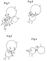
- the invention is based on a preferred Embodiment in connection with the drawing described. Show here:
- Fig. 1 shows a winding roll 1, the final diameter has reached, so to speak, almost finished winding has been.
- the winding roll lies on a contact roller 2, over which a material web 3, for example a paper web is fed.
- the web of material 3 lies here at an angle of approximately 90 ° on the contact roller 2.
- the contact roller 2 is a carrier roller of a double carrier roller winder, the second support roller 4 only dashed shown and in the remaining figures for the sake of Clarity has been omitted.
- the contact roller 2 can also by a backup roller Backing roll winder be formed.
- an adhesive tape dispenser occurs 5 in action, which is transverse to that through an arrow 6 running direction of the material web 3 two adhesive strips 7, 8 on the surface of the material web 3 applies that is not in contact with the contact roller 2, but in contact with the circumference when winding further the winding roll 3 would come.
- the tape dispenser 5 can also be arranged at another location be, for example closer to the winding roll 1. He is but shown at the position shown to the Not to impair clarity.
- the adhesive strips 7, 8 are exaggerated for better visibility shown in thick.
- a knife 9 is mounted on arms 10 which are about the axis of rotation 11 of the contact roller 2 are pivotable. This allows the knife to move in the direction of the arrow 12 move over the peripheral surface of the contact roller 2.
- the arms 10 are provided with a radial drive 13, with its help the radial position of the knife 9 can be changed.
- the knife 9 can therefore of the position shown in Fig. 1, in which there is a relative large radial distance from the surface of the contact roller 2, are shifted to the contact roller 2, as shown for example in FIG. 2 is.
- the knife 9 has a width that is larger than that Width of the rear adhesive strip 7 in the running direction. It points at least on the one adjacent to the material web 3 Surface of a coating made of polytetrafluoroethylene (PTFE) or Teflon.
- PTFE polytetrafluoroethylene
- Teflon Teflon
- the knife is placed over the rear adhesive strip in the direction of travel 7 pivoted and then onto the material web 3 lowered.
- the knife 9 is practically on the surface of the material web 3 lowered (the thickness of the adhesive strips 7, 8 is exaggerated for the sake of clarity ) Shown.
- the adhesive strip 7 through this movement and the pressure of the knife on the Surface of the material web 3 pressed so that the adhesive strip 7 an intimate connection with the material web 3 is received.
- the winding roll 1 can then by no longer shown Aids are expelled. Here will the material web 3 using the knife 9 on the contact roller 2 held.
- the knife 9 is moved radially outwards and lifts off the adhesive strip 7. Then it will be as can be seen in Fig. 4, in its starting position pivoted back.
- the Adhesive strip 7 in contact with the surface of the winding sleeve 15 and thus causes an initial glue.
- the winding process can then for the new winding roll be started. If the new winding roll theirs has reached the desired diameter, the roll change cycle begins from the front, i.e. there will be two adhesive strips 7, 8 applied and the rear adhesive strip 7 is covered by knife 9 when passing through the nip.
Landscapes
- Replacement Of Web Rolls (AREA)
Abstract
Description
Claims (10)
- Verfahren zum Aufwickeln einer Materialbahn zu einer Wickelrolle, die an einer Kontaktwalze anliegt, bei dem die Materialbahn bei Erreichen eines vorbestimmten Rollendurchmessers mit einem Messer durchtrennt wird, das durch den Nip zwischen Kontaktwalze und Wickelrolle geführt wird und das Ende der Materialbahn an der Wickelrolle festgeklebt wird, dadurch gekennzeichnet, daß mindestens zwei Klebestreifen auf die Materialbahn aufgebracht werden, bevor sich die Materialbahn an die Wickelrolle anlegt, von denen der in Laufrichtung hintere beim Durchlaufen des Nips vom Messer abgedeckt wird.
- Verfahren nach Anspruch 1, dadurch gekennzeichnet, daß das Messer radial auf dem Klebestreifen zu und nach dem Durchtrennen der Materialbahn mit einer radialen Bewegungskomponente vom Klebestreifen wegbewegt wird.
- Verfahren nach Anspruch 1 oder 2, dadurch gekennzeichnet, daß das Messer die Materialbahn festhält, bis die Wickelrolle ausgestoßen und eine neue Wikkelhülse in eine Wickelstellung gebracht worden ist.
- Verfahren nach Anspruch 3, dadurch gekennzeichnet, daß die Wickelhülse den Anfang der Materialbahn klemmend hält, während das Messer wieder in seine Ausgangsstellung gebracht wird.
- Verfahren nach einem der Ansprüche 1 bis 4, dadurch gekennzeichnet, daß man einen Klebestreifen verwendet, von dem sich das Messer gut lösen läßt.
- Wickelvorrichtung mit einer Kontaktwalze, über die eine Materialbahn zu einer Wickelrolle läuft und einem Messer, das gemeinsam mit der Materialbahn durch einen Nip zwischen der Wickelrolle und der Kontaktwalze bewegbar ist, wie mit einer Klebestreifenspenderanordnung, dadurch gekennzeichnet, daß die Klebestreifenspenderanordnung (5) mindestens zwei Klebestreifen (7, 8) ausgibt, die in Laufrichtung (6) der Materialbahn (3) hintereinander angeordnet sind, und das Messer (9) mindestens so breit wie der in Laufrichtung letzte Klebestreifen (7) ist und diesen beim Durchlaufen des Nips (14) abdeckt.
- Vorrichtung nach Anspruch 6, dadurch gekennzeichnet, daß das Messer (9) einen Radialantrieb (13) aufweist.
- Vorrichtung nach Anspruch 6 oder 7, dadurch gekennzeichnet, daß das Messer (9) verklebungshemmend oder -lösend ausgebildet ist.
- Vorrichtung nach Anspruch 8, dadurch gekennzeichnet, daß das Messer (9) eine Oberflächenbeschichtung aus Polytetrafluoräthylen aufweist.
- Vorrichtung nach einem der Ansprüche 6 bis 9, dadurch gekennzeichnet, daß der Klebestreifenspender (5) ein doppelseitiges Klebeband ausgibt.
Applications Claiming Priority (2)
| Application Number | Priority Date | Filing Date | Title |
|---|---|---|---|
| DE10030582 | 2000-06-21 | ||
| DE10030582A DE10030582C1 (de) | 2000-06-21 | 2000-06-21 | Verfahren zum Aufwickeln einer Materialbahn und Wickelvorrichtung |
Publications (3)
| Publication Number | Publication Date |
|---|---|
| EP1167257A2 true EP1167257A2 (de) | 2002-01-02 |
| EP1167257A3 EP1167257A3 (de) | 2003-09-03 |
| EP1167257B1 EP1167257B1 (de) | 2004-11-03 |
Family
ID=7646513
Family Applications (1)
| Application Number | Title | Priority Date | Filing Date |
|---|---|---|---|
| EP01113453A Expired - Lifetime EP1167257B1 (de) | 2000-06-21 | 2001-06-02 | Verfahren zum Aufwickeln einer Materialbahn und Wickelvorrichtung |
Country Status (2)
| Country | Link |
|---|---|
| EP (1) | EP1167257B1 (de) |
| DE (2) | DE10030582C1 (de) |
Cited By (4)
| Publication number | Priority date | Publication date | Assignee | Title |
|---|---|---|---|---|
| DE10206575A1 (de) * | 2002-02-18 | 2003-08-21 | Voith Paper Patent Gmbh | Verfahren zum Überführen einer laufenden Materialbahn auf einen Wickelkern und Wickelmaschine |
| DE10206576A1 (de) * | 2002-02-18 | 2003-08-28 | Voith Paper Patent Gmbh | Mittel zum Überführen einer laufenden Materialbahn auf einen Wickelkern sowie Verfahren zu seiner Verwendung |
| WO2006037450A1 (de) * | 2004-10-05 | 2006-04-13 | Windmöller & Hölscher Kg | Schneid- und transportvorrichtung für materialbahnen |
| EP1652803A3 (de) * | 2004-10-29 | 2007-11-07 | Voith Patent GmbH | Wickelmaschine |
Families Citing this family (3)
| Publication number | Priority date | Publication date | Assignee | Title |
|---|---|---|---|---|
| DE10201410A1 (de) * | 2002-01-15 | 2003-08-28 | Voith Paper Patent Gmbh | Verfahren zum Überführen einer laufenden Materialbahn auf einen neuen Wickelkern sowie Vorrichtung zur Durchführung des Verfahrens |
| DE10309049A1 (de) * | 2003-03-01 | 2004-09-09 | Voith Paper Patent Gmbh | Verfahren und Vorrichtung zum Überführen einer Materialbahn |
| FI120443B (fi) * | 2006-02-02 | 2009-10-30 | Metso Paper Inc | Menetelmä kuiturainakoneen kiinnirullaimen yhteydessä |
Citations (5)
| Publication number | Priority date | Publication date | Assignee | Title |
|---|---|---|---|---|
| US3918654A (en) * | 1973-07-21 | 1975-11-11 | Rca Corp | Automatic winding apparatus for a strip of material |
| US5092533A (en) * | 1990-10-15 | 1992-03-03 | Beloit Corporation | Method for effecting a set change in a winder |
| US5222679A (en) * | 1990-02-07 | 1993-06-29 | Jagenberg Aktiengesellschaft | Method of and apparatus for automatic replacement of a fully wound roll by a new sleeve in a winding machine |
| EP0716997A2 (de) * | 1994-12-13 | 1996-06-19 | Valmet Corporation | Verfahren und Anordnung zum Schneiden einer Bahn |
| EP0754640A2 (de) * | 1993-08-24 | 1997-01-22 | Beloit Technologies, Inc. | Wickelmaschine zum Wickeln von Bahnen |
Family Cites Families (3)
| Publication number | Priority date | Publication date | Assignee | Title |
|---|---|---|---|---|
| DE2909736C3 (de) * | 1979-03-13 | 1982-02-18 | J.M. Voith Gmbh, 7920 Heidenheim | Verfahren und Doppeltragwalzenroller zum Aufrollen von endlos zugeführten Bahnen |
| DE29610199U1 (de) * | 1996-06-13 | 1997-10-16 | Beloit Technologies Inc | Querschneidevorrichtung für Wickelmaschinen |
| DE29710225U1 (de) * | 1997-06-13 | 1998-10-22 | Beloit Technologies Inc | Bahneinführanordnung für eine Wickelmaschine |
-
2000
- 2000-06-21 DE DE10030582A patent/DE10030582C1/de not_active Expired - Fee Related
-
2001
- 2001-06-02 EP EP01113453A patent/EP1167257B1/de not_active Expired - Lifetime
- 2001-06-02 DE DE50104358T patent/DE50104358D1/de not_active Expired - Fee Related
Patent Citations (5)
| Publication number | Priority date | Publication date | Assignee | Title |
|---|---|---|---|---|
| US3918654A (en) * | 1973-07-21 | 1975-11-11 | Rca Corp | Automatic winding apparatus for a strip of material |
| US5222679A (en) * | 1990-02-07 | 1993-06-29 | Jagenberg Aktiengesellschaft | Method of and apparatus for automatic replacement of a fully wound roll by a new sleeve in a winding machine |
| US5092533A (en) * | 1990-10-15 | 1992-03-03 | Beloit Corporation | Method for effecting a set change in a winder |
| EP0754640A2 (de) * | 1993-08-24 | 1997-01-22 | Beloit Technologies, Inc. | Wickelmaschine zum Wickeln von Bahnen |
| EP0716997A2 (de) * | 1994-12-13 | 1996-06-19 | Valmet Corporation | Verfahren und Anordnung zum Schneiden einer Bahn |
Cited By (4)
| Publication number | Priority date | Publication date | Assignee | Title |
|---|---|---|---|---|
| DE10206575A1 (de) * | 2002-02-18 | 2003-08-21 | Voith Paper Patent Gmbh | Verfahren zum Überführen einer laufenden Materialbahn auf einen Wickelkern und Wickelmaschine |
| DE10206576A1 (de) * | 2002-02-18 | 2003-08-28 | Voith Paper Patent Gmbh | Mittel zum Überführen einer laufenden Materialbahn auf einen Wickelkern sowie Verfahren zu seiner Verwendung |
| WO2006037450A1 (de) * | 2004-10-05 | 2006-04-13 | Windmöller & Hölscher Kg | Schneid- und transportvorrichtung für materialbahnen |
| EP1652803A3 (de) * | 2004-10-29 | 2007-11-07 | Voith Patent GmbH | Wickelmaschine |
Also Published As
| Publication number | Publication date |
|---|---|
| DE10030582C1 (de) | 2002-01-10 |
| EP1167257B1 (de) | 2004-11-03 |
| DE50104358D1 (de) | 2004-12-09 |
| EP1167257A3 (de) | 2003-09-03 |
Similar Documents
| Publication | Publication Date | Title |
|---|---|---|
| EP0450312B1 (de) | Verfahren zum Verbinden des Bahnanfanges eines Wickels an einer Splice-Stelle mit dem Bahnende einer von einem anderen Wickel ablaufenden Bahn | |
| DE2652411C2 (de) | ||
| DE4033900C2 (de) | Splice-Stelle am Bahnanfang eines Wickels zum Verbinden des Bahnanfangs mit dem Bahnende eines anderen Wickels | |
| DE2853033A1 (de) | Vorrichtung zum herstellen von folien- kraftfahrzeugschildern | |
| EP1167257B1 (de) | Verfahren zum Aufwickeln einer Materialbahn und Wickelvorrichtung | |
| DE10118362B4 (de) | Verfahren zur Verbindung eines Bahnanfanges einer Materialrolle | |
| WO1999006313A1 (de) | Wickelverfahren, bahntrennvorrichtung und bahnwickler | |
| DE2911268C2 (de) | Vorrichtung zum ununterbrochenen Abwickeln von Warenbahnen | |
| EP0934895B1 (de) | Verfahren zum Überleiten einer Materialbahn von einer Wickelrolle auf eine Wickelhülse und Wickelvorrichtung | |
| EP1818298B1 (de) | Verfahren und Vorrichtung zum Wickeln von Teilmaterialbahnen auf Rollenkerne zu Teilmaterialbahnrollen | |
| DE4026144A1 (de) | Verfahren zum herstellen eines kontinuums von aufklebern | |
| DE10105748A1 (de) | Etikettenrolle, und Verfahren zur Bearbeitung einer solchen | |
| DE10200440B4 (de) | Verfahren zum Aufwickeln einer mit einem druckempfindlichen Klebstoff beschichteten flächigen Bahn | |
| DE10122105A1 (de) | Wickel aus streifen- oder bandförmigen Medien mit einer Identifikationskennzeichnung sowie Verfahren zur Herstellung | |
| DE2209764A1 (de) | Laminate, insbesondere mehrschichtige klebefolie, und verfahren zur herstellung | |
| WO2020070335A1 (de) | Mehrlagiges funktionsprodukt mit entfernbarer schichttrennung | |
| EP1733983B1 (de) | Verfahren zum Erzeugen einer Klebestelle an einer Wickelrolle und Vorrichtung zum Aufwickeln einer Materialbahn zu einer Wickelrolle | |
| DE10351877B4 (de) | Schneidvorrichtung zum Abtrennen von Etiketten, Verfahren zum Abtrennen von Etiketten und Druckvorrichtung | |
| DE2365807A1 (de) | Vorrichtung zum verbinden von bahnen selbsthaftenden etikettenmaterials | |
| DE19753870A1 (de) | Verfahren und Vorrichtung zum Verbinden des Endes einer ersten Materialbahn mit dem Anfang einer zweiten Materialbahn | |
| DE102021115984A1 (de) | Vorrichtung und Verfahren der Tabak verarbeitenden Industrie zum Verbinden zweier Materialbahnen | |
| DE102007032401A1 (de) | Schlauchbildungseinrichtung zum Bilden eines Schlauches aus zumindest einer Materialbahn | |
| EP1151946B1 (de) | Verfahren zum Aufwickeln einer Materialbahn und Wickelvorrichtung | |
| DE19901026A1 (de) | Verfahren und Vorrichtung zum Verbinden von Materialbahnen | |
| EP3616897A1 (de) | Verfahren zum einführen einer materialbahn in eine riffelvorrichtung |
Legal Events
| Date | Code | Title | Description |
|---|---|---|---|
| PUAI | Public reference made under article 153(3) epc to a published international application that has entered the european phase |
Free format text: ORIGINAL CODE: 0009012 |
|
| AK | Designated contracting states |
Kind code of ref document: A2 Designated state(s): AT BE CH CY DE DK ES FI FR GB GR IE IT LI LU MC NL PT SE TR |
|
| AX | Request for extension of the european patent |
Free format text: AL;LT;LV;MK;RO;SI |
|
| PUAL | Search report despatched |
Free format text: ORIGINAL CODE: 0009013 |
|
| AK | Designated contracting states |
Kind code of ref document: A3 Designated state(s): AT BE CH CY DE DK ES FI FR GB GR IE IT LI LU MC NL PT SE TR |
|
| AX | Request for extension of the european patent |
Extension state: AL LT LV MK RO SI |
|
| 17P | Request for examination filed |
Effective date: 20030731 |
|
| 17Q | First examination report despatched |
Effective date: 20031024 |
|
| GRAP | Despatch of communication of intention to grant a patent |
Free format text: ORIGINAL CODE: EPIDOSNIGR1 |
|
| AKX | Designation fees paid |
Designated state(s): DE FI |
|
| GRAS | Grant fee paid |
Free format text: ORIGINAL CODE: EPIDOSNIGR3 |
|
| GRAA | (expected) grant |
Free format text: ORIGINAL CODE: 0009210 |
|
| AK | Designated contracting states |
Kind code of ref document: B1 Designated state(s): DE FI |
|
| REF | Corresponds to: |
Ref document number: 50104358 Country of ref document: DE Date of ref document: 20041209 Kind code of ref document: P |
|
| REG | Reference to a national code |
Ref country code: IE Ref legal event code: FG4D Free format text: GERMAN |
|
| PGFP | Annual fee paid to national office [announced via postgrant information from national office to epo] |
Ref country code: DE Payment date: 20050613 Year of fee payment: 5 |
|
| PGFP | Annual fee paid to national office [announced via postgrant information from national office to epo] |
Ref country code: FI Payment date: 20050616 Year of fee payment: 5 |
|
| REG | Reference to a national code |
Ref country code: IE Ref legal event code: FD4D |
|
| PLBE | No opposition filed within time limit |
Free format text: ORIGINAL CODE: 0009261 |
|
| STAA | Information on the status of an ep patent application or granted ep patent |
Free format text: STATUS: NO OPPOSITION FILED WITHIN TIME LIMIT |
|
| 26N | No opposition filed |
Effective date: 20050804 |
|
| PG25 | Lapsed in a contracting state [announced via postgrant information from national office to epo] |
Ref country code: FI Free format text: LAPSE BECAUSE OF NON-PAYMENT OF DUE FEES Effective date: 20060602 |
|
| PG25 | Lapsed in a contracting state [announced via postgrant information from national office to epo] |
Ref country code: DE Free format text: LAPSE BECAUSE OF NON-PAYMENT OF DUE FEES Effective date: 20070103 |