EP1166855B1 - Catalyseur pour purifier de gaz d'échappement - Google Patents
Catalyseur pour purifier de gaz d'échappement Download PDFInfo
- Publication number
- EP1166855B1 EP1166855B1 EP01114935A EP01114935A EP1166855B1 EP 1166855 B1 EP1166855 B1 EP 1166855B1 EP 01114935 A EP01114935 A EP 01114935A EP 01114935 A EP01114935 A EP 01114935A EP 1166855 B1 EP1166855 B1 EP 1166855B1
- Authority
- EP
- European Patent Office
- Prior art keywords
- oxide
- catalyst
- zirconium
- cerium
- lanthanum
- Prior art date
- Legal status (The legal status is an assumption and is not a legal conclusion. Google has not performed a legal analysis and makes no representation as to the accuracy of the status listed.)
- Expired - Lifetime
Links
Images

Classifications
-
- B—PERFORMING OPERATIONS; TRANSPORTING
- B01—PHYSICAL OR CHEMICAL PROCESSES OR APPARATUS IN GENERAL
- B01D—SEPARATION
- B01D53/00—Separation of gases or vapours; Recovering vapours of volatile solvents from gases; Chemical or biological purification of waste gases, e.g. engine exhaust gases, smoke, fumes, flue gases, aerosols
- B01D53/34—Chemical or biological purification of waste gases
- B01D53/92—Chemical or biological purification of waste gases of engine exhaust gases
- B01D53/94—Chemical or biological purification of waste gases of engine exhaust gases by catalytic processes
- B01D53/9445—Simultaneously removing carbon monoxide, hydrocarbons or nitrogen oxides making use of three-way catalysts [TWC] or four-way-catalysts [FWC]
- B01D53/945—Simultaneously removing carbon monoxide, hydrocarbons or nitrogen oxides making use of three-way catalysts [TWC] or four-way-catalysts [FWC] characterised by a specific catalyst
-
- B—PERFORMING OPERATIONS; TRANSPORTING
- B01—PHYSICAL OR CHEMICAL PROCESSES OR APPARATUS IN GENERAL
- B01D—SEPARATION
- B01D53/00—Separation of gases or vapours; Recovering vapours of volatile solvents from gases; Chemical or biological purification of waste gases, e.g. engine exhaust gases, smoke, fumes, flue gases, aerosols
- B01D53/34—Chemical or biological purification of waste gases
- B01D53/92—Chemical or biological purification of waste gases of engine exhaust gases
- B01D53/94—Chemical or biological purification of waste gases of engine exhaust gases by catalytic processes
-
- B—PERFORMING OPERATIONS; TRANSPORTING
- B01—PHYSICAL OR CHEMICAL PROCESSES OR APPARATUS IN GENERAL
- B01J—CHEMICAL OR PHYSICAL PROCESSES, e.g. CATALYSIS OR COLLOID CHEMISTRY; THEIR RELEVANT APPARATUS
- B01J21/00—Catalysts comprising the elements, oxides, or hydroxides of magnesium, boron, aluminium, carbon, silicon, titanium, zirconium, or hafnium
- B01J21/06—Silicon, titanium, zirconium or hafnium; Oxides or hydroxides thereof
-
- B—PERFORMING OPERATIONS; TRANSPORTING
- B01—PHYSICAL OR CHEMICAL PROCESSES OR APPARATUS IN GENERAL
- B01J—CHEMICAL OR PHYSICAL PROCESSES, e.g. CATALYSIS OR COLLOID CHEMISTRY; THEIR RELEVANT APPARATUS
- B01J23/00—Catalysts comprising metals or metal oxides or hydroxides, not provided for in group B01J21/00
- B01J23/38—Catalysts comprising metals or metal oxides or hydroxides, not provided for in group B01J21/00 of noble metals
- B01J23/54—Catalysts comprising metals or metal oxides or hydroxides, not provided for in group B01J21/00 of noble metals combined with metals, oxides or hydroxides provided for in groups B01J23/02 - B01J23/36
- B01J23/56—Platinum group metals
- B01J23/58—Platinum group metals with alkali- or alkaline earth metals
-
- B—PERFORMING OPERATIONS; TRANSPORTING
- B01—PHYSICAL OR CHEMICAL PROCESSES OR APPARATUS IN GENERAL
- B01J—CHEMICAL OR PHYSICAL PROCESSES, e.g. CATALYSIS OR COLLOID CHEMISTRY; THEIR RELEVANT APPARATUS
- B01J23/00—Catalysts comprising metals or metal oxides or hydroxides, not provided for in group B01J21/00
- B01J23/38—Catalysts comprising metals or metal oxides or hydroxides, not provided for in group B01J21/00 of noble metals
- B01J23/54—Catalysts comprising metals or metal oxides or hydroxides, not provided for in group B01J21/00 of noble metals combined with metals, oxides or hydroxides provided for in groups B01J23/02 - B01J23/36
- B01J23/56—Platinum group metals
- B01J23/63—Platinum group metals with rare earths or actinides
-
- Y—GENERAL TAGGING OF NEW TECHNOLOGICAL DEVELOPMENTS; GENERAL TAGGING OF CROSS-SECTIONAL TECHNOLOGIES SPANNING OVER SEVERAL SECTIONS OF THE IPC; TECHNICAL SUBJECTS COVERED BY FORMER USPC CROSS-REFERENCE ART COLLECTIONS [XRACs] AND DIGESTS
- Y02—TECHNOLOGIES OR APPLICATIONS FOR MITIGATION OR ADAPTATION AGAINST CLIMATE CHANGE
- Y02T—CLIMATE CHANGE MITIGATION TECHNOLOGIES RELATED TO TRANSPORTATION
- Y02T10/00—Road transport of goods or passengers
- Y02T10/10—Internal combustion engine [ICE] based vehicles
- Y02T10/12—Improving ICE efficiencies
Definitions
- This invention relates to an exhaust gas purifying catalyst for simultaneous removal of carbon monoxide (CO), hydrocarbon (HC), and nitrogen oxides (NO x ), which are harmful component contained in the exhaust gas from an internal combustion engine, and a method for the purification of exhaust gases by the use of the catalyst.
- CO carbon monoxide
- HC hydrocarbon
- NO x nitrogen oxides
- This invention has developed a catalyst having higher heat resistant property by using oxygen storage materials having a higher heat resistant property as described below and a method for purifying exhaust gases by the use of this catalyst.
- the catalyst uses, as the oxygen storage material, a composite oxide with a homogenous tetragonal crystal structure of zirconium oxide, which is produced by doping cerium oxide and lanthanum oxide into zirconium oxide without forming independent cerium oxide or the like.
- this composite oxide manifests higher oxygen storage ability at temperatures in the range of 400°C to 500°C, even after treatments at temperatures exceeding 900°C in air, than the conventional oxygen storage materials.
- the object of this invention is accomplished by an exhaust gas purifying catalyst according to claim 1.
- the object of this invention is also accomplished by a method for simultaneously purifying carbon monoxide, hydrocarbon, and nitrogen oxide contained in the exhaust gas emitted from an internal combustion engine, particularly a gasoline engine, by the use of the catalyst mentioned above.
- the catalyst of this invention excels in heat resistant property and durability because it comprises zirconium oxide containing cerium and lanthanum.
- Example of the noble metal to be used in this invention may include at least one member selected from the group consisting of palladium, platinum, rhodium and a mixture thereof.
- the form of the noble metal is not restricted but only required to have catalytic activity.
- the amount of the noble metal to be used may comprise from 0.05 to 30 g, preferably from 0.15 to 20 g, per liter of a refractory three-dimensional structure. If this amount drops below 0.05 g, the shortage will be at a disadvantage in manifesting no sufficient catalytic activity. Conversely, if the amount exceeds 30 g, the excess will be at a disadvantage in bringing no proportionate addition to the catalytic activity.
- the amount of such catalyst component as a noble metal to be used per liter of the structure is expressed based on the apparent volume of the molded structure itself when the catalyst component itself is molded or based on the apparent volume of the structure when catalyst components are deposited.
- the refractory inorganic oxide may be any of the substances, which are generally used as a catalyst carrier.
- examples of such substances may include ⁇ -alumina, ⁇ , ⁇ , ⁇ , ⁇ or like active alumina, titania, composite oxides of zirconia, titania, silica, or the like, such as alumina-titania, alumina-zirconia, titania-zirconia, and the like.
- the active alumina is used particularly advantageously.
- the amount of the refractory inorganic oxide to be used may comprise from 10 to 300 g, preferably from 50 to 250 g, per liter of the structure. If this amount drops below 10 g, the shortage will be at a disadvantage in not enabling the noble metal to be sufficiently dispersed and preventing the produced catalyst from acquiring sufficient durability. Conversely, if this amount exceeds 300 g, the excess will be at a disadvantage in adding to the pressure loss of the exhaust gas.
- the zirconium oxide containing cerium and lanthanum used in this invention exhibits a tetragonal crystal structure of zirconium oxide by X-ray diffraction pattern.
- the oxide used in this invention shows only the peak of the tetragonal zirconium oxide, while the conventional zirconium oxide containing cerium and lanthanum shows peaks of various independent oxides including cerium oxide.
- the oxide of this invention shows only a tetragonal crystal structure.
- the weight ratio of cerium to zirconium, i.e. cerium as CeO 2 : zirconium as ZrO 2 is in the range of 1 : 8 to 1 : 1, preferably 1 : 5 to 1 : 1 and (b) the weight ratio of lanthanum to zirconium, i.e. lanthanum as La 2 O 3 : zirconium as ZrO 2 , is in the range of 1 : 1.5 to 1 : 60, preferably 1 : 1.5 to 1 : 40.
- the method for producing the zirconium oxide containing cerium and lanthanum may include the following two kinds of method. The method, however, may deviate from such typical methods without departure from the spirit of this invention.
- the amount of noble metal may comprise from 0.05 to 30 g, that of cerium as reduced to CeO 2 from 10 to 100 g, that of zirconium as ZrO 2 from 10 to 100 g, that of lanthanum as La 2 O 3 from 0.1 to 50 g, and that of refractory inorganic oxide from 10 to 300 g per liter of the structure, respectively.
- the respective amounts of cerium, lanthanum, and zirconium are those of the relevant elements that are included in the amount of the zirconium oxide containing cerium and lanthanum.
- an alkaline earth metal oxide in the amount generally in the range of 0.1 to 50 g, preferably 1 to 30 g, per liter of the structure. If this amount drops below 0.1 g, the shortage will be at a disadvantage in that the catalyst containing Pd manifests only insufficient heat resistant property. Conversely, if the amount exceeds 50 g, it will be at a disadvantage in not bringing any additional performance proportionate to the excess.
- the amount of the zirconium oxide containing cerium and lanthanum to be used may comprise from 5 to 250 g, preferably from 10 to 200 g, per liter of the structure. If this amount drops below 5 g, the shortage will be at a disadvantage in that the catalyst suffers deficiency in durability and OSC (Oxygen Storage Component) capacity. Conversely, if the amount exceeds 250 g, the excess will be at a disadvantage in increasing the pressure loss of the exhaust gas.
- the catalyst containing Pd as the noble metal preferably contains an alkaline earth metal oxide, besides the catalyst components mentioned above, from the viewpoint of durability and the ability to purify NO x .
- the alkaline earth metal oxide may include the oxides of barium, magnesium calcium, and strontium. According to claim 1, the catalyst comprises barium oxide.
- the amount of a noble metal may comprise from 0.05 to 30 g, that of cerium as reduced to CeO 2 from 10 to 100 g, that of zirconium as ZrO 2 from 10 to 100 g, that of lanthanum as La 2 O 3 from 0.1 to 50 g, that of a refractory inorganic oxide from 10 to 300 g, and that of an alkaline earth metal oxide from 0.1 to 50 g per liter of the structure, respectively.
- the respective amounts of cerium, lanthanum, and zirconium are those of the relevant elements that are included in the amount of the zirconium oxide containing cerium and lanthanum.
- the refractory three-dimensional structure that is coated with the catalyst components mentioned above may be a honeycomb carrier, preferably an integrally molded honeycomb structure.
- Examples of this structure may include a monolithic honeycomb carrier, a metal honeycomb carrier, and a plug honeycomb carrier.
- the monolithic honeycomb may be a honeycomb carrier.
- honeycomb carriers using cordierite, mullite, ⁇ -alumina, zirconia, titania, titanium phosphate, aluminum titanate, betallite, spondumene, aluminosilicate, and magnesium silicate are commendable.
- those of cordierite quality prove particularly preferable.
- integrally molded structures using such oxidation proof heat resistant metals, as stainless steel and Fe-Cr-Al alloy are usable.
- Such a monolithic carrier is produced by methods of extrusion molding or winding a sheet like element into a tight roll.
- the cell shape for gas passage may be a hexagon, tetragon, triangle, or corrugation, whichever fits the occasion best.
- the carrier is usable satisfactorily when the cell density (the number of cells per unit cross sectional area, 6.45 cm 2 (1 square inch )) may comprise from 100 to 1500 cells, preferably from 200 to 900 cells.
- Impregnation method is generally used favorably.
- the catalyst according to this invention can be prepared by the following method, for example.
- the preparation is effected by first placing the powders of a refractory inorganic oxide such as alumina and the zirconium oxide containing cerium and lanthanum in the aqueous solution of a prescribed amount of the nitrate, for example, of a noble metal such as platinum, thoroughly mixing them together till impregnation of the powder components with the solution, then drying the product of impregnation at a temperature of 80°C to 250°C, preferably of 100°C to 150°C, and subsequently calcining the dried weight at a temperature of 300°C to 850°C, preferably of 400°C to 700°C, for a period of 0.5 to 5 hours, preferably of 1 to 2 hours.
- Pd is contained as the noble metal
- an alkaline earth metal oxide Such an alkaline earth metal oxide or the salts thereof, like nitrate or acetate, are added at this stage. Where all the oxides are used except for the noble metal, the process may omit the drying and calcining steps and proceed directly to the subsequent wet pulverizing step.
- the produced powder is wet pulverized into slurry using a ball mill.
- the structure made of cordierite is impregnated with the resultant slurry of a catalytic composition, drained to expel excess slurry, then dried at a temperature of 80°C to 250°C, preferably of 100°C to 150°C, and optionally calcined at a temperature of 300°C to 850°C, preferably of 400°C to 700°C, for a period of 0.5 to 3 hours, preferably of 1 to 2 hours.
- the amount of the catalytic active component to be deposited may comprise from 30 to 400 g per liter of the catalyst.
- Preparing slurries of one same or different composition as described above and impregnating the structure with the slurries may produce a multi-layer coat. It is further permissible to effect the impregnation afterward as with the aqueous solution of the salt of a noble metal.
- the catalyst of this invention excels in the ability to purify simultaneously carbon monoxide, hydrocarbon, and nitrogen oxide, which are contained in the exhaust gas emitted from an internal combustion engine, particularly a gasoline engine.
- the catalyst is preferably mounted in an exhaust pipe near the engine from the viewpoint of hydrocarbon oxidation.
- Fig. 1 shows the spectrum pattern, produced by the X-ray diffraction, of the zirconium oxide containing cerium and lanthanum in this invention
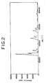
- Fig. 2 the spectrum pattern of the conventional zirconium oxide containing cerium and lanthanum.
- the conventional oxide revealed the peaks of various independent oxides including cerium oxide.
- the oxide used in Example 1 revealed only a peak of the tetragonal crystal structure of zirconium oxide.
- Other oxides of the present invention also reveal same results as in Fig. 1 . Such oxides were evaluated after each the samples had been aged in air at 1000°C for 10 hours.
- a zirconium-cerium-lanthanum composite oxide (Powder A1) was obtained by hydrolyzing a zirconium oxychloride solution thereby obtaining zirconium hydroxide, adding an aqueous nitric acid solution of cerium and lanthanum to the zirconium hydroxide and mixing them together, neutralizing the resultant mixture by addition of an alkali, washing, drying at 120°C for two hours and calcining at 700°C for one hour the product of neutralization, with the relevant components used in amounts calculated to form a weight ratio of 40 g of zirconium oxide, 20 g of cerium oxide, and 15 g of lanthanum oxide.
- Powder A1 A quantity of 40 g of Powder A1 was impregnated with an aqueous palladium nitrate solution containing 2 g of palladium. Thereafter, the impregnated composite oxide was dried thoroughly at 150°C and then calcined at 500°C for one hour to obtain a palladium-containing zirconium-cerium-lanthanum composite oxide (Powder B1).
- alumina ⁇ -Al 2 O 3 having a specific surface area of 150 m 2 /g was impregnated with an aqueous palladium nitrate solution containing 2 g of palladium, dried thoroughly at 150°C, and then calcined at 500°C for one hour to obtain palladium-containing alumina.
- a monolithic carrier made of cordierite (available from NGK Insulators Ltd. in Japan: cell density 400 cells/6.45 cm 2 (1 square inch), outside diameter 33 mm x 76 mm in length) was impregnated with the resultant slurry, removed from the slurry, blown with compressed air to expel excess slurry, then dried at 150°C for two hours, and calcined at 500°C for one hour to obtain catalyst 1.
- a zirconium-cerium-lanthanum composite oxide (Powder A2) was obtained according to the procedure of Example 1 while changing the amounts of zirconium oxychloride, cerium, and lanthanum to be used so as to form a weight ratio of 25 g of zirconium oxide, 12.5 g of cerium oxide, and 9.5 g of lanthanum oxide.
- a palladium-containing zirconium-cerium-lanthanum composite oxide (Powder B3) was obtained by impregnating 47 g of Powder A1 with an aqueous palladium nitrate solution containing 2 g of palladium as in Example 1.
- Powder A1 was prepared as in Example 1. Next, a palladium-containing zirconium-cerium-lanthanum composite oxide (Powder B3) was obtained as in Example 3.
- a zirconium-cerium-lanthanum composite oxide (Powder A5) was prepared according to the procedure of Example 1 while changing the amounts of zirconium oxychloride, cerium, and lanthanum to be used so as to form a weight ratio of 40 g of zirconium oxide, 10 g of cerium oxide, and 10 g of lanthanum oxide.
- Powder A5 A quantity of 47 g Powder A5 was impregnated with an aqueous palladium nitrate solution containing 2 g of palladium to obtain a palladium-containing zirconium-cerium-lanthanum composite oxide (Powder B5) as in Example 1.
- Powders A5 and B5 were prepared as in Example 5.
- the produced slurry was coated to the Pd catalyst coat (C6) to obtain catalyst 6.
- a catalyst 7 was obtained according to the procedure of Example 6 while using, instead of 10.2 g of the rhodium-containing alumina, 10.4 g of platinum rhodium containing alumina obtained as in Example 3 by impregnating 10 g of alumina ( ⁇ -Al 2 O 3 ) having a specific surface area of 150 m 2 /g with an aqueous rhodium nitrate solution containing 0.2 g of rhodium and an aqueous platinum nitrate solution containing 0.2 g of platinum.
- Catalysts were prepared according to the procedures of Examples 1 to 7, respectively, while, in the preparation of zirconium-cerium-lanthanum composite oxide, using the zirconium hydroxide obtained by hydrolyzing zirconium oxychloride having zirconium as a raw material having no tetragonal crystal structure of zirconium oxide instead of a corresponding amount of zirconium oxide.
- Fig. 2 shows crystal patterns other than the tetragonal crystal structure and is based on the material as in Comparative Example 1.
- Catalysts were prepared according to the procedures of Examples 1 and 3, respectively, while using, instead of the zirconium-cerium-lanthanum composite oxide, the zirconium-cerium composite oxide obtained by adding an aqueous cerium nitrate solution to zirconium oxide so as to form a weight ratio of 40 g of zirconium oxide and 20 g of cerium oxide, mixing them together, drying, and calcining the resultant mixture. These composite oxides also showed crystal patterns other than the tetragonal crystal structure as shown in Fig. 2 .
- a catalyst was prepared according to the procedure of Example 7 while using, instead of the zirconium-cerium-lanthanum composite oxide, the zirconium-cerium composite oxide obtained by adding an aqueous cerium nitrate solution to zirconium oxide so as to form a weight ratio of 25 g of zirconium oxide and 12.5 g of cerium oxide, mixing them together, drying, and calcining the resultant mixture.
- the composite oxide also showed crystal patterns other than the tetragonal crystal structure as shown in Fig. 2 . TABLE 2 Ex.
- Amount of noble metal g/L
- Amount of ZrO 2 /CeO 2 /La 2 O 3 g/L
- BaO g/L
- Pd Pt Rh ZrO 2 CeO 2 La 2 O 3 1 4 0 0 40 20 15 30 2 2 0 0 25 12.5 9.5 10 3 2 0 0.2 40 20 15 10 4 2 0 0.2 40 20 15 10 5 2 0 0.2 40 10 10 10 6 2 0.3 0.2 40 20 15 10 7 0 0.1 0.2 25 12.5 9.5 0
- Com. Com.
- the catalysts obtained contained such amounts of catalyst components as shown in Table 1 per liter of structure.
- a commercially available electronically controlled engine was used.
- a multiple converter packed with given catalysts was set in the exhaust system of the engine to test the catalyst for durability.
- the engine was operated in the mode of 60 seconds of stationary operation and 6 seconds of deceleration (during which period the fuel was cut and the catalyst was exposed to the high-temperature oxidation atmosphere) and the catalyst was left standing under the condition causing the temperature of the catalyst bed to remain at 900°C for 50 hours during the stationary operation.
- the catalyst was rated for performance by using the engine and setting, in the exhaust system of the engine, the multiple converters.
- the three-way performance of the catalyst was rated under the condition of 400°C of catalyst inlet and 250,000 hr -1 of spatial velocity.
- the average air-fuel ratio was continuously varied by fluctuating the air-fuel ratio (A/F) within ⁇ 1.0 A/F at 1 Hz by dint of a 1 Hz sine wave signal introduced from an external oscillator into the control unit of the engine.
- the inlet and outlet gas compositions of the catalyst were simultaneously analyzed to determine the purification ratios of CO, HC, and NO x during the change of the average air-fuel ratio, A/F, from 15.1 to 14.1.
- Table 3 shows the purification ratios at the crossover points of CO and NO x and the purification ratios of HC for the A/F values at the points.
- the purification of the catalyst at low temperatures was rated by operating the engine with the air-fuel ratio fluctuated within ⁇ 0.5 A/F (1 Hz) by the oscillation of the gas to fix the average air-fuel ratio, A/F, at 14.6, setting a heat exchanger in front of the catalyst converter in the engine exhaust system, varying the catalyst inlet gas temperature from 200°C to 500°C at a fixed temperature increasing rate (20°C/min), and analyzing the catalyst inlet and outlet gas compositions thereby determining the purification ratios of CO, HC, and NO x .
- the temperature at which the purification ratio of CO, HC, and NO x reached 50% (light off temperature) was measured, respectively, and shown in Table 3.
- NO x was analyzed with a chemical emission spectral analyzer (CLD) and the hydrocarbon with a hydrogen flame ionizing analyzer (NDIR) respectively.
- CLD chemical emission spectral analyzer
- NDIR hydrogen flame ionizing analyzer
- the catalyst of this invention was capable of simultaneously and efficiently removing the three components, CO, HC, and NO x . It is also noted that this catalyst was improved in heat resistant property as compared with the conventional catalyst.
Claims (2)
- Catalyseur pour purifier du gaz d'échappement possédant une structure tridimensionnelle réfractaire revêtue d'un composant catalytiquement actif comprenant au moins un type de métaux nobles, un oxyde inorganique réfractaire, et un oxyde de zirconium contenant du cérium et du lanthane, caractérisé par le fait que la structure cristalline de l'oxyde de zirconium contenant du cérium et du lanthane est une structure tétragonale d'oxyde de zirconium, où le catalyseur comprend de plus de l'oxyde de baryum.
- Procédé pour la purification simultanée du monoxyde de carbone, de l'hydrocarbure, et de l'oxyde d'azote contenus dans le gaz d'échappement provenant d'un moteur à combustion interne en utilisant le catalyseur présenté dans la revendication 1.
Applications Claiming Priority (2)
| Application Number | Priority Date | Filing Date | Title |
|---|---|---|---|
| JP2000192934 | 2000-06-27 | ||
| JP2000192934 | 2000-06-27 |
Publications (2)
| Publication Number | Publication Date |
|---|---|
| EP1166855A1 EP1166855A1 (fr) | 2002-01-02 |
| EP1166855B1 true EP1166855B1 (fr) | 2009-06-17 |
Family
ID=18692004
Family Applications (1)
| Application Number | Title | Priority Date | Filing Date |
|---|---|---|---|
| EP01114935A Expired - Lifetime EP1166855B1 (fr) | 2000-06-27 | 2001-06-20 | Catalyseur pour purifier de gaz d'échappement |
Country Status (5)
| Country | Link |
|---|---|
| US (1) | US6602479B2 (fr) |
| EP (1) | EP1166855B1 (fr) |
| KR (1) | KR100532195B1 (fr) |
| CA (1) | CA2351754C (fr) |
| DE (1) | DE60138984D1 (fr) |
Families Citing this family (23)
| Publication number | Priority date | Publication date | Assignee | Title |
|---|---|---|---|---|
| EP1199096A1 (fr) * | 2000-10-21 | 2002-04-24 | Degussa AG | Catalyseur pour la destruction des emissions de CO, VOC et composés organiques halogenes |
| JP3845274B2 (ja) * | 2001-06-26 | 2006-11-15 | ダイハツ工業株式会社 | 排ガス浄化用触媒 |
| JP2005517625A (ja) * | 2002-02-15 | 2005-06-16 | ナノフェイズ テクノロジーズ コーポレイション | 複合ナノ粒子物質およびその製造方法 |
| JP3758601B2 (ja) | 2002-05-15 | 2006-03-22 | トヨタ自動車株式会社 | 吸蔵還元型NOx浄化用触媒 |
| JP2004041867A (ja) * | 2002-07-09 | 2004-02-12 | Daihatsu Motor Co Ltd | 排ガス浄化用触媒 |
| AU2003281203A1 (en) * | 2002-07-09 | 2004-01-23 | Cataler Corporation | Catalyst for clarifying exhaust gas |
| JP2004041868A (ja) * | 2002-07-09 | 2004-02-12 | Daihatsu Motor Co Ltd | 排ガス浄化用触媒 |
| JP4311918B2 (ja) * | 2002-07-09 | 2009-08-12 | ダイハツ工業株式会社 | ペロブスカイト型複合酸化物の製造方法 |
| JP2005066482A (ja) * | 2003-08-25 | 2005-03-17 | Toyota Motor Corp | 排ガス浄化用触媒とその低温浄化能の評価方法 |
| US7238640B2 (en) * | 2003-12-30 | 2007-07-03 | Ford Global Technologies, Llc | Minimization of purge NOx release from NOx traps by optimizing the oxygen storage capacity |
| EP1736241B1 (fr) | 2004-03-11 | 2012-10-03 | Cataler Corporation | Catalyseur de clarification des gaz d chappement |
| CN101484240B (zh) * | 2006-07-06 | 2012-10-24 | 卡塔勒公司 | 储氧材料 |
| DE102007063064A1 (de) * | 2007-12-21 | 2009-06-25 | Aloys Wobben | Verfahren zur Vermeidung und/oder zum Verringern von Schadstoffanteilen im Abgas einer Verbrennungsmaschine |
| US8771624B2 (en) * | 2008-03-19 | 2014-07-08 | Umicore Shokubai Japan Co., Ltd | Catalyst for purifying exhaust gas from internal combustion engine and process for purifying exhaust gas using the same |
| JP5526502B2 (ja) * | 2008-07-16 | 2014-06-18 | 日産自動車株式会社 | 排気ガス浄化用触媒及びその製造方法 |
| US8568675B2 (en) | 2009-02-20 | 2013-10-29 | Basf Corporation | Palladium-supported catalyst composites |
| EP2457657A4 (fr) * | 2009-07-24 | 2017-03-08 | Cataler Corporation | Catalyseur de purification de gaz d échappement |
| DE202011110610U1 (de) * | 2010-02-01 | 2015-07-02 | Johnson Matthey Public Limited Company | Extrudiertes SCR-Filter |
| WO2012012894A1 (fr) * | 2010-07-26 | 2012-02-02 | Syngraffi Corporation | Système, procédé et programme d'ordinateur pour permettre une signature et une dédicace d'objets d'information |
| US9266092B2 (en) | 2013-01-24 | 2016-02-23 | Basf Corporation | Automotive catalyst composites having a two-metal layer |
| JP5816648B2 (ja) * | 2013-04-18 | 2015-11-18 | 三井金属鉱業株式会社 | 排気ガス浄化用触媒組成物及び排気ガス浄化用触媒 |
| CN104056626B (zh) * | 2014-07-22 | 2016-11-02 | 中自环保科技股份有限公司 | 一种贵金属催化剂制备方法 |
| US11666889B2 (en) * | 2018-02-15 | 2023-06-06 | Sumitomo Chemical Company, Limited | Inorganic oxide |
Family Cites Families (8)
| Publication number | Priority date | Publication date | Assignee | Title |
|---|---|---|---|---|
| AU595655B2 (en) | 1986-11-04 | 1990-04-05 | Kabushiki Kaisha Toyota Chuo Kenkyusho | Catalyst for the purification of exhaust gas |
| US5015617A (en) | 1988-04-14 | 1991-05-14 | Nippon Shokubai Kagaku Kogyo Co., Ltd. | Catalyst for purifying exhaust gas and method for production thereof |
| US5254519A (en) * | 1990-02-22 | 1993-10-19 | Engelhard Corporation | Catalyst composition containing platinum and rhodium components |
| US5057483A (en) | 1990-02-22 | 1991-10-15 | Engelhard Corporation | Catalyst composition containing segregated platinum and rhodium components |
| US5116800A (en) * | 1990-12-11 | 1992-05-26 | Allied-Signal Inc. | High durability and exhuast catalyst with low hydrogen sulfide emissions |
| JPH0760117A (ja) | 1993-08-30 | 1995-03-07 | Honda Motor Co Ltd | 排気ガス浄化用触媒 |
| WO1997030777A1 (fr) | 1996-02-21 | 1997-08-28 | Asec Manufacturing Company | Support en composite d'oxydes metalliques destine aux catalyseurs de conversion des gaz d'echappement |
| JP4053623B2 (ja) * | 1996-12-27 | 2008-02-27 | 阿南化成株式会社 | ジルコニウム−セリウム系複合酸化物及びその製造方法 |
-
2001
- 2001-06-20 US US09/885,503 patent/US6602479B2/en not_active Expired - Lifetime
- 2001-06-20 DE DE60138984T patent/DE60138984D1/de not_active Expired - Lifetime
- 2001-06-20 EP EP01114935A patent/EP1166855B1/fr not_active Expired - Lifetime
- 2001-06-26 KR KR10-2001-0036780A patent/KR100532195B1/ko active IP Right Grant
- 2001-06-26 CA CA002351754A patent/CA2351754C/fr not_active Expired - Fee Related
Also Published As
| Publication number | Publication date |
|---|---|
| EP1166855A1 (fr) | 2002-01-02 |
| CA2351754C (fr) | 2007-07-24 |
| KR100532195B1 (ko) | 2005-11-29 |
| KR20020001616A (ko) | 2002-01-09 |
| US20020015674A1 (en) | 2002-02-07 |
| CA2351754A1 (fr) | 2001-12-27 |
| DE60138984D1 (de) | 2009-07-30 |
| US6602479B2 (en) | 2003-08-05 |
Similar Documents
| Publication | Publication Date | Title |
|---|---|---|
| EP1166855B1 (fr) | Catalyseur pour purifier de gaz d'échappement | |
| EP1834694B1 (fr) | Catalyseur de purification de gaz d'échappement, procédé de production associé, et procédé de purification de gaz d'échappement utilisant le catalyseur | |
| EP2104567B1 (fr) | Procédé de préparation d'un matériau de stockage de NOx | |
| KR100567726B1 (ko) | 배기가스 정화용 촉매 | |
| EP0507590B1 (fr) | Catalyseur pour la purification des effluents gazeux | |
| EP0152052B1 (fr) | Procédé de production d'un catalyseur monolytique pour l'épuration des gaz d'échappement | |
| US20020131914A1 (en) | Catalyst composition | |
| US20090286680A1 (en) | Exhaust Gas Purification Catalyst and Exhaust Gas Purification Catalyst Member | |
| JP3235640B2 (ja) | 内燃機関排ガス浄化用触媒 | |
| KR19990076641A (ko) | 엔진 배기 가스 처리 장치 및 사용 방법 | |
| EP2343121B1 (fr) | Catalyseur de purification des gaz d'échappement et méthode de purification l'utilisant | |
| EP0993861B1 (fr) | Catalyseur pour la purification de gaz d'échappement de moteurs à combustion pauvre | |
| JP3494147B2 (ja) | 排ガス浄化用触媒とその製造方法及び排ガス浄化方法 | |
| US9339793B2 (en) | Catalyst composition for exhaust gas cleaning and catalyst for automobile exhaust gas cleaning | |
| WO2013065421A1 (fr) | Catalyseur de purification de gaz d'échappement | |
| JP3817443B2 (ja) | 排気ガス浄化用触媒 | |
| JP2578219B2 (ja) | 排ガス浄化用触媒の製造方法 | |
| JP3264697B2 (ja) | 排気ガス浄化用触媒およびこれを用いてなる浄化システム | |
| CA2740472C (fr) | Catalyseur de purification de gaz d'echappement et procede de purification d'un gaz d'echappement a l'aide du catalyseur | |
| JP4749608B2 (ja) | 排気ガス浄化用触媒 | |
| JPH05277373A (ja) | 排気ガス浄化用触媒およびこれを用いてなる浄化システム | |
| US20230271164A1 (en) | Ce-Zr COMPOSITE OXIDE AND EXHAUST GAS PURIFICATION CATALYST USING SAME | |
| JPH05168927A (ja) | 排気ガス浄化用触媒およびこれを用いてなる浄化システム | |
| JP3264696B2 (ja) | 排気ガス浄化用触媒およびこれを用いてなる浄化システム | |
| JPS63190643A (ja) | 排気ガス浄化用触媒 |
Legal Events
| Date | Code | Title | Description |
|---|---|---|---|
| PUAI | Public reference made under article 153(3) epc to a published international application that has entered the european phase |
Free format text: ORIGINAL CODE: 0009012 |
|
| AK | Designated contracting states |
Kind code of ref document: A1 Designated state(s): AT BE CH CY DE DK ES FI FR GB GR IE IT LI LU MC NL PT SE TR Kind code of ref document: A1 Designated state(s): DE FR GB IT |
|
| AX | Request for extension of the european patent |
Free format text: AL;LT;LV;MK;RO;SI |
|
| 17P | Request for examination filed |
Effective date: 20020104 |
|
| AKX | Designation fees paid |
Free format text: DE FR GB IT |
|
| 17Q | First examination report despatched |
Effective date: 20050224 |
|
| RAP1 | Party data changed (applicant data changed or rights of an application transferred) |
Owner name: INTERNATIONAL CATALYST TECHNOLOGY, INC. Owner name: ICT CO., LTD. |
|
| GRAP | Despatch of communication of intention to grant a patent |
Free format text: ORIGINAL CODE: EPIDOSNIGR1 |
|
| GRAS | Grant fee paid |
Free format text: ORIGINAL CODE: EPIDOSNIGR3 |
|
| GRAA | (expected) grant |
Free format text: ORIGINAL CODE: 0009210 |
|
| AK | Designated contracting states |
Kind code of ref document: B1 Designated state(s): DE FR GB IT |
|
| REG | Reference to a national code |
Ref country code: GB Ref legal event code: FG4D |
|
| REF | Corresponds to: |
Ref document number: 60138984 Country of ref document: DE Date of ref document: 20090730 Kind code of ref document: P |
|
| PLBE | No opposition filed within time limit |
Free format text: ORIGINAL CODE: 0009261 |
|
| STAA | Information on the status of an ep patent application or granted ep patent |
Free format text: STATUS: NO OPPOSITION FILED WITHIN TIME LIMIT |
|
| 26N | No opposition filed |
Effective date: 20100318 |
|
| REG | Reference to a national code |
Ref country code: DE Ref legal event code: R082 Ref document number: 60138984 Country of ref document: DE Representative=s name: MAI DOERR BESIER PATENTANWAELTE, DE |
|
| REG | Reference to a national code |
Ref country code: DE Ref legal event code: R082 Ref document number: 60138984 Country of ref document: DE Representative=s name: MAI DOERR BESIER PATENTANWAELTE, DE |
|
| REG | Reference to a national code |
Ref country code: DE Ref legal event code: R081 Ref document number: 60138984 Country of ref document: DE Owner name: INTERNATIONAL CATALYST TECHNOLOGY, INC., US Free format text: FORMER OWNER: ICT CO. LTD., INTERNATIONAL CATALYST TECHNOLO, , US Effective date: 20130204 Ref country code: DE Ref legal event code: R082 Ref document number: 60138984 Country of ref document: DE Representative=s name: MAI DOERR BESIER PATENTANWAELTE, DE Effective date: 20130204 Ref country code: DE Ref legal event code: R082 Ref document number: 60138984 Country of ref document: DE Representative=s name: MAI DOERR BESIER PATENTANWAELTE, DE Effective date: 20120502 Ref country code: DE Ref legal event code: R081 Ref document number: 60138984 Country of ref document: DE Owner name: UMICORE SHOKUBAI JAPAN CO., LTD., JP Free format text: FORMER OWNER: ICT CO. LTD., INTERNATIONAL CATALYST TECHNOLO, , US Effective date: 20130204 Ref country code: DE Ref legal event code: R081 Ref document number: 60138984 Country of ref document: DE Owner name: UMICORE SHOKUBAI USA INC., US Free format text: FORMER OWNER: ICT CO. LTD., INTERNATIONAL CATALYST TECHNOLO, , US Effective date: 20130204 Ref country code: DE Ref legal event code: R081 Ref document number: 60138984 Country of ref document: DE Owner name: UMICORE SHOKUBAI USA INC., AUBURN HILLS, US Free format text: FORMER OWNER: ICT CO. LTD., INTERNATIONAL CATALYST TECHNOLO, , US Effective date: 20130204 Ref country code: DE Ref legal event code: R081 Ref document number: 60138984 Country of ref document: DE Owner name: UMICORE SHOKUBAI USA INC., AUBURN HILLS, US Free format text: FORMER OWNERS: ICT CO. LTD., OSAKA, JP; INTERNATIONAL CATALYST TECHNOLOGY, INC., AUBURN HILLS, MICH., US Effective date: 20130204 Ref country code: DE Ref legal event code: R081 Ref document number: 60138984 Country of ref document: DE Owner name: UMICORE SHOKUBAI JAPAN CO., LTD., JP Free format text: FORMER OWNERS: ICT CO. LTD., OSAKA, JP; INTERNATIONAL CATALYST TECHNOLOGY, INC., AUBURN HILLS, MICH., US Effective date: 20130204 Ref country code: DE Ref legal event code: R082 Ref document number: 60138984 Country of ref document: DE Representative=s name: MAI DOERR BESIER EUROPEAN PATENT ATTORNEYS - E, DE Effective date: 20130204 Ref country code: DE Ref legal event code: R082 Ref document number: 60138984 Country of ref document: DE Representative=s name: MAI DOERR BESIER EUROPEAN PATENT ATTORNEYS - E, DE Effective date: 20120502 |
|
| REG | Reference to a national code |
Ref country code: DE Ref legal event code: R082 Ref document number: 60138984 Country of ref document: DE Representative=s name: MAI DOERR BESIER PATENTANWAELTE, DE |
|
| REG | Reference to a national code |
Ref country code: GB Ref legal event code: 732E Free format text: REGISTERED BETWEEN 20130711 AND 20130717 |
|
| REG | Reference to a national code |
Ref country code: FR Ref legal event code: TQ Owner name: UMICORE SHOKUBAI USA INC., US Effective date: 20130709 Ref country code: FR Ref legal event code: CD Owner name: UMICORE SHOKUBAI USA INC., US Effective date: 20130709 Ref country code: FR Ref legal event code: TQ Owner name: INTERNATIONAL CATALYST TECHNOLOGY, INC., US Effective date: 20130709 Ref country code: FR Ref legal event code: CA Effective date: 20130709 Ref country code: FR Ref legal event code: CD Owner name: INTERNATIONAL CATALYST TECHNOLOGY, INC., US Effective date: 20130709 |
|
| REG | Reference to a national code |
Ref country code: DE Ref legal event code: R082 Ref document number: 60138984 Country of ref document: DE Representative=s name: MAI DOERR BESIER PATENTANWAELTE, DE Effective date: 20130626 Ref country code: DE Ref legal event code: R081 Ref document number: 60138984 Country of ref document: DE Owner name: UMICORE SHOKUBAI JAPAN CO., LTD., JP Free format text: FORMER OWNER: INTERNATIONAL CATALYST TECHNOLO, UMICORE SHOKUBAI JAPAN CO., LTD, , JP Effective date: 20130626 Ref country code: DE Ref legal event code: R081 Ref document number: 60138984 Country of ref document: DE Owner name: UMICORE SHOKUBAI USA INC., US Free format text: FORMER OWNER: INTERNATIONAL CATALYST TECHNOLO, UMICORE SHOKUBAI JAPAN CO., LTD, , JP Effective date: 20130626 Ref country code: DE Ref legal event code: R081 Ref document number: 60138984 Country of ref document: DE Owner name: UMICORE SHOKUBAI USA INC., AUBURN HILLS, US Free format text: FORMER OWNER: INTERNATIONAL CATALYST TECHNOLO, UMICORE SHOKUBAI JAPAN CO., LTD, , JP Effective date: 20130626 Ref country code: DE Ref legal event code: R081 Ref document number: 60138984 Country of ref document: DE Owner name: UMICORE SHOKUBAI USA INC., AUBURN HILLS, US Free format text: FORMER OWNERS: INTERNATIONAL CATALYST TECHNOLOGY, INC., AUBURN HILLS, MICH., US; UMICORE SHOKUBAI JAPAN CO., LTD., MINATO, TOKYO, JP Effective date: 20130626 Ref country code: DE Ref legal event code: R081 Ref document number: 60138984 Country of ref document: DE Owner name: UMICORE SHOKUBAI JAPAN CO., LTD., JP Free format text: FORMER OWNERS: INTERNATIONAL CATALYST TECHNOLOGY, INC., AUBURN HILLS, MICH., US; UMICORE SHOKUBAI JAPAN CO., LTD., MINATO, TOKYO, JP Effective date: 20130626 Ref country code: DE Ref legal event code: R082 Ref document number: 60138984 Country of ref document: DE Representative=s name: MAI DOERR BESIER EUROPEAN PATENT ATTORNEYS - E, DE Effective date: 20130626 |
|
| REG | Reference to a national code |
Ref country code: FR Ref legal event code: RM Effective date: 20140120 |
|
| REG | Reference to a national code |
Ref country code: FR Ref legal event code: PLFP Year of fee payment: 16 |
|
| REG | Reference to a national code |
Ref country code: FR Ref legal event code: PLFP Year of fee payment: 17 |
|
| REG | Reference to a national code |
Ref country code: FR Ref legal event code: PLFP Year of fee payment: 18 |
|
| PGFP | Annual fee paid to national office [announced via postgrant information from national office to epo] |
Ref country code: DE Payment date: 20180625 Year of fee payment: 18 |
|
| PGFP | Annual fee paid to national office [announced via postgrant information from national office to epo] |
Ref country code: FR Payment date: 20180625 Year of fee payment: 18 |
|
| PGFP | Annual fee paid to national office [announced via postgrant information from national office to epo] |
Ref country code: GB Payment date: 20180626 Year of fee payment: 18 Ref country code: IT Payment date: 20180622 Year of fee payment: 18 |
|
| REG | Reference to a national code |
Ref country code: DE Ref legal event code: R119 Ref document number: 60138984 Country of ref document: DE |
|
| GBPC | Gb: european patent ceased through non-payment of renewal fee |
Effective date: 20190620 |
|
| PG25 | Lapsed in a contracting state [announced via postgrant information from national office to epo] |
Ref country code: IT Free format text: LAPSE BECAUSE OF NON-PAYMENT OF DUE FEES Effective date: 20190620 Ref country code: DE Free format text: LAPSE BECAUSE OF NON-PAYMENT OF DUE FEES Effective date: 20200101 Ref country code: GB Free format text: LAPSE BECAUSE OF NON-PAYMENT OF DUE FEES Effective date: 20190620 |
|
| PG25 | Lapsed in a contracting state [announced via postgrant information from national office to epo] |
Ref country code: FR Free format text: LAPSE BECAUSE OF NON-PAYMENT OF DUE FEES Effective date: 20190630 |
|
| P01 | Opt-out of the competence of the unified patent court (upc) registered |
Effective date: 20230602 |