EP1166680A1 - Kasten - Google Patents
Kasten Download PDFInfo
- Publication number
- EP1166680A1 EP1166680A1 EP01111481A EP01111481A EP1166680A1 EP 1166680 A1 EP1166680 A1 EP 1166680A1 EP 01111481 A EP01111481 A EP 01111481A EP 01111481 A EP01111481 A EP 01111481A EP 1166680 A1 EP1166680 A1 EP 1166680A1
- Authority
- EP
- European Patent Office
- Prior art keywords
- railing
- box according
- groove
- box
- front panel
- Prior art date
- Legal status (The legal status is an assumption and is not a legal conclusion. Google has not performed a legal analysis and makes no representation as to the accuracy of the status listed.)
- Granted
Links
Images


Classifications
-
- A—HUMAN NECESSITIES
- A47—FURNITURE; DOMESTIC ARTICLES OR APPLIANCES; COFFEE MILLS; SPICE MILLS; SUCTION CLEANERS IN GENERAL
- A47B—TABLES; DESKS; OFFICE FURNITURE; CABINETS; DRAWERS; GENERAL DETAILS OF FURNITURE
- A47B88/00—Drawers for tables, cabinets or like furniture; Guides for drawers
- A47B88/90—Constructional details of drawers
- A47B88/969—Drawers having means for organising or sorting the content
-
- A—HUMAN NECESSITIES
- A47—FURNITURE; DOMESTIC ARTICLES OR APPLIANCES; COFFEE MILLS; SPICE MILLS; SUCTION CLEANERS IN GENERAL
- A47B—TABLES; DESKS; OFFICE FURNITURE; CABINETS; DRAWERS; GENERAL DETAILS OF FURNITURE
- A47B88/00—Drawers for tables, cabinets or like furniture; Guides for drawers
- A47B88/90—Constructional details of drawers
- A47B88/919—Accessories or additional elements for drawers, e.g. drawer lighting
- A47B88/931—Rails or rods mounted above the drawer walls, e.g. for stabilisation of the drawer or for suspension of the content
-
- A—HUMAN NECESSITIES
- A47—FURNITURE; DOMESTIC ARTICLES OR APPLIANCES; COFFEE MILLS; SPICE MILLS; SUCTION CLEANERS IN GENERAL
- A47B—TABLES; DESKS; OFFICE FURNITURE; CABINETS; DRAWERS; GENERAL DETAILS OF FURNITURE
- A47B2210/00—General construction of drawers, guides and guide devices
- A47B2210/02—Drawers with hollow lateral walls in two parts
-
- A—HUMAN NECESSITIES
- A47—FURNITURE; DOMESTIC ARTICLES OR APPLIANCES; COFFEE MILLS; SPICE MILLS; SUCTION CLEANERS IN GENERAL
- A47B—TABLES; DESKS; OFFICE FURNITURE; CABINETS; DRAWERS; GENERAL DETAILS OF FURNITURE
- A47B88/00—Drawers for tables, cabinets or like furniture; Guides for drawers
- A47B88/90—Constructional details of drawers
- A47B88/919—Accessories or additional elements for drawers, e.g. drawer lighting
- A47B88/931—Rails or rods mounted above the drawer walls, e.g. for stabilisation of the drawer or for suspension of the content
- A47B88/938—Means for connecting rails or rods to drawers
Definitions
- the present invention relates to a box according to the preamble of the claim 1.
- a box is designed in particular as a drawer on both sides is mounted on a pull-out guide of a piece of furniture.
- a drawer with a support rail is known, which on all sides is arranged above the walls of the drawer. Between two neighboring ones Rail struts are slidably arranged on the sides of the railing. For this are Clamping caps are provided which encompass the pentagonal rail profile.
- the disadvantage of this drawer is that only relatively poor components on the Railing can be attached.
- the pentagonal shape leaves no insertion or Inserting further components, for example a subdivision system.
- drawers are known from AT 399086 B, which are in the side area are provided with circular railings. These railings are mounted on a holding part, with which a front panel setting is possible. This type of railing too is not very suitable for attaching other components.
- the railing should on the one hand Leadership and / or can be used to attach a subdivision system.
- the groove has a cross section a tapered neck section. This enables the insertion of Components in the manner of a snap connection. Furthermore, the neck portion for Guide components that engage mushroom-shaped in the groove and along the Railing can be moved.
- the groove has one substantially rectangular interior opening on one long side to the outside is. This enables particularly good longitudinal guidance along the railing guarantee. If there are lead-in chamfers on the neck section, leave the connecting means insert more easily into the groove.
- the front panel is on one Holding part of the wall elements fixed and the position of the front panel to the wall elements adjustable.
- An adjustment block can be attached to the holding part for the adjustment be stored, which is biased by a screw to the front panel. Since the Adjustment block is held on the railing and in a pin in a recess engages the bottom of the groove, the railing also serves to stabilize the Drawer. In this case, inclinations of the front panel can be done in a simple manner of the adjustment block can be compensated.
- the subdivision system can be by means of a clamp piece be fixed, which encompasses the railing and, for example, by means of a Protrusion engages in the groove in order to support the clamp piece in a rotationally fixed manner.
- An easy one subdivision system to be manufactured that requires only a few components, is obtained when a rail is pushed onto the clamp piece, which is vertical is aligned with the railing of the wall element and on the floor or one other wall element is supported.
- the railing profiles of the subdivision system be identical to those of the box.
- the clip piece is for a particularly stable fixation of the subdivision system locked by means of a reinforcing part inserted into the groove.
- the reinforcement part can be mounted on the groove of the subdivision system and by means of Engage the pin in the groove of the railing of the wall element.
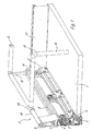
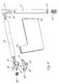
- the fasteners 4 include an attachment 5 on which a side profile 7 and an upper cover profile 8 are mounted are. A profile can also be mounted on the inside.
- the side profile 7 and the cover profile 8 are connected to the attachment 5 via suitable snap-in connections. Pins 6 are formed on the foremost attachment 5, which are for receiving serve a front panel (not shown).
- a holding part 9 is mounted, on the top of which a railing 10 is arranged.
- the rail 10 runs parallel to the cover profile 8 and is connected to a further rail 12 in the rear area via a corner connector.
- a rear wall 13 At the back of the box is provided with a rear wall 13, which with the rearmost fastener 4 is connected.
- the opposite wall element 2 and the front panel are not shown in Fig. 1 for a better overview.
- the beginning of a subdivision system is indicated within the box, whereby a railing 14 by means of a corner connector 15 and one led to the floor 1 Railing 16 is supported.
- the railing 14 is on the railing via a clamp piece 46 10 held.
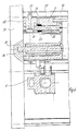
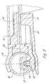
- the holding element 9 is via two screws 24 which pass through openings 23 are guided in the cover profile 8, attached. Grab the screws 24 in the holding element 9, a web 30 and a T-shaped in the upper region Has guide piece 29.
- the T-shaped guide piece 29 is in a groove 25 of the Rail 10 insertable, the guide piece through the tapered neck portion of the groove 29 can not be removed from the groove 25.
- a fastening screw 34 is provided for fixing a front panel 31, which is carried out through a chamber 35 of the holding element 9 and into the front panel 31 is screwed in.
- the screw 34 can be released in order to then use an adjusting block 20 to position the Front panel 31 to change.
- a screw 32 is in the holding element 9 guided and screwed a nut 33 which is rotatably mounted in a receptacle 36 is.
- the screw 32 abuts the adjusting block 20, which is on the other side of the Front panel 31 is present. By turning the screw 32, the adjustment block is thus 20 pressed against the front panel 31 and moved relative to the holding part 9.
- Adjustment block 20 Since the Adjustment block 20 has a pin 21 which is in the bottom of the groove 25 of the railing 10 engages, the rail is at the same time an adjustment of the front panel 10 moved. As a result, there is no gap between railing 10 and front panel 31 out.
- the T-shaped guide piece 29 slides in the railing 10. Then the position can be fixed by means of the fastening screw 34.
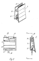
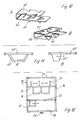
- FIG. 5A to 5C the holding part 9 is shown in detail, with FIG. 5B one Section A / A along the line in Fig. 5C.
- FIG. 5B one Section A / A along the line in Fig. 5C.
- openings 37 which serve to receive the screws 24.
- a projection 38 is provided which is inserted into the cover profile 8 for centering is.
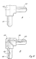
- a corner connector 11 ' is shown, the pin 26' for the Has engagement in a rail 10, which has a groove 25 corresponding to FIG. 2.
- the pins 26 'and 27' are adapted to the inner contour of the rail 10.
- the corner connector 11 ' is provided with pins 28', which are in the cover profile 8 intervene.
- a staple 46 is inserted into the railing 40 with a projection 54 and engages with it two legs, the railing 10 of the wall element 2.
- a thickening 52 is formed which engages in the neck portion of the groove 25.
- the clamp piece 46 is thus rotatably mounted on the rail 10 and can be moved to this. Through the elastic legs of the clip piece 46 this can be deducted from the railing 10.
- a reinforcing part 47 is provided, which has two pins 48 engages through openings 53 in the thickening 52, the pins 48 in engage the inner portion of the groove 25. This will pull the Clip piece 46 avoided.
- the reinforcing part 47 is by means of lateral claws 49, in the manner of a locking connection with the lower leg of the Clip piece 46 are connected, equipped. Furthermore, the reinforcing part 47 provided with a guide part 51 which engages in the groove of the railing 40. Thereby the reinforcing part cannot fall out downwards, but only along the Railing 40 can be moved.
- On the railing 40 there is also a partition plate 41 held, which is held by means of a rib 55 in the groove of the railing 40.
- the Railing 40 is over a corner piece 43, which is provided with projections 57 and 58, supported on the floor by a railing 42.
- the subdivision disk 41 is held in the railing 42 by means of a rib 56.
- the clamp piece 46 engages around the railing 10 and is locked by means of the reinforcing part 47 and the pin 48.
- a sheet metal clamp 60 is provided, which after has teeth 61 protruding on the outside and teeth 62 protruding on the inside. The tines 61 rest against the railing 40, while the inner tines 62 abut the projection 54 of the clamp piece 46. This will make the connection between bracket piece 46 and rail 40 improved.
- FIG. 11A shows a modification of the partitioning system.
- a railing 40 ' is designed as shown in FIGS. 7 and 8. At the railing 40 'is an arcuate Subdivision segment 41 'arranged in the groove of the railing 40' is mounted. The railing 40 'is on both sides of the railings 10 of the opposite one Wall elements 2 held.
- a railing 40 "is on both sides is held on a rail 10, a subdivision disk 41 "in the groove stored.
- the box can be made using the rails 10 and various standard elements can be flexibly divided into chambers. 12 is an example of such Box shown by a subdivision system into different segments is divided.
- the box is designed as a drawer and has two side wall elements 70 and 76, which are provided with a railing in the upper area.
- On a front panel 78 is mounted on the front, which is actuated by means of a button 79 can be.
- To form a box is a rear wall 77 with the side wall elements 70 and 76 connected.
- the subdivision system consists of two Relings 71 and 72, which is as shown in FIGS. 7 and 8, with the railings of Sidewall elements 70 and 76 are connected.
- Within the box are subdivision elements 73, 74, 75 provided within the groove of the railings 71 and 72 are slidably mounted. It is also possible to use the groove of the railings 71 and 72 not to be arranged downwards, but to the side.
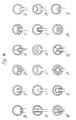
- the rail 10 includes a groove 25 having a tapered neck portion 102. In radial Inward direction, lead-in chamfers 103 are provided, which are an introduction of fasteners. Within the groove 25 is a rectangular one Recessed interior 100, which is open to the outside on a side surface. The Groove 25 is closed with a bottom 101.
- a groove 112 is formed, which has a corrugation 111 on the side walls.
- the corrugation 111 also gives a screw a good hold, if in special cases an immovable fastening of the subdivision system is desired.
- the groove 112 is with a bottom 113 provided, which protrudes in width over the insertion openings, so that an approximately triangular interior is formed.
- FIGS. 14B to 14S Further possible embodiments for the railing are shown in FIGS. 14B to 14S shown. Different clamping, locking or other fastening devices can be used be provided on the groove of the railing.
- the corner connector 120 comprises two protrusions 121 and 122, which can be inserted into the cover profiles of the box.
- latches 123 To the Protrusions 121 and 122 are formed latches 123, respectively, from the protrusions 121 and 122 stand out easily and have a certain elasticity.
Landscapes
- Connection Of Plates (AREA)
- Drawers Of Furniture (AREA)
- Rigid Containers With Two Or More Constituent Elements (AREA)
- Stackable Containers (AREA)
- Passenger Equipment (AREA)
Abstract
Description
- Fig. 1
- eine perspektivische Teilansicht eines ersten Ausführungsbeispieles eines erfindungsgemäßen Kastens;
- Fig. 2
- eine perspektivische Explosionsansicht eines Wandelementes des Kastens der Fig. 1;
- Fig. 3
- eine Vorderansicht des Wandelementes der Fig. 2;
- Fig. 4
- eine geschnittene Seitenansicht des Wandelementes der Fig. 2;
- Fig. 5A bis 5C
- mehrere Ansichten eines Halteteils des Wandelementes der Fig. 2;
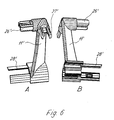
- Fig. 6A u. 6B
- mehrere Ansichten eines Eckverbinders für ein Wandelement;
- Fig. 7
- eine perspektivische Ansicht eines mit dem Kasten der Fig. 1 verbindbaren Unterteilungselementes;
- Fig. 8
- eine perspektivische Explosionsansicht des Unterteilungselementes der Fig. 7;
- Fig. 9
- eine vergrößerte Ausschnittansicht der Anbringung des Unterteilungselementes der Fig. 7;
- Fig. 10A u. 10B
- zwei Ansichten eines Klammerelementes des Unterteilungselementes;
- Fig. 11A
- eine schematische Ansicht eines Unterteilungselementes in einer modifizierten Ausführungsform;
- Fig. 11B
- eine schematische Ansicht eines Unterteilungselementes in einer modifizierten Ausführungsform;
- Fig. 12
- eine schematische Draufsicht auf einen Kasten mit einem modifizierten Unterteilungssystem;
- Fig. 13
- eine Querschnittsansicht des Relingprofils;
- Fig. 14A bis 14S
- mehrere Ansichten von alternativen Querschnittsformen für das Relingprofil, und
- Fig. 15A u. 15B
- einen modifizierten Eckverbinder für den Kasten.
Claims (16)
- Kasten, insbesondere an einer Ausziehführung gelagerter Schubkasten, mit einem Boden (1), zwei an gegenüberliegenden Seiten des Bodens (1) angeordneten Wandelementen (2) und einer Frontblende (31), wobei die Wandelemente (2) eine sich von der Frontblende (31) nach hinten erstreckende Reling (10) umfassen, dadurch gekennzeichnet, dass in der Reling (10) zur Verbindung mit weiteren Bauteilen eine Nut (25) ausgespart ist.
- Kasten nach Anspruch 1, dadurch gekennzeichnet, dass die Nut (25) im Querschnitt einen verjüngten Halsabschnitt (102) aufweist.
- Kasten nach Anspruch 1 oder 2, dadurch gekennzeichnet, dass die Nut (25) im Querschnitt einen im wesentlichen rechteckförmigen Innenraum (100) aufweist, der an einer Längsseite nach außen hin geöffnet ist.
- Kasten nach Anspruch 2 oder 3, dadurch gekennzeichnet, dass an dem Halsabschnitt (102) Einführschrägen (103) vorgesehen sind.
- Kasten nach einem der Ansprüche 1 bis 4, dadurch gekennzeichnet, dass die Frontblende (31) an einem Halteteil (9) der Wandelemente (2) fixiert ist, und die Position der Frontblende (31) zu den Wandelementen (2) verstellbar ist.
- Kasten nach Anspruch 5, dadurch gekennzeichnet, dass einem Halteteil (9) ein Justierblock (20) gelagert ist, der mittels einer Schraube (32) zu der Frontblende (31) hin vorgespannt ist.
- Kasten nach Anspruch 6, dadurch gekennzeichnet, dass der Justierblock (20) an der Reling (10) gehalten ist und mit einem Zapfen (21) in einer Aussparung in dem Boden der Nut (25) eingreift.
- Kasten nach einem der Ansprüche 1 bis 7, dadurch gekennzeichnet, dass an der Rückseite des Kastens eine Reling (12) vorgesehen ist, die mit der Reling (10) der Wandelemente (2) über einen Eckverbinder (11) miteinander verbunden sind.
- Kasten nach einem der Ansprüche 1 bis 8, dadurch gekennzeichnet, dass an mindestens einer Reling (10, 12) ein Unterteilungssystem für den Kasten angebracht ist.
- Kasten nach Anspruch 9, dadurch gekennzeichnet, dass das Unterteilungssystem ein Klammerstück (46) aufweist, das die Reling (10) umgreift.
- Kasten nach Anspruch 10, dadurch gekennzeichnet, dass das Klammerstück (46) über einen in die Nut (25) eingreifenden Vorsprung (52) drehfest gelagert ist.
- Kasten nach Anspruch 10 oder 11, dadurch gekennzeichnet, dass auf das Klammerstück (46) eine Reling (40) aufgeschoben ist, die senkrecht zu der Reling (10) des Wandelementes (2) ausgerichtet ist und am Boden (1) oder an einem anderen Wandelement (2) abgestützt ist.
- Kasten nach einem der Ansprüche 9 bis 12, dadurch gekennzeichnet, dass an der Reling (40) des Unterteilungssystems eine Unterteilungsscheibe (41, 41', 41") gehalten ist, die mit einer am Boden (1) abgestützten Reling (42) verbunden ist.
- Kasten nach einem der Ansprüche 9 bis 13, dadurch gekennzeichnet, dass das Klammerstück (46) mittels eines in die Nut (25) eingefügten Verstärkungsteils (47) arretiert ist.
- Kasten nach einem der Ansprüche 1bis 14, dadurch gekennzeichnet, dass die Reling (10, 12, 40, 40', 40", 42, 110) ein Strangpreßprofil ist.
- Kasten nach einem der Ansprüche 1bis 14, dadurch gekennzeichnet, dass die Reling (10, 12, 40, 40', 40", 42, 110) ein aus Blech geformtes Profil ist
Applications Claiming Priority (2)
| Application Number | Priority Date | Filing Date | Title |
|---|---|---|---|
| DE10032094A DE10032094A1 (de) | 2000-07-01 | 2000-07-01 | Kasten |
| DE10032094 | 2000-07-01 |
Publications (2)
| Publication Number | Publication Date |
|---|---|
| EP1166680A1 true EP1166680A1 (de) | 2002-01-02 |
| EP1166680B1 EP1166680B1 (de) | 2008-08-20 |
Family
ID=7647480
Family Applications (1)
| Application Number | Title | Priority Date | Filing Date |
|---|---|---|---|
| EP01111481A Expired - Lifetime EP1166680B1 (de) | 2000-07-01 | 2001-05-11 | Kasten |
Country Status (4)
| Country | Link |
|---|---|
| EP (1) | EP1166680B1 (de) |
| AT (1) | ATE405189T1 (de) |
| DE (2) | DE10032094A1 (de) |
| ES (1) | ES2312383T3 (de) |
Cited By (8)
| Publication number | Priority date | Publication date | Assignee | Title |
|---|---|---|---|---|
| EP1649781A3 (de) * | 2004-10-20 | 2006-12-06 | Paul Hettich GmbH & Co. KG | Rahmengestell eines Schubkastens |
| DE202008002539U1 (de) * | 2008-02-22 | 2009-07-02 | Paul Hettich Gmbh & Co. Kg | Schubkasten |
| DE202009012184U1 (de) | 2008-11-06 | 2010-02-11 | Julius Blum Gmbh | Schublade mit einem Trennelement zur Schubladenunterteilung |
| EP2250931A1 (de) * | 2009-05-12 | 2010-11-17 | Heinrich J. Kesseböhmer KG | Schrankeinrichtungsgegenstand |
| WO2011095439A1 (de) * | 2010-02-05 | 2011-08-11 | Paul Hettich Gmbh & Co. Kg | Schubkasten mit einem teilersystem |
| WO2012055157A1 (zh) * | 2010-10-27 | 2012-05-03 | 东莞世巨五金塑胶制品有限公司 | 具有隔板结构的盒体及置物盒隔板结构 |
| CN103237477A (zh) * | 2010-11-15 | 2013-08-07 | Segos株式会社 | 收纳空间分割装置 |
| AT13256U1 (de) * | 2011-04-15 | 2013-09-15 | Blum Gmbh Julius | Schublade mit einer Stützvorrichtung zum Abstützen einer Schubladenwand |
Families Citing this family (5)
| Publication number | Priority date | Publication date | Assignee | Title |
|---|---|---|---|---|
| DE102008057170B4 (de) * | 2008-11-13 | 2017-08-24 | Fackelmann Gmbh + Co Kg | Schublade und Adapterelement |
| DE202009000048U1 (de) * | 2009-01-22 | 2010-06-17 | Paul Hettich Gmbh & Co. Kg | Schrankmöbel |
| DE102011050069A1 (de) * | 2011-05-03 | 2012-11-08 | Paul Hettich Gmbh & Co. Kg | Teilersystem zur Unterteilung eines Schubkasteninnenraumes und Schubkasten |
| DE202014105348U1 (de) * | 2014-11-07 | 2016-02-10 | Grass Gmbh | Wandbauteil sowie Schublade und Möbel |
| DE202015101989U1 (de) * | 2015-04-22 | 2016-07-25 | Grass Gmbh | Vorrichtung zur Anbringung einer Quer- und/oder Längsreling an einer Zarge einer Möbel-Schublade |
Citations (5)
| Publication number | Priority date | Publication date | Assignee | Title |
|---|---|---|---|---|
| DE9004924U1 (de) * | 1989-05-10 | 1990-07-19 | Julius Blum Ges.m.b.H., Höchst | Schublade mit vorzugsweise metallischen Schubladenzargen |
| DE9201801U1 (de) | 1992-02-13 | 1992-04-02 | Paul Hettich GmbH & Co, 4983 Kirchlengern | Schubkasten mit einer Stützreling |
| AT399084B (de) | 1988-12-09 | 1995-03-27 | Brown & Williamson Tobacco Corp | Zigarette |
| US5466061A (en) * | 1993-09-11 | 1995-11-14 | Mepla-Werke Lautenschlager Gmbh & Co. Kg | Corner connecting hardware for drawers |
| DE19510119A1 (de) * | 1995-03-21 | 1996-09-26 | Lautenschlaeger Mepla Werke | Schnellmontage-Befestigungsbeschlag für Schubladen-Frontblenden |
-
2000
- 2000-07-01 DE DE10032094A patent/DE10032094A1/de not_active Ceased
-
2001
- 2001-05-11 ES ES01111481T patent/ES2312383T3/es not_active Expired - Lifetime
- 2001-05-11 AT AT01111481T patent/ATE405189T1/de active
- 2001-05-11 EP EP01111481A patent/EP1166680B1/de not_active Expired - Lifetime
- 2001-05-11 DE DE50114234T patent/DE50114234D1/de not_active Expired - Lifetime
Patent Citations (5)
| Publication number | Priority date | Publication date | Assignee | Title |
|---|---|---|---|---|
| AT399084B (de) | 1988-12-09 | 1995-03-27 | Brown & Williamson Tobacco Corp | Zigarette |
| DE9004924U1 (de) * | 1989-05-10 | 1990-07-19 | Julius Blum Ges.m.b.H., Höchst | Schublade mit vorzugsweise metallischen Schubladenzargen |
| DE9201801U1 (de) | 1992-02-13 | 1992-04-02 | Paul Hettich GmbH & Co, 4983 Kirchlengern | Schubkasten mit einer Stützreling |
| US5466061A (en) * | 1993-09-11 | 1995-11-14 | Mepla-Werke Lautenschlager Gmbh & Co. Kg | Corner connecting hardware for drawers |
| DE19510119A1 (de) * | 1995-03-21 | 1996-09-26 | Lautenschlaeger Mepla Werke | Schnellmontage-Befestigungsbeschlag für Schubladen-Frontblenden |
Cited By (12)
| Publication number | Priority date | Publication date | Assignee | Title |
|---|---|---|---|---|
| EP1649781A3 (de) * | 2004-10-20 | 2006-12-06 | Paul Hettich GmbH & Co. KG | Rahmengestell eines Schubkastens |
| DE202008002539U1 (de) * | 2008-02-22 | 2009-07-02 | Paul Hettich Gmbh & Co. Kg | Schubkasten |
| DE202009012184U1 (de) | 2008-11-06 | 2010-02-11 | Julius Blum Gmbh | Schublade mit einem Trennelement zur Schubladenunterteilung |
| EP2250931A1 (de) * | 2009-05-12 | 2010-11-17 | Heinrich J. Kesseböhmer KG | Schrankeinrichtungsgegenstand |
| WO2011095439A1 (de) * | 2010-02-05 | 2011-08-11 | Paul Hettich Gmbh & Co. Kg | Schubkasten mit einem teilersystem |
| CN102753056A (zh) * | 2010-02-05 | 2012-10-24 | 保罗海蒂诗有限及两合公司 | 具有分配系统的抽屉 |
| JP2013518637A (ja) * | 2010-02-05 | 2013-05-23 | ポール ヘティッヒ ゲーエムベーハー ウント ツェーオー. カーゲー | 仕切りシステムを有する引出し |
| CN102753056B (zh) * | 2010-02-05 | 2015-01-07 | 保罗海蒂诗有限及两合公司 | 具有分配系统的抽屉 |
| RU2557723C2 (ru) * | 2010-02-05 | 2015-07-27 | Пауль Хеттих Гмбх Унд Ко. Кг | Выдвижной ящик с разделительной системой |
| WO2012055157A1 (zh) * | 2010-10-27 | 2012-05-03 | 东莞世巨五金塑胶制品有限公司 | 具有隔板结构的盒体及置物盒隔板结构 |
| CN103237477A (zh) * | 2010-11-15 | 2013-08-07 | Segos株式会社 | 收纳空间分割装置 |
| AT13256U1 (de) * | 2011-04-15 | 2013-09-15 | Blum Gmbh Julius | Schublade mit einer Stützvorrichtung zum Abstützen einer Schubladenwand |
Also Published As
| Publication number | Publication date |
|---|---|
| EP1166680B1 (de) | 2008-08-20 |
| DE50114234D1 (de) | 2008-10-02 |
| ES2312383T3 (es) | 2009-03-01 |
| ATE405189T1 (de) | 2008-09-15 |
| DE10032094A1 (de) | 2002-01-10 |
Similar Documents
| Publication | Publication Date | Title |
|---|---|---|
| EP1084655B1 (de) | Befestigungsanordnung | |
| EP1084661B1 (de) | Unterteilungssystem | |
| EP3496572B1 (de) | Vorrichtung zur befestigung eines vorzugsweise flächigen gegenstandes an einem bauwerk | |
| EP3760076A1 (de) | Verbindungsstift für möbelteile | |
| EP1166680B1 (de) | Kasten | |
| EP0940067A2 (de) | Schaltschrank mit einer montageplatte | |
| DE4004891A1 (de) | Vorrichtung zum loesbaren befestigen von zweck- oder zierleisten an moebelstuecken | |
| DE4301327A1 (en) | Method of fitting a guide rail to sliding drawer - has spring catch fitted to underside of drawer which engages slot in rail and holds it in place | |
| EP1157636A1 (de) | Befestigungsanordnung | |
| DE19837367C2 (de) | Rahmenprofil für einen Schaltschrank | |
| EP0901207A1 (de) | Schaltschrank | |
| DE29907856U1 (de) | Führungsvorrichtung zur Aufnahme von Gleit- und Schiebeelementen an Möbeln | |
| DE3607754C2 (de) | Wandbefestigungselement für Flächen- und Kompaktheizkörper | |
| DE19707741A1 (de) | Möbelscharnier | |
| DE2641606C2 (de) | Wandkonstruktion für Kabinen, insbesondere für Sanitärkabinen | |
| EP0383213B1 (de) | Konsolenhalter | |
| DE20307353U1 (de) | Verbindungsbeschlag für Schubladen-Wände | |
| DE102007009667B4 (de) | Profilkonstruktion | |
| DE20000627U1 (de) | Vorrichtung zur axialfesten Fixierung von Gegenständen in einer hinterschnittenen Nut | |
| DE19620709C5 (de) | Möbelfußsystem | |
| DE69002342T2 (de) | Befestigungsvorrichtung durch Zusammenschrauben auf einem Profil, insbesondere auf einem Elektrizitätsschrank. | |
| AT393204B (de) | Moebel mit mindestens einem schubkasten | |
| DE4433660C1 (de) | Bausatz zum Nachrüsten eines Schreib- oder Arbeitstisches | |
| EP0276668B1 (de) | Schubkasten | |
| DE202023105372U1 (de) | Haltevorrichtung zur Anbringung eines Einsatzteils an einem Regalpfosten |
Legal Events
| Date | Code | Title | Description |
|---|---|---|---|
| PUAI | Public reference made under article 153(3) epc to a published international application that has entered the european phase |
Free format text: ORIGINAL CODE: 0009012 |
|
| AK | Designated contracting states |
Kind code of ref document: A1 Designated state(s): AT BE CH CY DE DK ES FI FR GB GR IE IT LI LU MC NL PT SE TR |
|
| AX | Request for extension of the european patent |
Free format text: AL;LT;LV;MK;RO;SI |
|
| 17P | Request for examination filed |
Effective date: 20020611 |
|
| AKX | Designation fees paid |
Free format text: AT BE CH CY DE DK ES FI FR GB GR IE IT LI LU MC NL PT SE TR |
|
| 17Q | First examination report despatched |
Effective date: 20031223 |
|
| APBN | Date of receipt of notice of appeal recorded |
Free format text: ORIGINAL CODE: EPIDOSNNOA2E |
|
| APBR | Date of receipt of statement of grounds of appeal recorded |
Free format text: ORIGINAL CODE: EPIDOSNNOA3E |
|
| APBX | Invitation to file observations in appeal sent |
Free format text: ORIGINAL CODE: EPIDOSNOBA2E |
|
| APBZ | Receipt of observations in appeal recorded |
Free format text: ORIGINAL CODE: EPIDOSNOBA4E |
|
| APBT | Appeal procedure closed |
Free format text: ORIGINAL CODE: EPIDOSNNOA9E |
|
| APAF | Appeal reference modified |
Free format text: ORIGINAL CODE: EPIDOSCREFNE |
|
| GRAP | Despatch of communication of intention to grant a patent |
Free format text: ORIGINAL CODE: EPIDOSNIGR1 |
|
| GRAS | Grant fee paid |
Free format text: ORIGINAL CODE: EPIDOSNIGR3 |
|
| GRAA | (expected) grant |
Free format text: ORIGINAL CODE: 0009210 |
|
| AK | Designated contracting states |
Kind code of ref document: B1 Designated state(s): AT BE CH CY DE DK ES FI FR GB GR IE IT LI LU MC NL PT SE TR |
|
| REG | Reference to a national code |
Ref country code: GB Ref legal event code: FG4D Free format text: NOT ENGLISH |
|
| REG | Reference to a national code |
Ref country code: CH Ref legal event code: EP |
|
| REG | Reference to a national code |
Ref country code: IE Ref legal event code: FG4D Free format text: LANGUAGE OF EP DOCUMENT: GERMAN |
|
| REF | Corresponds to: |
Ref document number: 50114234 Country of ref document: DE Date of ref document: 20081002 Kind code of ref document: P |
|
| PG25 | Lapsed in a contracting state [announced via postgrant information from national office to epo] |
Ref country code: FI Free format text: LAPSE BECAUSE OF FAILURE TO SUBMIT A TRANSLATION OF THE DESCRIPTION OR TO PAY THE FEE WITHIN THE PRESCRIBED TIME-LIMIT Effective date: 20080820 |
|
| REG | Reference to a national code |
Ref country code: ES Ref legal event code: FG2A Ref document number: 2312383 Country of ref document: ES Kind code of ref document: T3 |
|
| REG | Reference to a national code |
Ref country code: IE Ref legal event code: FD4D |
|
| PG25 | Lapsed in a contracting state [announced via postgrant information from national office to epo] |
Ref country code: DK Free format text: LAPSE BECAUSE OF FAILURE TO SUBMIT A TRANSLATION OF THE DESCRIPTION OR TO PAY THE FEE WITHIN THE PRESCRIBED TIME-LIMIT Effective date: 20080820 Ref country code: IE Free format text: LAPSE BECAUSE OF FAILURE TO SUBMIT A TRANSLATION OF THE DESCRIPTION OR TO PAY THE FEE WITHIN THE PRESCRIBED TIME-LIMIT Effective date: 20080820 |
|
| PG25 | Lapsed in a contracting state [announced via postgrant information from national office to epo] |
Ref country code: PT Free format text: LAPSE BECAUSE OF FAILURE TO SUBMIT A TRANSLATION OF THE DESCRIPTION OR TO PAY THE FEE WITHIN THE PRESCRIBED TIME-LIMIT Effective date: 20090120 |
|
| PLBE | No opposition filed within time limit |
Free format text: ORIGINAL CODE: 0009261 |
|
| STAA | Information on the status of an ep patent application or granted ep patent |
Free format text: STATUS: NO OPPOSITION FILED WITHIN TIME LIMIT |
|
| 26N | No opposition filed |
Effective date: 20090525 |
|
| BERE | Be: lapsed |
Owner name: PAUL HETTICH G.M.B.H. & CO. Effective date: 20090531 |
|
| PG25 | Lapsed in a contracting state [announced via postgrant information from national office to epo] |
Ref country code: MC Free format text: LAPSE BECAUSE OF NON-PAYMENT OF DUE FEES Effective date: 20090531 |
|
| REG | Reference to a national code |
Ref country code: CH Ref legal event code: PL |
|
| PG25 | Lapsed in a contracting state [announced via postgrant information from national office to epo] |
Ref country code: SE Free format text: LAPSE BECAUSE OF FAILURE TO SUBMIT A TRANSLATION OF THE DESCRIPTION OR TO PAY THE FEE WITHIN THE PRESCRIBED TIME-LIMIT Effective date: 20081120 Ref country code: CH Free format text: LAPSE BECAUSE OF NON-PAYMENT OF DUE FEES Effective date: 20090531 Ref country code: LI Free format text: LAPSE BECAUSE OF NON-PAYMENT OF DUE FEES Effective date: 20090531 |
|
| PG25 | Lapsed in a contracting state [announced via postgrant information from national office to epo] |
Ref country code: BE Free format text: LAPSE BECAUSE OF NON-PAYMENT OF DUE FEES Effective date: 20090531 |
|
| PG25 | Lapsed in a contracting state [announced via postgrant information from national office to epo] |
Ref country code: GR Free format text: LAPSE BECAUSE OF FAILURE TO SUBMIT A TRANSLATION OF THE DESCRIPTION OR TO PAY THE FEE WITHIN THE PRESCRIBED TIME-LIMIT Effective date: 20081121 |
|
| PG25 | Lapsed in a contracting state [announced via postgrant information from national office to epo] |
Ref country code: LU Free format text: LAPSE BECAUSE OF NON-PAYMENT OF DUE FEES Effective date: 20090511 |
|
| PG25 | Lapsed in a contracting state [announced via postgrant information from national office to epo] |
Ref country code: TR Free format text: LAPSE BECAUSE OF FAILURE TO SUBMIT A TRANSLATION OF THE DESCRIPTION OR TO PAY THE FEE WITHIN THE PRESCRIBED TIME-LIMIT Effective date: 20080820 |
|
| PG25 | Lapsed in a contracting state [announced via postgrant information from national office to epo] |
Ref country code: CY Free format text: LAPSE BECAUSE OF FAILURE TO SUBMIT A TRANSLATION OF THE DESCRIPTION OR TO PAY THE FEE WITHIN THE PRESCRIBED TIME-LIMIT Effective date: 20080820 |
|
| REG | Reference to a national code |
Ref country code: FR Ref legal event code: PLFP Year of fee payment: 16 |
|
| REG | Reference to a national code |
Ref country code: FR Ref legal event code: PLFP Year of fee payment: 17 |
|
| REG | Reference to a national code |
Ref country code: FR Ref legal event code: PLFP Year of fee payment: 18 |
|
| PGFP | Annual fee paid to national office [announced via postgrant information from national office to epo] |
Ref country code: DE Payment date: 20200525 Year of fee payment: 20 Ref country code: ES Payment date: 20200618 Year of fee payment: 20 Ref country code: FR Payment date: 20200519 Year of fee payment: 20 Ref country code: NL Payment date: 20200518 Year of fee payment: 20 |
|
| PGFP | Annual fee paid to national office [announced via postgrant information from national office to epo] |
Ref country code: GB Payment date: 20200522 Year of fee payment: 20 Ref country code: IT Payment date: 20200528 Year of fee payment: 20 |
|
| PGFP | Annual fee paid to national office [announced via postgrant information from national office to epo] |
Ref country code: AT Payment date: 20200515 Year of fee payment: 20 |
|
| REG | Reference to a national code |
Ref country code: DE Ref legal event code: R071 Ref document number: 50114234 Country of ref document: DE |
|
| REG | Reference to a national code |
Ref country code: GB Ref legal event code: PE20 Expiry date: 20210510 |
|
| REG | Reference to a national code |
Ref country code: NL Ref legal event code: MK Effective date: 20210510 |
|
| REG | Reference to a national code |
Ref country code: AT Ref legal event code: MK07 Ref document number: 405189 Country of ref document: AT Kind code of ref document: T Effective date: 20210511 |
|
| PG25 | Lapsed in a contracting state [announced via postgrant information from national office to epo] |
Ref country code: GB Free format text: LAPSE BECAUSE OF EXPIRATION OF PROTECTION Effective date: 20210510 |
|
| REG | Reference to a national code |
Ref country code: ES Ref legal event code: FD2A Effective date: 20220128 |
|
| PG25 | Lapsed in a contracting state [announced via postgrant information from national office to epo] |
Ref country code: ES Free format text: LAPSE BECAUSE OF EXPIRATION OF PROTECTION Effective date: 20210512 |