EP1162718A2 - Luftkühlungsanordnung für elektrische Maschinen - Google Patents
Luftkühlungsanordnung für elektrische Maschinen Download PDFInfo
- Publication number
- EP1162718A2 EP1162718A2 EP01304739A EP01304739A EP1162718A2 EP 1162718 A2 EP1162718 A2 EP 1162718A2 EP 01304739 A EP01304739 A EP 01304739A EP 01304739 A EP01304739 A EP 01304739A EP 1162718 A2 EP1162718 A2 EP 1162718A2
- Authority
- EP
- European Patent Office
- Prior art keywords
- electrical machine
- cooler device
- rotational electrical
- casing
- air
- Prior art date
- Legal status (The legal status is an assumption and is not a legal conclusion. Google has not performed a legal analysis and makes no representation as to the accuracy of the status listed.)
- Withdrawn
Links
Images




Classifications
-
- H—ELECTRICITY
- H02—GENERATION; CONVERSION OR DISTRIBUTION OF ELECTRIC POWER
- H02K—DYNAMO-ELECTRIC MACHINES
- H02K9/00—Arrangements for cooling or ventilating
- H02K9/10—Arrangements for cooling or ventilating by gaseous cooling medium flowing in closed circuit, a part of which is external to the machine casing
-
- H—ELECTRICITY
- H02—GENERATION; CONVERSION OR DISTRIBUTION OF ELECTRIC POWER
- H02K—DYNAMO-ELECTRIC MACHINES
- H02K9/00—Arrangements for cooling or ventilating
- H02K9/14—Arrangements for cooling or ventilating wherein gaseous cooling medium circulates between the machine casing and a surrounding mantle
- H02K9/18—Arrangements for cooling or ventilating wherein gaseous cooling medium circulates between the machine casing and a surrounding mantle wherein the external part of the closed circuit comprises a heat exchanger structurally associated with the machine casing
-
- H—ELECTRICITY
- H02—GENERATION; CONVERSION OR DISTRIBUTION OF ELECTRIC POWER
- H02K—DYNAMO-ELECTRIC MACHINES
- H02K9/00—Arrangements for cooling or ventilating
- H02K9/26—Structural association of machines with devices for cleaning or drying cooling medium, e.g. with filters
-
- H—ELECTRICITY
- H02—GENERATION; CONVERSION OR DISTRIBUTION OF ELECTRIC POWER
- H02K—DYNAMO-ELECTRIC MACHINES
- H02K7/00—Arrangements for handling mechanical energy structurally associated with dynamo-electric machines, e.g. structural association with mechanical driving motors or auxiliary dynamo-electric machines
- H02K7/10—Structural association with clutches, brakes, gears, pulleys or mechanical starters
- H02K7/116—Structural association with clutches, brakes, gears, pulleys or mechanical starters with gears
-
- H—ELECTRICITY
- H02—GENERATION; CONVERSION OR DISTRIBUTION OF ELECTRIC POWER
- H02K—DYNAMO-ELECTRIC MACHINES
- H02K7/00—Arrangements for handling mechanical energy structurally associated with dynamo-electric machines, e.g. structural association with mechanical driving motors or auxiliary dynamo-electric machines
- H02K7/14—Structural association with mechanical loads, e.g. with hand-held machine tools or fans
-
- H—ELECTRICITY
- H02—GENERATION; CONVERSION OR DISTRIBUTION OF ELECTRIC POWER
- H02K—DYNAMO-ELECTRIC MACHINES
- H02K7/00—Arrangements for handling mechanical energy structurally associated with dynamo-electric machines, e.g. structural association with mechanical driving motors or auxiliary dynamo-electric machines
- H02K7/18—Structural association of electric generators with mechanical driving motors, e.g. with turbines
- H02K7/1807—Rotary generators
Definitions
- An enclosed type air cooler device of the rotational electrical machine which discloses an innovative design of an enclosed type cooling air flow circuit structure in that the high temperature air flow inside the enclosed type rotational electrical machine is pumped out to the outside installed cooler device in enclosed type flow circuit and is then pumped back to the enclosed type rotational electrical machine inside.
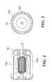
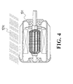
- the conventional cooling methods for enclosed type electrical machines usually adopt the free air cooling (as shown in fig. 1 and fig. 2), i.e. one or more than one dissipating fins 101a are installed at the outside casing of the enclosed type rotational electrical machine 10a to dissipate the accumulated heat of the rotational electrical machine through the free air convection for cooling; or adopt the external air forced cooling method(as shown Fig. 3), i.e. the enclosed type rotational electrical machine 10b is further installed with a fan 101b to blow the air for cooling; or adopt the liquid cooling method (as shown in Fig. 4), i.e. the rotational electrical machine 10c is cooled by the external coolant 101c.
- the free air cooling as shown in fig. 1 and fig. 2
- one or more than one dissipating fins 101a are installed at the outside casing of the enclosed type rotational electrical machine 10a to dissipate the accumulated heat of the rotational electrical machine through the free air convection for cooling
- the disadvantage of the aforesaid cooling technology is that the enclosed type rotational electrical machine's internal heat flow cannot be pumped out directly but have to relay on the enclosed type electrical machine's casing to dissipate the internally accumulated heat resulting a higher temperature difference between the inside and outside, therefore its heat dissipation is not very effective which affects the rotational electrical machine's performance very much.
- the invention discloses an innovative design of an enclosed type air cooler device of the rotational electrical machine, wherein it is characterized in the original creation of that the high temperature air flow inside the enclosed type rotational electrical machine is pumped out to the outside installed cooler device in enclosed type flow circuit and is then pumped back to the enclosed type rotational electrical machine inside without jeopardizing its closed tight functions.
- the enclosed type air cooler device of the enclosed type rotational electrical machine of the invention discloses an innovative design of an enclosed type air cooler device of a rotational electrical machine, wherein it is mainly constituted by a rotational electrical machine 1 and a cooler device 2, and it is mainly characterized in the following:
- FIG. 5 and 6 show one of the embodying examples of the invention, whereof it is comprised of that an air outlet 112a and an air inlet 111a are provided at the front and rear end of the casing 11a of the said rotational electrical machine 1a, and an integrally installed air cooler device 2a is further installed at the outside of the casing 11a, and the rotational electrical machine 1a is enclosed by the casing 21a of the said cooler 2a, whereby the casing 21a of the cooler device 2a and the casing 11a of the rotational electrical machine 1a form a tubular space 22a which is connected with the inlet 111a and the outlet 112a; further, a centrifugal type radial or axial fan 13a is installed on the power output shaft 12a located at the outlet 112a side of the rotational electrical machine 1; wherein the casing 21a of the cooler device 2a can be installed with several heat dissipating fins 212a which allow the cooler device 2a to match with a free air cooler device 3, or to match with with
- the centrifugal type radial or axial fan 13a is simultaneously driven to rotate by the said power output shaft 12a to pump the cooling gas contained heat from the outlet 112a to the tubular space 22a constituted by the cooler device 2a and through the internally installed heat dissipating fins 111a, 211a to transfer heat energy as well as further through the cooler device 2a to match with a free air cooler device 3 or to match with a conventional forced air cooler device 4, besides, the internal cooling circuits can be further installed inside the cooler device to match with the other final cooler devices such as a liquid cooler device 5 or a heat exchanger 6, etc.
- the tubular space 22a between the said rotational electrical machine 1a and the cooler device 2a is installed with heat absorbing fins 221a which causes the tubular space 22a to form a blended circuit shape, and through this to allow the said heat absorbing fins 221a to absorb the hot gas heat and transfer it to the outside thereby to improve the heat dissipating effect of the rotational electrical machine.
- the rotational electrical machine 1b and the cooler device 2b can be further made in the separated structures, whereof the inlet 111b and outlet 112b are provided at the casing 11b of the said rotational electrical machine 1b, whereof a centrifugal type radial or axial fan 13b is installed on the power output shaft 12b at the outlet 112b side (as shown in Fig.
- the said cooler device 2b forms a tubular circuit structure 22b which is not limited to a particular shape, besides of blended shape, it can be also formed to helical shape or other irregular shapes; whereof the said cooler device 2b can be matched with a free air cooler device 3 or the cooler device 2a can be matched with a forced air cooler device 4, and cooling circuits can be further installed inside the cooler device to match with a liquid cooler device 5 or to match with a heat exchanger 6, or the cooler device 2b can combine with several different cooling technologies to constitute in an integrated structure; through this, both ends of the tubular circuit structure 22b of the cooler device 2b are respectively connected to the inlet 111b and outlet 112b of the said rotational electrical machine 1b, wherein the rotational electrical machine 1b and the tubular circuit structure 22b of the cooler device 2b are filled in with air or other gases thereby to constitute the enclosed type air cooler device of the rotational electrical machine of the invention.
- the effect of the aforesaid embodying example is that when the rotational electrical machine 1b produces power, the centrifugal type radial or axial fan 13b is simultaneously driven by the power output shaft 12b to rotate whereby to pump the hot gas inside the rotational electrical machine 1b through the outlet 112b to the outside tubular circuit structure 22b constituted by the cooler device 2b, whereof the cooler device 2b is matched with a free air cooler device 3 or matched with a conventional forced air cooler device 4, or the cooling circuit can be installed inside the cooler device to match with a liquid cooler device 5 or to match with a heat exchanger device 6; wherein the cooled down coolant gas flow is pumped through the inlet 111b of the rotational electrical machine 1b to enter the rotational electrical machine 1b interior to provide cooling for the rotational electrical machine, thereby the accumulated heat inside the enclosed type electrical machine casing can be effectively removed thus to improve the cooling effect of the rotational electrical machine 1b.
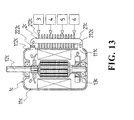
- the said cooler 2c is an independent structure and appear in a bended piping casing 21c, whereof one or more than one heat dissipating fins 212c are installed at the outside of the casing 21c; whereof the inlet 111c and outlet 112c are respectively provided at selected locations on the casing 11c of the said rotational electrical machine 1c, further, its internal power output shaft 12c is also installed with a centrifugal type radial or axial fan 13c (as shown in Fig.
- the inlet of the cooler device 2c is connected to the outlet 112c of the rotational electrical machine 1c, and the said cooler device 2c is further connected to the inlet 111c of the rotational electrical machine 1c to allow the said cooler device 2c to be attached or ring installed at the outside of the casing 11c whereby to cause the cooler device 2c and the casing of the rotational electrical machine 1c appear a special and inter-combined structure; thereby the hot gas is pumped to the cooler device 2c through the centrifugal type radial or axial fan 13c to achieve the aforesaid circulating heat dissipation effect.
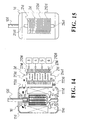
- the further embodying example structure of the invention is as shown in Fig. 14 and 15, whereof the cooler device 2d is comprised of a casing 21d with an internally installed air chamber 22d, whereof the outside of the casing 21d is installed with several heat dissipating fins 212d and the inside of the air chamber 22d is installed with heat absorbing fins 221d whereby to cause the said air chamber 22d constitute a bended circuit shape, and the both ends of the casing 21d are respectively provided with inlet 213d and outlet 214d; besides, the inlet 111d and the outlet 112d are respectively provided at proper locations on the casing 11d of the said rotational electrical machine 1d, whereof its internal power output shaft 12d is installed with a centrifugal type radial or axial fan 13d (as shown in Fig.
- the inlet pipe 213d of the said cooler device 2d is connected to the outlet 112d of the rotational electrical machine 1d, while the outlet pipe 214d of the said cooler device 2d is further connected to the inlet 111d of the rotational electrical machine 1d thereby to allow the said cooler device 2d be attached to the outside of the casing lid, wherein the cooler device 2d and the casing of the rotational electrical machine 1d are individually independent structures and they are further combined; thereby the hot gas is pumped to the cooler device 2d through the centrifugal type radial or axial fan 13d installed inside the said rotational electrical machine 1d to achieve the aforesaid circulating heat dissipating effect.
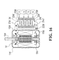
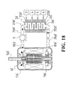
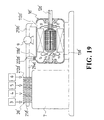
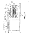
- the cooler device 2d' and the rotational electrical machine 1d' of the invention can also be separated (as shown in Fig. 17 or Fig. 18) and interconnected through the inlet pipe 213d' and the outlet pipe 214d' whereby to constitute an enclosed type air cooling circuit structure of the invention, wherein the said cooler device 2d' can be installed at other proper locations as required (as shown in Fig. 19 or Fig. 20), i.e.
- the cooler device 2d' can be installed on the casing 7 of other machine and is further matched with a free air cooler device 3, or the cooler device 2a can be matched with a conventional forced air cooler device 4, in addition, the cooling circuits can be installed inside the cooler device to match with a liquid cooler device 5 or to match with a heat exchanger 6 whereby the hot gas inside the cooler device 2d' can be cooled and pumped to the rotational electrical machine 1d' interior to effectively remove the accumulated heat inside the enclosed type rotational electrical machine casing thereby to improve the cooling effect.
- the cooler device of the invention can be directly designed to have an integrated structure with other devices (as shown in Fig. 21 or Fig. 22), whereof the cooler device 2e is in an integrated structure with the casing 81 of the transmission mechanism 8 and the outside of the casing 81 is made into a air chamber 22e, wherein several heat absorbing fins 221e are installed at the inside of the said air chamber 22e, and through the arrangement of the heat absorbing fins 221e to make the air chamber 22e constitute a bended circuit shape to improve its heat absorbing effect; thereof through the combination of the said rotational electrical machine 1e and the casing 81 of the transmission mechanism 8, its outlet 112e can be connected to the inlet of the cooler device 2e, and the circuit end of the air chamber 22e is connected with an outlet pipe 214e which is further connected to the inlet 111e of the rotational electrical machine 1e thereby to constitute the enclosed type cooling flow circuit structure of the invention whereby to achieve the aim of improving the heat dissipating effect
- the pumping methods for the cooling air or other gases in the invention include the following:
- the internal air chamber of the cooler device 2 in the aforesaid embodying examples can be an empty space or installed with internal heat conducting fins or can be further installed with air filter devices 222a, 222b, 222c, 222d, 222e or simultaneously installed with an clean cover or clean plug for opening/closing to remove the condensed moisture or the internally eroded fragment powders generated inside the rotational electrical machines 1a, 1b 1c, 1d, 1e, such as the brush fragment powders of the DC machines thereby to avoid affecting the operating functions.
- the said cooler device 2f of the invention can also be used to provide a heating source function, wherein the pipe 22f can be coupled with the heating target 100, and the hot gas produced by the rotational electrical machine 1 is passed through the pipe 22f to heat up the heating target coupled with the pipe 22f such as the car batteries.
- a distributing pipe 22f' and a control valve 200 (as shown in Fig.
- the said control valve 200 can be operated manually or controlled through detection of the conventional temperature sensor device T100 which is selectively installed according to the requirements on the heating target to do bypass or distributing flow when reaching the set temperature in order to reduce or stop the heating process on the target objects; or the outside of the said pipe 22f as shown in Fig.
- a air guiding pipe 223f to provide heat exchanged output from the hot gas flow produced by the rotational electrical machine so as to provide heating gas for other places' use, such as to produce warming effect in an enclosed or semi-enclosed space or warming up the car battery, etc.
- the invention has disclosed an innovative design of an enclosed type air cooler device of the rotational electrical machine, wherein it is characterized in that the hot gas inside the enclosed type rotational electrical machine is pumped out to the outside air cooler device in an enclosed type air flow circuit and is then pumped back to the inside of the enclosed type rotational electrical machine without jeopardizing its enclosed function, therein it effectively improves the cooling effect of the enclosed type rotational electrical machine.
Landscapes
- Engineering & Computer Science (AREA)
- Power Engineering (AREA)
- Motor Or Generator Cooling System (AREA)
- Motor Or Generator Frames (AREA)
Applications Claiming Priority (5)
| Application Number | Priority Date | Filing Date | Title |
|---|---|---|---|
| CN00109035A CN1327294A (zh) | 2000-06-05 | 2000-06-05 | 具有封闭型冷却结构的回转电机 |
| CN00109035 | 2000-06-05 | ||
| CN002364794U CN2427922Y (zh) | 2000-06-05 | 2000-06-05 | 具有封闭型冷却结构的回转电机 |
| US09/628,427 US6700237B1 (en) | 2000-06-05 | 2000-07-28 | Enclosed air cooler device for a rotational electrical machine |
| JP2000241165A JP2002058205A (ja) | 2000-06-05 | 2000-08-09 | 回転電動機 |
Publications (2)
| Publication Number | Publication Date |
|---|---|
| EP1162718A2 true EP1162718A2 (de) | 2001-12-12 |
| EP1162718A3 EP1162718A3 (de) | 2004-05-12 |
Family
ID=53871762
Family Applications (1)
| Application Number | Title | Priority Date | Filing Date |
|---|---|---|---|
| EP01304739A Withdrawn EP1162718A3 (de) | 2000-06-05 | 2001-05-30 | Luftkühlungsanordnung für elektrische Maschinen |
Country Status (4)
| Country | Link |
|---|---|
| US (1) | US6700237B1 (de) |
| EP (1) | EP1162718A3 (de) |
| JP (1) | JP2002058205A (de) |
| CN (2) | CN1327294A (de) |
Cited By (7)
| Publication number | Priority date | Publication date | Assignee | Title |
|---|---|---|---|---|
| WO2011082825A1 (en) * | 2010-01-07 | 2011-07-14 | Avure Technologies Ab | High-pressure press |
| EP2086091A3 (de) * | 2008-02-04 | 2011-12-21 | Traktionssysteme Austria GmbH | Luftgekühlte elektrische Maschine |
| CN109194032A (zh) * | 2018-10-22 | 2019-01-11 | 王秋林 | 一种散热效果好的直流电机 |
| CN110829689A (zh) * | 2019-11-19 | 2020-02-21 | 兰州理工大学 | 液流-气流-翅片联合散热的液压电机泵壳体 |
| CN116014977A (zh) * | 2022-10-10 | 2023-04-25 | 江苏明磁动力科技有限公司 | 一种用于高速电机的均匀式冷却结构 |
| CN116979755A (zh) * | 2023-06-29 | 2023-10-31 | 上海大速科技有限公司 | 一种具有高效散热功能的防爆型三相异步电动机 |
| CN118137746A (zh) * | 2024-05-10 | 2024-06-04 | 江苏赛夫特防爆电气有限公司 | 一种风力发电机用冷却器 |
Families Citing this family (42)
| Publication number | Priority date | Publication date | Assignee | Title |
|---|---|---|---|---|
| US7109613B2 (en) * | 2004-04-21 | 2006-09-19 | Choon Nang Electrical Appliance Mfy., Ltd. | Power hand tool |
| JP3831736B2 (ja) | 2004-07-30 | 2006-10-11 | 三菱重工業株式会社 | 空気冷媒式冷却装置と空気冷媒式冷却装置を用いた空気冷媒冷熱システム |
| JP2006050683A (ja) * | 2004-07-30 | 2006-02-16 | Toshiba Corp | 車両用全閉形電動機 |
| ITMI20060294A1 (it) * | 2006-02-17 | 2007-08-18 | Nuovo Pignone Spa | Motocompressore |
| DE102007021723B4 (de) * | 2007-05-09 | 2009-09-17 | Siemens Ag | Luftgekühlte rotierende elektrische Maschine |
| US7990005B2 (en) * | 2008-02-07 | 2011-08-02 | Atlas Dynamic Devices, Llc | Power transmission tool and system |
| US8402784B2 (en) * | 2008-03-13 | 2013-03-26 | Machflow Energy, Inc. | Cylindrical Bernoulli heat pumps |
| EP2182611B1 (de) * | 2008-10-28 | 2013-03-06 | Siemens Aktiengesellschaft | Anordnung zur Kühlung einer elektrischen Maschine |
| EA200900548A1 (ru) * | 2009-03-31 | 2009-12-30 | Открытое Акционерное Общество "Инжиниринговая Нефтегазовая Компания - Всероссийский Научно-Исследовательский Институт По Строительству И Эксплуатации Трубопроводов, Объектов Тэк" | Система охлаждения статора вентильной машины обращенного типа |
| CN102577045A (zh) * | 2009-10-01 | 2012-07-11 | Abb公司 | 用于电动机器的冷却系统 |
| DE102009051651B4 (de) * | 2009-11-02 | 2012-01-26 | Siemens Aktiengesellschaft | Windkraftgenerator mit Innenkühlkreislauf |
| US20120045352A1 (en) * | 2010-08-23 | 2012-02-23 | Justin Lawyer | Pump and pump assembly |
| US20120318479A1 (en) * | 2011-06-14 | 2012-12-20 | Fukuta Electric & Machinery Co., Ltd. | Liquid cooled motor assembly and cover thereof |
| CN103987636B (zh) | 2011-08-11 | 2016-04-06 | 摩尔转动带系统有限公司 | 安装面系统 |
| US8912698B2 (en) | 2011-10-03 | 2014-12-16 | Elco Motor Yachts, LLC | Motor assembly with integrated cooling means and enclosed compartment for electronic circuitry |
| JP2013118742A (ja) * | 2011-12-02 | 2013-06-13 | Hitachi Industrial Equipment Systems Co Ltd | 密閉型電動機及び密閉型電動機の冷却装置 |
| DE102012200363A1 (de) * | 2012-01-11 | 2013-07-11 | Metabowerke Gmbh | Elektrischer Antrieb sowie Dichtgehäuse hierfür |
| KR101354670B1 (ko) * | 2012-08-31 | 2014-02-03 | 한국과학기술원 | 발전기 |
| CN104009583A (zh) * | 2013-02-26 | 2014-08-27 | 上海仕强电气有限公司 | 一种内风冷电动机 |
| CN103219831A (zh) * | 2013-03-22 | 2013-07-24 | 天津市松正电动汽车技术股份有限公司 | 气冷电机及新能源汽车电池加热装置 |
| CN103236761A (zh) * | 2013-05-22 | 2013-08-07 | 湘潭电机股份有限公司 | 一种带自冷风扇的电机 |
| USD716227S1 (en) * | 2013-09-12 | 2014-10-28 | Johnson Electric S.A. | Electric motor |
| USD716226S1 (en) * | 2013-09-12 | 2014-10-28 | Johnson Electric S.A. | Electric motor |
| USD722560S1 (en) * | 2013-09-12 | 2015-02-17 | Johnson Electric S.A. | Electric motor |
| JP6378536B2 (ja) * | 2014-05-21 | 2018-08-22 | Tone株式会社 | 空冷機構を具える電動工具 |
| KR101765583B1 (ko) * | 2014-07-29 | 2017-08-07 | 현대자동차 주식회사 | 공기 압축기의 냉각유닛 |
| DE102014216148A1 (de) | 2014-08-14 | 2016-02-18 | Wobben Properties Gmbh | Synchrongenerator, insbesondere vielpoliger Synchron-Ringgenerator einer getriebelosen Windenergieanlage, und Windenergieanlage mit selbigem |
| CN105896224A (zh) * | 2015-01-22 | 2016-08-24 | 贵州航空发动机研究所 | 一种引电器的高速刷环冷却装置 |
| KR101888156B1 (ko) * | 2016-11-14 | 2018-08-13 | ㈜티앤이코리아 | 분리된 냉각 기로를 구비한 터보 압축기 |
| CN106451917B (zh) * | 2016-11-30 | 2023-04-21 | 北京三一智能电机有限公司 | 发电机和风力发电设备 |
| CN106968891A (zh) * | 2017-03-02 | 2017-07-21 | 安徽蜂鸟电机有限公司 | 一种新型风力发电机 |
| CN107147230B (zh) * | 2017-06-13 | 2022-11-29 | 定兴县宇捷直流力矩电机制造有限公司 | 一种配置霍尔元件的无公约数奇数槽分数槽分布绕组 |
| CN108512340A (zh) * | 2018-01-24 | 2018-09-07 | 汇源印刷包装科技(天津)股份有限公司 | 一种印刷机物流系统用电机 |
| JP7210975B2 (ja) * | 2018-09-28 | 2023-01-24 | 日本電産トーソク株式会社 | モータユニット |
| JP7038074B2 (ja) * | 2019-03-22 | 2022-03-17 | 東芝三菱電機産業システム株式会社 | 回転電機およびロータシャフト |
| CN110518751B (zh) * | 2019-09-02 | 2021-12-24 | 武汉鑫联兴精密机电有限公司 | 一种内部带有感温智能调节温度机构的电机 |
| US12155290B2 (en) * | 2019-12-09 | 2024-11-26 | Weg Equipamentos Elétricos S.a. | Electronically commutated rotating electrical machine with a gap in a housing for cooling air flow |
| US11973398B2 (en) | 2020-03-31 | 2024-04-30 | Dana Belgium N.V. | Electric motor cooling system and method for operation of said system |
| WO2022109787A1 (zh) * | 2020-11-24 | 2022-06-02 | 江苏金彭集团有限公司 | 一种电动车用封闭式防水直流电动机 |
| CN112726449B (zh) * | 2020-12-17 | 2022-09-30 | 聊城市瀚格智能科技有限公司 | 一种具有自清洁功能的山路弯道球面镜 |
| CN114583879B (zh) * | 2022-03-05 | 2023-05-23 | 江西昌龙电机有限公司 | 一种散热效果好的微型电机 |
| CN114593198B (zh) * | 2022-04-25 | 2022-08-02 | 沃德传动(天津)股份有限公司 | 一种减速机及其辅助润滑结构 |
Family Cites Families (28)
| Publication number | Priority date | Publication date | Assignee | Title |
|---|---|---|---|---|
| US3610975A (en) * | 1969-07-30 | 1971-10-05 | Westinghouse Electric Corp | Dynamoelectric machine with improved cooling means |
| US3725705A (en) * | 1972-02-02 | 1973-04-03 | A Borinski | Method for storing electric energy and an electric energy storing system |
| US3749953A (en) * | 1972-02-24 | 1973-07-31 | Gen Electric | Ventilated dynamoelectric machines |
| FR2259343A1 (en) * | 1974-01-29 | 1975-08-22 | Unelec | Heat exchanger for electric motor - air supply travels on meander path between hollow tubular heat exchanger walls |
| FR2407597A1 (fr) * | 1977-10-26 | 1979-05-25 | Cem Comp Electro Mec | Perfectionnements aux moteurs electriques fermes a refroidissement par eau |
| US4244098A (en) * | 1978-05-26 | 1981-01-13 | General Electric Company | Method of assembling a dynamoelectric machine and an auxiliary cooling device |
| DE2908717C2 (de) * | 1979-03-06 | 1983-12-22 | Siemens AG, 1000 Berlin und 8000 München | Wärmetauscher |
| DE3032591A1 (de) * | 1980-08-27 | 1982-04-01 | Siemens AG, 1000 Berlin und 8000 München | Anordnung zur kuehlung einer gas- oder fluessigkeitsgekuehlten elektrischen maschine |
| DE3032590A1 (de) * | 1980-08-27 | 1982-04-01 | Siemens AG, 1000 Berlin und 8000 München | Anordnung zur kuehlung einer gas- oder fluessigkeitsgekuehlten elektrischen maschine |
| JPS5768640A (en) * | 1980-10-15 | 1982-04-27 | Fanuc Ltd | Cooler for both directionally rotating motor |
| JPS5917842A (ja) * | 1982-07-20 | 1984-01-30 | Fuji Electric Co Ltd | 全閉形ヒ−トパイプ付回転電機 |
| US4814653A (en) * | 1986-12-30 | 1989-03-21 | Hitachi, Ltd. | Device for air cooling bearing of hermetic dynamic machine |
| US4742257A (en) * | 1987-01-29 | 1988-05-03 | General Motors Corporation | Totally enclosed fan cooled induction motor with improved cooling |
| US4839547A (en) * | 1988-03-28 | 1989-06-13 | Wertec Corporation | Motor frame and motor with increased cooling capacity |
| US4908538A (en) * | 1989-02-28 | 1990-03-13 | Geberth John Daniel Jun | Totally enclosed electric motor |
| DE4138268A1 (de) * | 1991-11-21 | 1993-05-27 | Klein Schanzlin & Becker Ag | Elektromotor |
| JPH06153448A (ja) * | 1992-10-28 | 1994-05-31 | Mitsubishi Electric Corp | 全閉外扇形回転電機 |
| JP3475973B2 (ja) * | 1994-12-14 | 2003-12-10 | 株式会社ニコン | リニアモータ、ステージ装置、及び露光装置 |
| DE19510018C2 (de) * | 1995-03-20 | 1997-02-06 | Loher Ag | Elektromotor oder Generator mit Kühlrohren |
| US5770903A (en) * | 1995-06-20 | 1998-06-23 | Sundstrand Corporation | Reflux-cooled electro-mechanical device |
| JPH09149599A (ja) * | 1995-11-27 | 1997-06-06 | Hitachi Ltd | 全閉形回転電機 |
| JPH09154254A (ja) * | 1995-11-28 | 1997-06-10 | Toshiba Corp | 車両用全閉形主電動機 |
| JPH09163683A (ja) * | 1995-12-06 | 1997-06-20 | Toshiba Corp | 回転電機 |
| JP3332729B2 (ja) * | 1996-06-21 | 2002-10-07 | 株式会社東芝 | 車両用全閉形主電動機 |
| JP2966799B2 (ja) * | 1996-11-07 | 1999-10-25 | ファナック株式会社 | 空冷式モータ |
| US5844333A (en) * | 1996-11-12 | 1998-12-01 | Unifin International, Inc. | Device and method for cooling a motor |
| JPH11356011A (ja) * | 1998-06-09 | 1999-12-24 | Toshiba Transport Eng Inc | 車両用全閉形主電動機 |
| JP3559891B2 (ja) * | 1998-06-22 | 2004-09-02 | 日産自動車株式会社 | 多層モータの冷却構造 |
-
2000
- 2000-06-05 CN CN00109035A patent/CN1327294A/zh active Pending
- 2000-06-05 CN CN002364794U patent/CN2427922Y/zh not_active Expired - Fee Related
- 2000-07-28 US US09/628,427 patent/US6700237B1/en not_active Expired - Fee Related
- 2000-08-09 JP JP2000241165A patent/JP2002058205A/ja active Pending
-
2001
- 2001-05-30 EP EP01304739A patent/EP1162718A3/de not_active Withdrawn
Cited By (10)
| Publication number | Priority date | Publication date | Assignee | Title |
|---|---|---|---|---|
| EP2086091A3 (de) * | 2008-02-04 | 2011-12-21 | Traktionssysteme Austria GmbH | Luftgekühlte elektrische Maschine |
| WO2011082825A1 (en) * | 2010-01-07 | 2011-07-14 | Avure Technologies Ab | High-pressure press |
| US8764432B2 (en) | 2010-01-07 | 2014-07-01 | Avure Technologies Ab | High-pressure press |
| CN102781656B (zh) * | 2010-01-07 | 2015-05-13 | 艾维尔技术公司 | 高压压机 |
| CN109194032A (zh) * | 2018-10-22 | 2019-01-11 | 王秋林 | 一种散热效果好的直流电机 |
| CN110829689A (zh) * | 2019-11-19 | 2020-02-21 | 兰州理工大学 | 液流-气流-翅片联合散热的液压电机泵壳体 |
| CN116014977A (zh) * | 2022-10-10 | 2023-04-25 | 江苏明磁动力科技有限公司 | 一种用于高速电机的均匀式冷却结构 |
| CN116979755A (zh) * | 2023-06-29 | 2023-10-31 | 上海大速科技有限公司 | 一种具有高效散热功能的防爆型三相异步电动机 |
| CN116979755B (zh) * | 2023-06-29 | 2024-03-26 | 上海大速科技有限公司 | 一种具有高效散热功能的防爆型三相异步电动机 |
| CN118137746A (zh) * | 2024-05-10 | 2024-06-04 | 江苏赛夫特防爆电气有限公司 | 一种风力发电机用冷却器 |
Also Published As
| Publication number | Publication date |
|---|---|
| CN1327294A (zh) | 2001-12-19 |
| CN2427922Y (zh) | 2001-04-25 |
| EP1162718A3 (de) | 2004-05-12 |
| JP2002058205A (ja) | 2002-02-22 |
| US6700237B1 (en) | 2004-03-02 |
Similar Documents
| Publication | Publication Date | Title |
|---|---|---|
| EP1162718A2 (de) | Luftkühlungsanordnung für elektrische Maschinen | |
| US6186755B1 (en) | Scroll fluid machine having a heat pipe inside the drive shaft | |
| CN100513932C (zh) | 热电联合系统 | |
| CN103415984B (zh) | 用于在电机中增加气流的系统和方法 | |
| US20120086217A1 (en) | Power Generation Apparatus | |
| CN110173402A (zh) | 风力涡轮机冷却布置结构 | |
| EP3413129B1 (de) | Wärmeableitvorrichtung für ein farbrad und projektionsvorrichtung mit der wärmeableitvorrichtung | |
| US5338162A (en) | High-pressure cleaner with air-cooled motor | |
| KR100892530B1 (ko) | 스크류 냉각식 진공 펌프 | |
| CN217307076U (zh) | 一种充气式环网设备 | |
| CN111365236B (zh) | 干式螺杆压缩机 | |
| JP2019092371A (ja) | 交換機および複数の冷却回路を含む電動モータ | |
| US4313493A (en) | Forced air unit | |
| CN217010616U (zh) | 一种具有水冷散热结构的多功能高转速马达 | |
| CN115133712B (zh) | 一种具有自散热功能的电机 | |
| JP3075563U (ja) | 回転電動機 | |
| JP2004299446A (ja) | 車両用熱交換器 | |
| CN212696430U (zh) | 散热装置、电子设备及集成灶 | |
| CN113765284A (zh) | 一种外接隔爆型电机散热器 | |
| KR100316609B1 (ko) | 펌프용 모터의 냉각장치 | |
| JPH06237554A (ja) | バルブ水車発電機 | |
| CN223553168U (zh) | 一种用于驱动电机的冷却装置 | |
| CN220489775U (zh) | 一种硅烷交联聚乙烯电缆料用冷却塔 | |
| US20080317612A1 (en) | Auxiliary engine driven device and methods for use thereof | |
| CN219374431U (zh) | 一种通风散热结构及带有通风散热结构的集成灶 |
Legal Events
| Date | Code | Title | Description |
|---|---|---|---|
| PUAI | Public reference made under article 153(3) epc to a published international application that has entered the european phase |
Free format text: ORIGINAL CODE: 0009012 |
|
| AK | Designated contracting states |
Kind code of ref document: A2 Designated state(s): AT BE CH CY DE DK ES FI FR GB GR IE IT LI LU MC NL PT SE TR |
|
| AX | Request for extension of the european patent |
Free format text: AL;LT;LV;MK;RO;SI |
|
| PUAL | Search report despatched |
Free format text: ORIGINAL CODE: 0009013 |
|
| AK | Designated contracting states |
Kind code of ref document: A3 Designated state(s): AT BE CH CY DE DK ES FI FR GB GR IE IT LI LU MC NL PT SE TR |
|
| AX | Request for extension of the european patent |
Extension state: AL LT LV MK RO SI |
|
| AKX | Designation fees paid | ||
| REG | Reference to a national code |
Ref country code: DE Ref legal event code: 8566 |
|
| STAA | Information on the status of an ep patent application or granted ep patent |
Free format text: STATUS: THE APPLICATION IS DEEMED TO BE WITHDRAWN |
|
| 18D | Application deemed to be withdrawn |
Effective date: 20041201 |